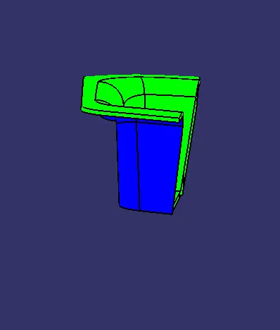
Week 9 - Challenge 2 - Switch Bezel Design
Switch Bezel
Objectives
- Create a plastic component of certain thickness (2.5mm) using the given Class A surface
- Create a proper tooling axis for the component
- Perform Draft analysis for both the Class A and the final component
Tooling Axis
Tooling axis is the direction in which the mould and the cavity opens. There are two methods in creating the tooling axis
- Bisecting method
- Point-direction method
For this component bisecting method is used to create the tooling axis
Bisecting method of creating tooling axis
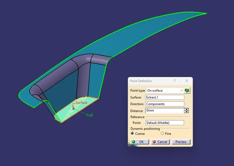
- First a reference point is created on the Class A surface and then the direction is considered
- For this component Z-axis ensures the proper direction to eject component hence the tooling axis is created along the Z-Axis
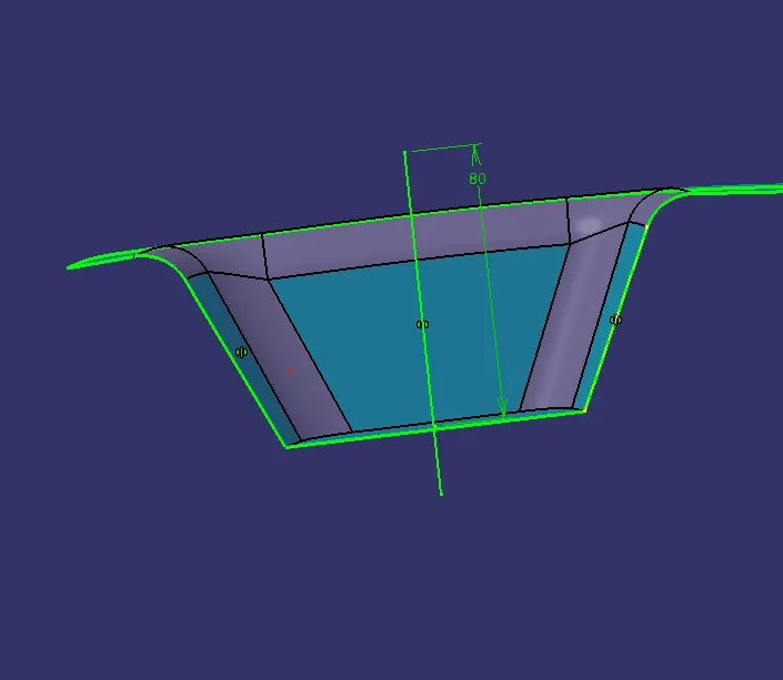
- The x- and y-axes along with class A were used to develop a bisecting line using the Intersection curve
- Considering to similar sides a line is created which passes through the centre point and in Z axis-direction
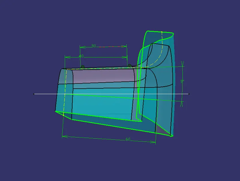
- Another line at an angle form another surface, which is perpendicular to those two similar surfaces is created, which passes through the same point
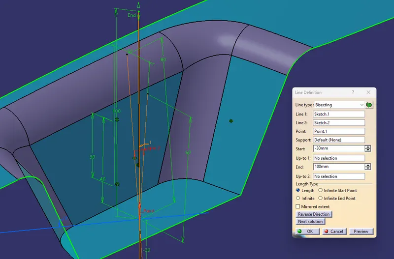
- Then the tooling axis is created by bisecting the above mentioned two lines
- To differentiate the appearance of the tooling axis its display properties are customized and then published
Draft analysis
A draft of minimum 3 degree must be provided on both core and cavity sides in a component for smooth ejection and for good surface quality. As the plastic shrinks and sticks onto the molding surfaces as it cools, walls of the plastic part should have a minimum draft so that it ejects or breaks free from the molding surfaces easily and without any drag.
Advantages of draft in injection molding
- Reduces the possibilities of part damage caused by friction during ejection process
- Reduces wear and tear in mold
- Helps to obtain uniform,smooth and unscratched surface
- Decreases overall cooling time by eliminating the need for unusual ejection setups
Nominal Values of Draft angles
- 3 Degree is a nominal draft angle
- 5 degree is possible but increases the manufacturing cost
- 7 degree considered for textured surfaces of parts
Performing Draft analysis
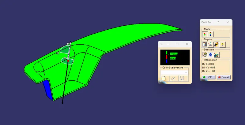
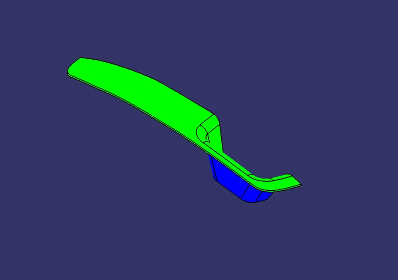
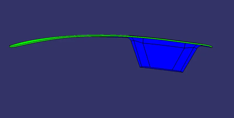
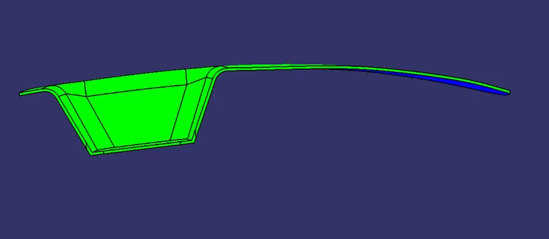
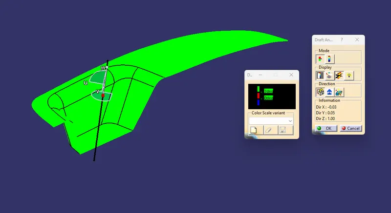
- Draft analysis is performed for both the given Class A surface and the component created out of it
- First the component is view mode is changed to material mode
- Selecting the “Feature Draft Analysis” command in the “Analysis” toolbar enables various parameters for performing draft analysis
- The compass is enabled and placed in the tooling axis and its direction is inverted along the tooling direction of the component
- The component is selected for draft analysis, the color code is customized according to the requirements using the Color Scale option.
- To view the angle at various points “analyses under the running point command is used”
Creating the component
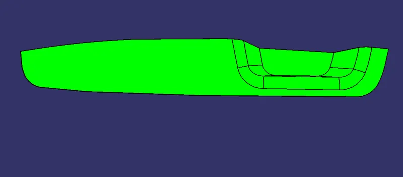
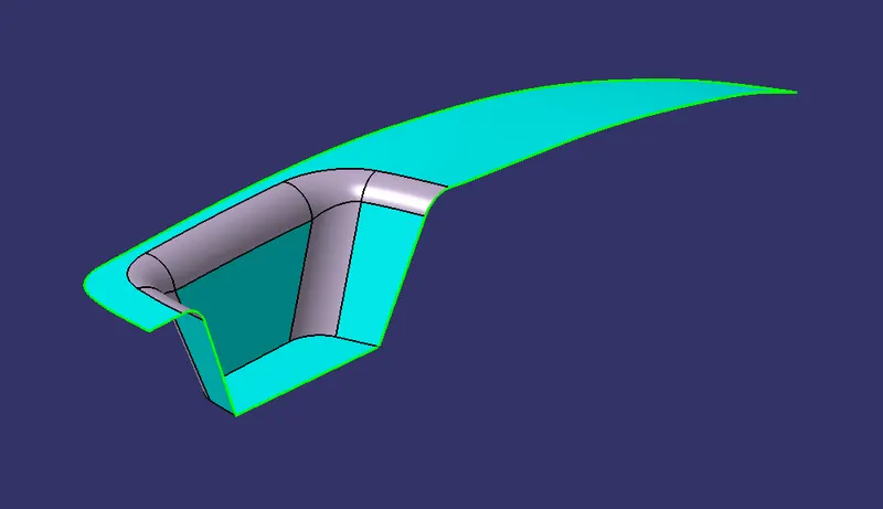
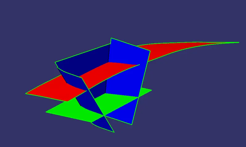
Input Class A is given
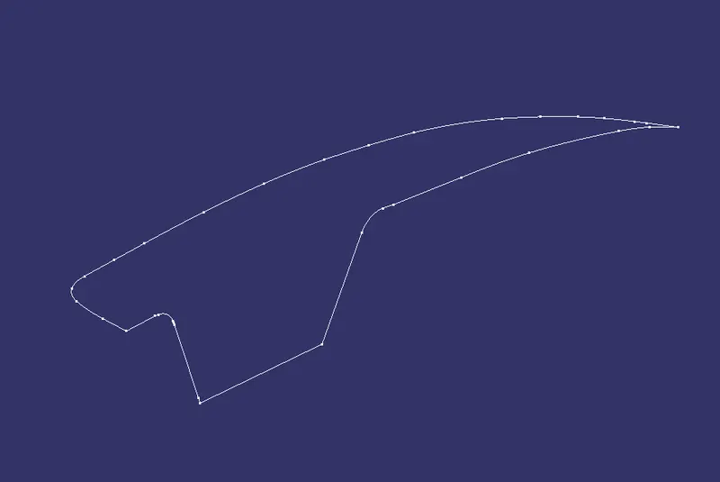
- As the first step the draft analysis is performed and the surface is checked for any open boundaries
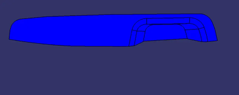
Class B
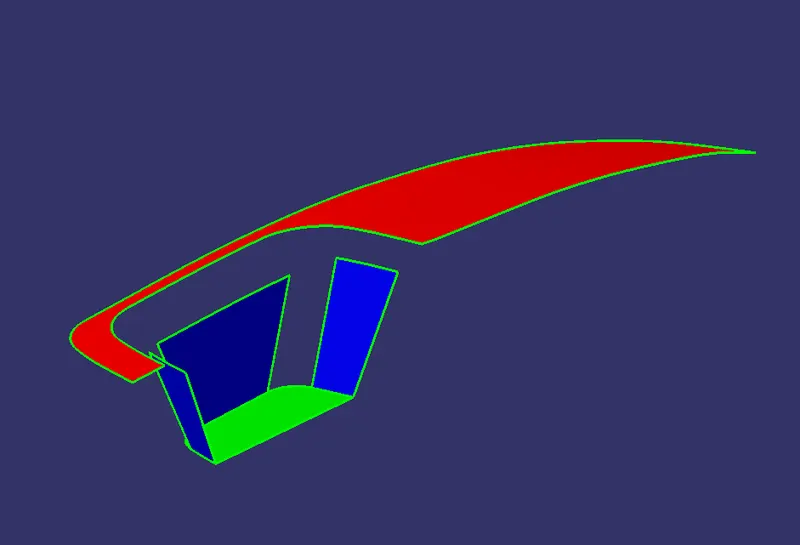
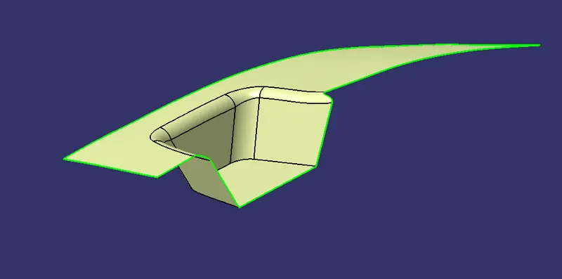
- All individual surfaces are extracted, untrimmed, and offset to a certain distance (2.5mm)
- The excess portions are trimmed and joined using Trim tool
- Then the fillets are applied respectively
Class C
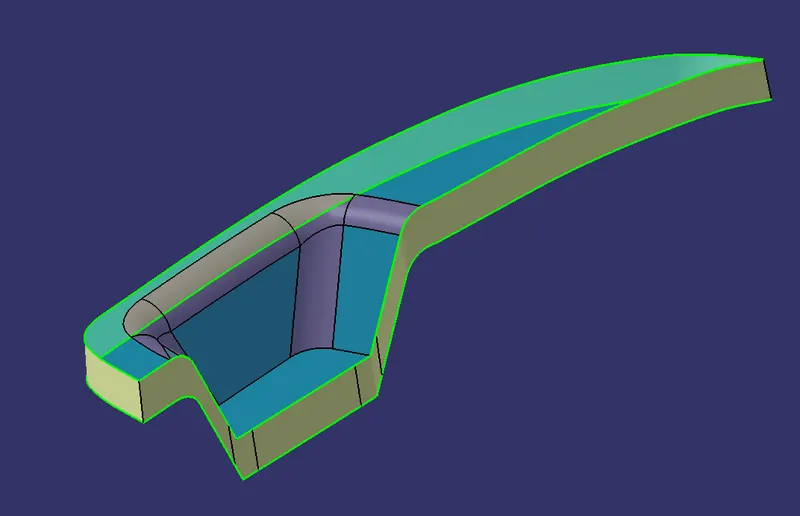
- The Boundaries of the Class A surface are extracted
- Using the boundaries, surfaces are swept along a certain degree with respect to the tooling axis
- Using trim tool the edges are trimmed and the surfaces are joined together
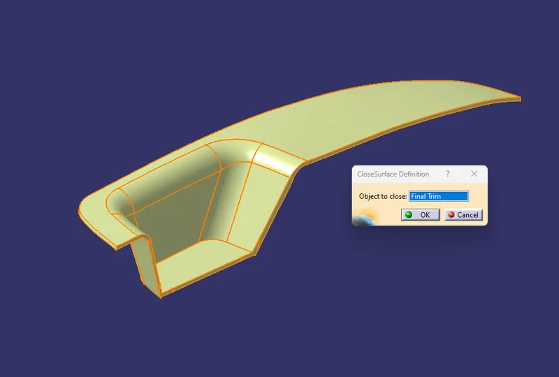
Final trim
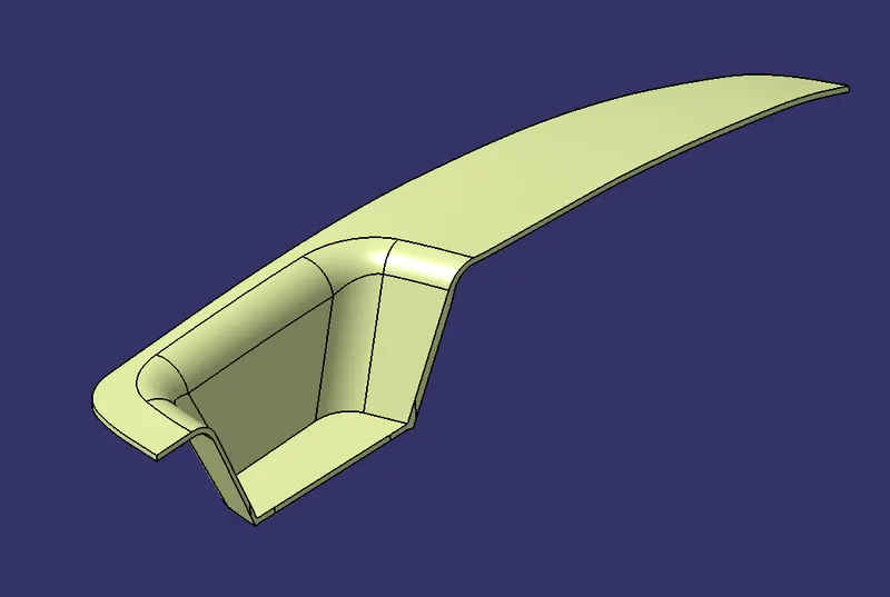
- Using Join command the class A and the Class C surfaces are joined together
- Then the Class B surface is trimmed and merged with the joined surface using trim tool
Creating Solid Component
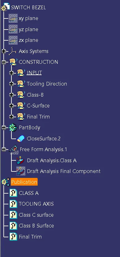
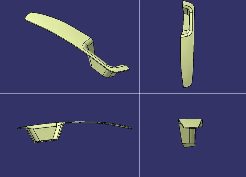
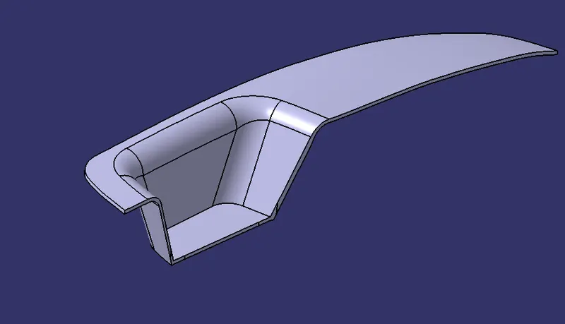
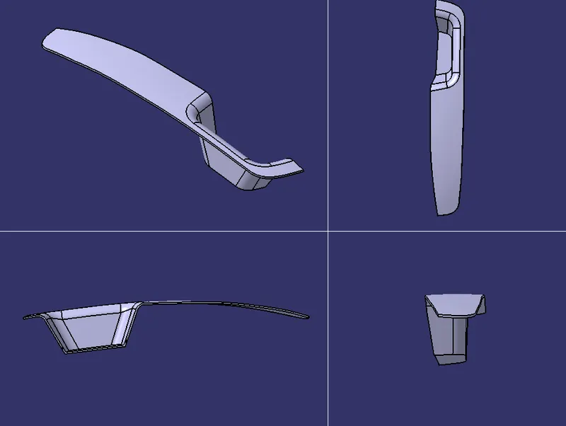
- With the help of Closed Surface command in the part workbench a solid component is created
Performing Draft analysis on final component