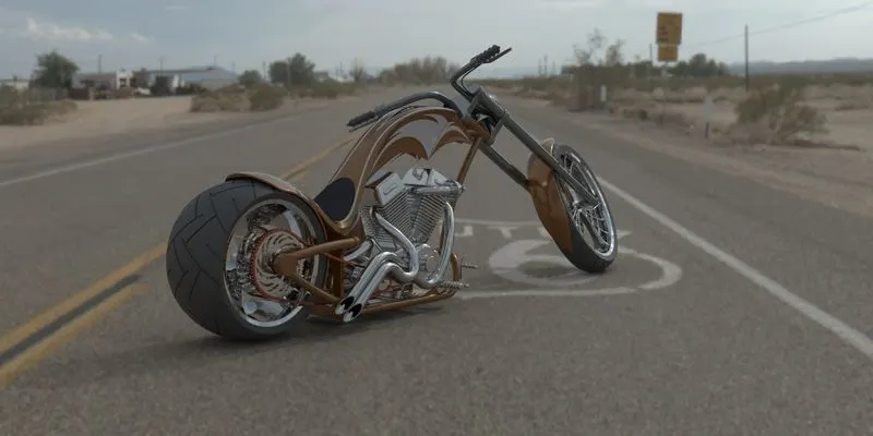
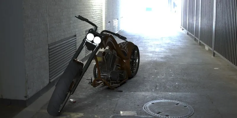
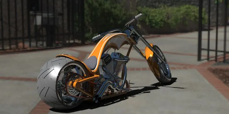
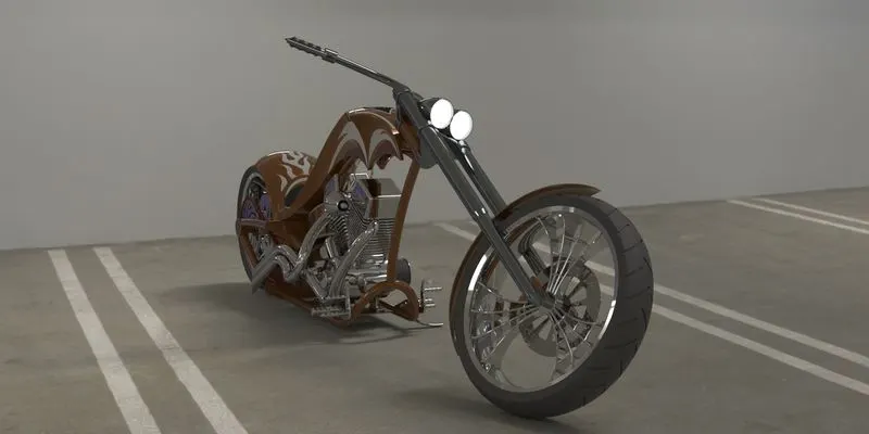
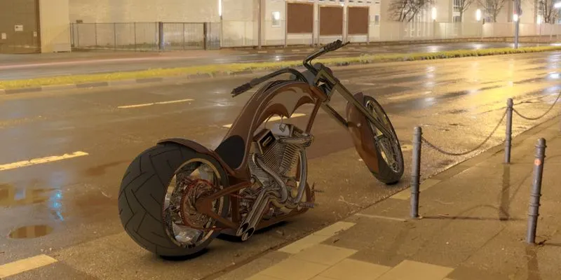
Photo Realistic Rendering
MODELING OF AMERICAN CHOPPER ON
SOLID WORKS
INTRODUCTION
In this project we are to learn how to model an American chopper on Solidworks and Solidworks visualize.
The various components of the American chopper we deal are;
1.Chassis of the chopper
2.Engine with the exhaust systems
3.Front and Rear wheels with Rims, Sprocket and brake Calipers
- Front fork along with Handle bars and grips
- Front and Rear fenders
- Oil tank
- Chain and Transmission belt
8.Kick Stand and the foot pedal
After completion of the design of the part components of the chopper, we have worked on the assembling of all the components and the photo render of the chopper which gives the complete and realistic view.
DESIGN APPROACH
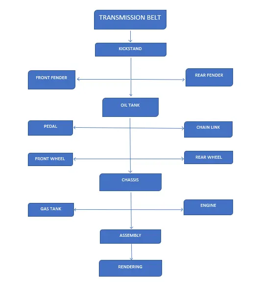
Starting with the design of transmission belt and till the photorealistic rendering section has been described step by step by means of flow chart.
Let’s discuss the various features and properties used in the entire model to design different parts.
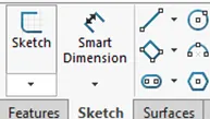
SKETCH: The sketch forms the basic structure or blueprint for the 3d component. It may be either 2D or 3D sketches. In 2D we select the plane on which we are up to sketch and select the 2D sketch option in the sketch tab in the Command manager. Once the sketch is completed it may be converted into 3D components or surfaces and etc. In 2D we’ll be able to sketch along two axes respect to the plane or surface we are sketching on. On the other hand, 3D sketching enables us to sketch over 3 axes independent of particular plane or surface. it does not require any surfaces or planes to be defined to sketch on.
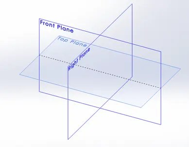
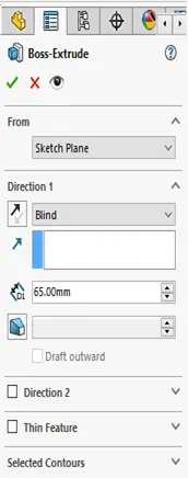
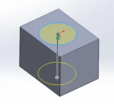
EXTRUDE: The EXTRUDE is the most basic of all features in Solidworks, that is mostly used in Solidworks to convert a completely closed sketch into a 3D solid component or add material along a straight path. It is classified under sketched feature as it requires a closed sketch to enable this feature. Once a closed sketch has been created exit the sketch and go to Features tab in the Command Manager and select the Extrude Boss/Base command, select the sketch to be extruded. The property manager in the extrude option allows us to make several changes such as dept depth direction of extrude, starting and ending location for extrude and many other parameters.
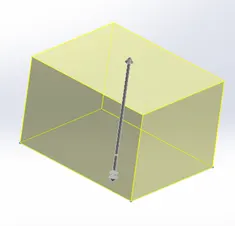
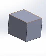
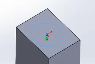
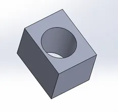
Extrude Cut: This feature is similar to the Extrude Boss/Base, this requires a closed sketch to remove the materials respect to the dimensions of sketch. It also allows us to modify various parameters in the property manager.
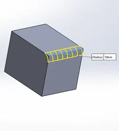
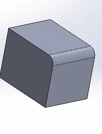
FILLETS: The fillets are used to make a sharp edge of a 3D component to a rounded smooth edge. Unlike Extrude feature it does not require any sketched entities to use Fillet feature and thus it is classified under applied features. The fillet creates a rounded edge by the means of either adding or removing the material, depending on whether the edge in internal or external. It makes the rounded edge tangent to the surfaces of which the fillet is made. We cannot create fillets of different size at single fillet. It is best practice to create larger fillets first and follow the smaller ones.
REVOLVED BOSS: This feature is used to create a solid component revolving around the axis. It is a sketched feature uses a closed sketch to add materials. It uses the sketch and the axis through which the sketch is to be created into a solid part, thus during the sketching process it is very important to determine or draw an axis, respect to which the sketch is revolved and solid is created. Like the Extrude feature, the property manager of the Revolved Boss features allows us to modify angle up to which the material is to be added, direction of revolve and other several parameters.
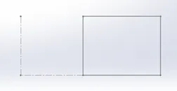
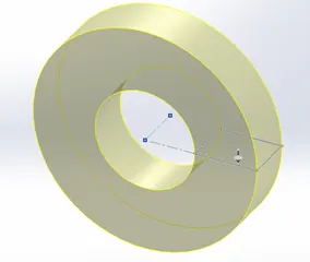
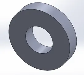
SHELL: Shell is feature that removes the material inside the solid body and keeps a small thickness to create a hollow body. Using this feature, we can make hollow body either completely closed or with open faces.
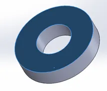
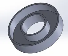
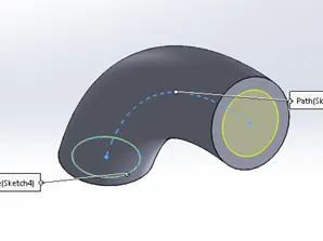
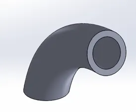
SWEEP BOSS/SWEEP CUT: This feature adds material or creates a boss, base or cut or surface using a profile along a path. The path must pierce through the midpoint of the profile. The profile must be a closed contour.
The sweep boss tool moves the profile along the path and adds material, creating a solid.
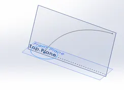
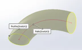
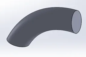
- The Sweep cut moves the profile along the path and removes material.
LOFT BOSS/LOFTED CUT: The Loft features is most important feature in (surface) modelling in solidworks. The loft feature creates a shape by making interpolation between multiple profiles or faces and with or without guided curves. This Feature is very useful to create complex surfaces.
- In Lofted boss the materials is added along the profile shapes and path.
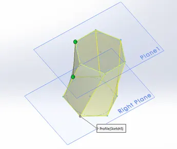
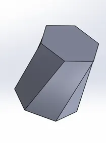
- In loft cut the materials are removed along the profile shapes and path.
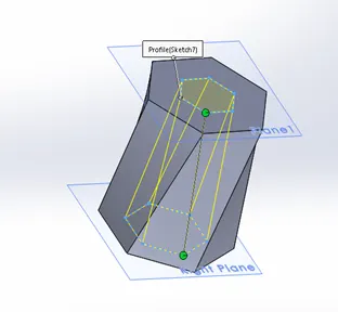
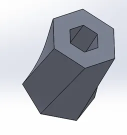
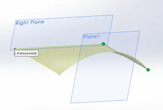
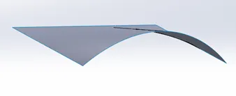
SURFACE LOFT: This feature is most similar to the Loft boss/cut. Here it creates complex surfaces by making interpolation between several profiles along the guided curves, it does not require the profile to be closed sketch.
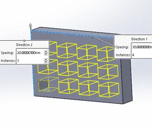
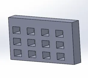
LINEAR PATTERN: This feature is used to create multiple instance of one or more feature or body that can be uniformly spaced along one or two linear paths. We can determine the number of instances, the distance between them, angle at which pattern to be created and several other parameters. Pattern instances can inherit the visual properties of the original Feature when the propagate visual property is selected in property manager.
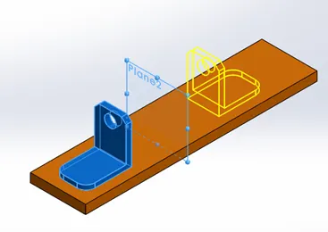
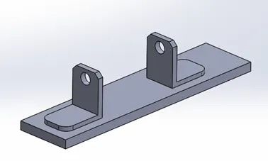
MIRROR: This tool is helpful In creating a copy of a feature, body mirrored about a face or plane. We can select the feature or faces that comprises the feature. Bodies to mirror, select a single body in a single body or multibody part to create a mirrored entity. Apply features to one or more multibody parts by selecting geometry pattern and using the feature scope to choose which body should include the feature
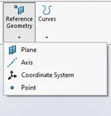
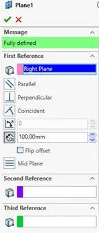
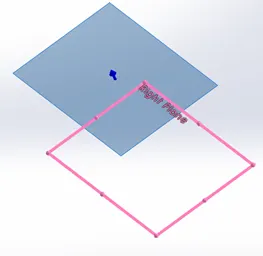
RFERENCE GEOMETRY: The reference geometry tool is used to create a plane or axis or point or a coordinate system respect to the selection of reference. This is a very handy and useful tool to create several features.
For Example:
> Planes are used in Lofts and sweeps.
> Axis is used in circular pattern.
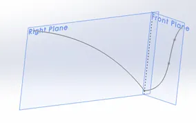
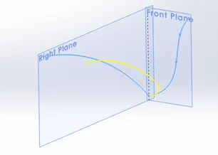
PROJECTED CURVE: This feature is used to project a curve onto a surface or to a model face to create a 3D curve, It is also used to create 3D curves but intersection of two extruded surfaces generated by creating sketches on two intersecting planes. We can create multiple closed or open contour projected curves from a single sketch. We can also use 3D sketches as a input for the projected curve tool. It does not support projections of intersecting curves.
MATE (assembly): Mates helps us to create a geometric relationship between the assembly components. By applying mates, we can either make the component fixed on its position or define the allowable direction of linear and rotational motion of the component at its location. We can move the component within its degree freedom, visualizing the assembly’s behaviour.
For Example:
- Coincident Mate forces two planar faces to become coplanar. It makes the faces move along one another but cannot be pulled apart
- Concentric mates forces two cylindrical surfaces to become concentric an makes the faces move along the same axis but cannot be moved away form the axis
All mates are solved at the same time, irrespective to the order of which the mates are applied, they are solved as a system together. We can supress the mates as we supress the features in part making.
As we discussed the various features, their application, properties and work under solidworks, let us see the application of the features in the chopper we built. As described in the flow chart lets discuss part by part.
Transmission belt: The Transmission belt is a single extruded body with fillets applied to its outer edges and Matte rubber appearance is used to the whole body.

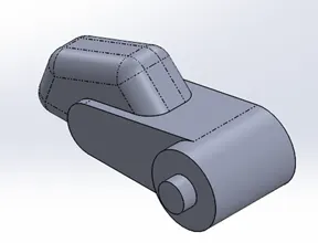
KICKSTAND: In the kickstand design we used 2D sketch drawing on additional plane and the sketch was used to create a lofted part and the dome feature was applied on both the end faces of the part. The end portion of the boss is flattened using a sketch and the spit tool to make contact with the ground to achieve the geometry, and we also used a extrude cut using a sketch on a reference plane, for the assembly purpose. An extruded cylindrical boss is created to join the cut parts and the fillet is applied to the edges of the cut and joints of the boss. This part is a Metal chrome part.
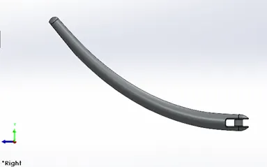
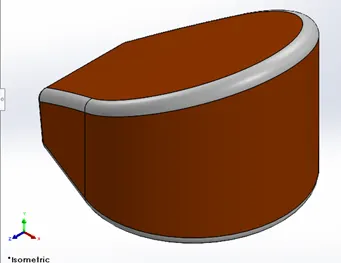
FRONT FENDER: Here we used Revolved Boss to create a revolved sketch using an axis. The both the edges are designed in the same body with the help of sketches and the split tool. The outer edges of the fender are filleted and the fender is made to appear in Sienna coloured metal component.
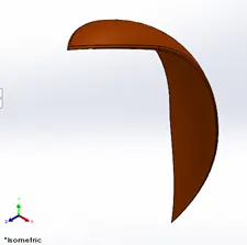
REAR FENDER: As the Front fender the same methods has been applied in the rear fender, as it was in the front the only difference between the two are the sizes of the fenders which varies accordingly to with the size of tyre. This part is also a metal part and painted Sienna which gives a bright orange colour.
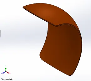
OIL TANK: The oil tank is created by two extruded sketches on Top and the Mid planes and combined to obtain the structure of the oil tank. Then a shell feature is used to make the part hollow and to make the edges round the fillet is applied to the edges of the part. Again, the metal body is painted with the same Sienna colour and the filleted edges are applied with white paint. During the process of Rendering there is an application of decals which we will see further ahead.
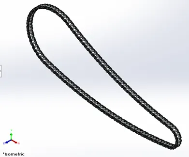
CHAIN LINK: For the first we have created a sketch to determine the path of the chain with the help of lines and curves. Then we created the front and back link which we saved as a block diagram. Bringing back the first set of front and back blocks we located them to follow the path and then simultaneously applied with the concentric relation to one of the joint of the path, then calculatedly began with the process of curve path arrangements from one joint to another by determining the angles and number of blocks required until the entire loop is completed. Finally, after sorting out the arrangements we mirrored the faces of the links to the pins in the block diagram with respect to the midplane. A fine finished chrome plate metal is used as appearance of the linked part.
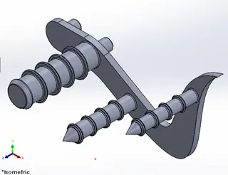
PEDAL: First we sketched on the front plane which is used to extrude for the base of the pedal with dimensioned holes for the foot rest and the pins which are extruded the second time. For the footrest a sketch is created on the top plane which is the revolved to make a 3D image. The outer edge of the foot rest is applied with dome and the edges and joints of the foot rest is filleted to avoid sharp cut edges, the front and rear extruded cylindrical parts are then applied with chamfer to obtain a proper finish. Then a circular pattern is extruded on each of the front extrudes later which are arranged with the use of linear pattern and fillet is applied to all the edges and the joints of the last pattern. This is also a metal part which is made to appeared on chrome metal finish.
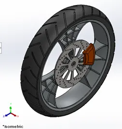
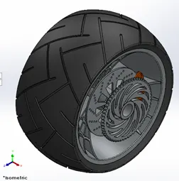
FRONT AND REAR WHEEL: The designing process of both the wheels are more similar with variations in their size of the wheel. A 2D sketch is created on the front plane which is then revolved. An extrude of the sketch in the midplane to create the part which is merged with the hub, to attain the spider web design o the spokes a sketch is made on the face of the extruded part with proper reference and construction geometry the sketches are cut extruded and then a circular pattern is made along the edge of the rim to make the other two spokes. Now we design the disc and the hub of the wheel on the same plane, offsetting it to an level and extruding it. To create the ventilation holes, we extruded the sketch made on the plane and made a linear pattern first and made a circular pattern along the edges of the disc. In addition to the disc we created a sprocket only on the rear wheel which is connected to the hub of the rear wheel. The entire wheel consists of five parts, to make a realistic look, different appearances are applied to different solid bodies. The Rim, Disc Rotor and the sprocket (only on the rear wheel) are Chrome metal finished, the tyres made to appear as matte rubber and the calipers are painted Sienna.
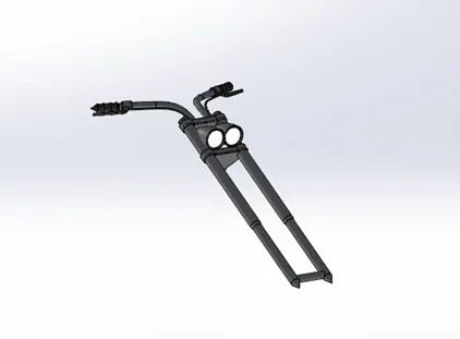
Front fork: The Front Fork consists of the front fork , head lights , handle bars , the grips, brake and clutch levers, and the wires. The easy way to create the front fork is to create the half of the fork and then mirror it to design the complete fork. The design is started by sketching the fork on the right plane and making a revolved boss. On the top circular face a sketch is made to create the upper portion of the triple clamp and it is linearly patterned to create the lower part. A semi cylindrical extrude is made to connect the upper deck and the mirrored side of the triple clamp. Another sketch is made on the front plane along the top of the handle bar facing down which is further revolved to form the head light. To make it hollow we extruded a sketch on the face of the headlight, the edges are filleted and a dome is applied to give a headlight curved look. We used two curves to form a projected curve and a cylindrical sweep is made along the projected curve which is the handlebar. To design the grips, we revolved a sketch on the front face of the handle bar and on the inner face of the handle bar we designed a sketch which is then extruded to create levers and fillet is applied to the sharp edges. Another projected curve is made to sweep the wires for the brake and clutch. Finally, we create a plane from which the other side of the fork is mirrored and the components are combined respectively. The headlight dome, the handlebar, the forks are polished chrome plate metal, where as the grips and the wires are glossy black finished. To give realistic lighting effect during render we applied area light to the face of the headlight.
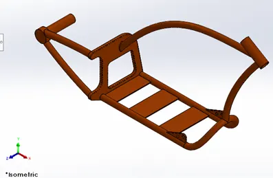
CHASSIS: The design of the chassis begins by drawing two projected curves to obtain the lower curved path of the block which is swept along the path and then the swept part is mirrored along the midplane to obtain the lower geometry. A new sketch is created at the open end of the swept geometry, which is then extruded and then another sketch is created on the face of the extruded part, which is then extrude cut and the base of the block is chamfered and the sharp edges of the block are filleted both on interior and exterior. Two more sweeps are created from the exterior face of the block and at the open ends of the sweeps a plane Is created and two extrudes are made with geometrical attachments required to join it with the sprocket. To design the upper rod of the chassis another sweep is made from the inner face of the block and split tool is used to remove the excess material. To make the chassis connect to the front fork a revolve part is created at the open ends of the chassis rods and using split tool the excessive materials are cut off. The bottom rods of the chassis are connected with some extruded geometry. Now to make attachments with the pedals and the kickstand some extrudes are made and the undesired parts are extruded out and the sharp edges are applied with desired fillets. A new plane is created for the purpose of assembly. The whose chassis is painted Sienna colour.
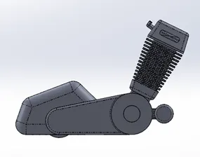
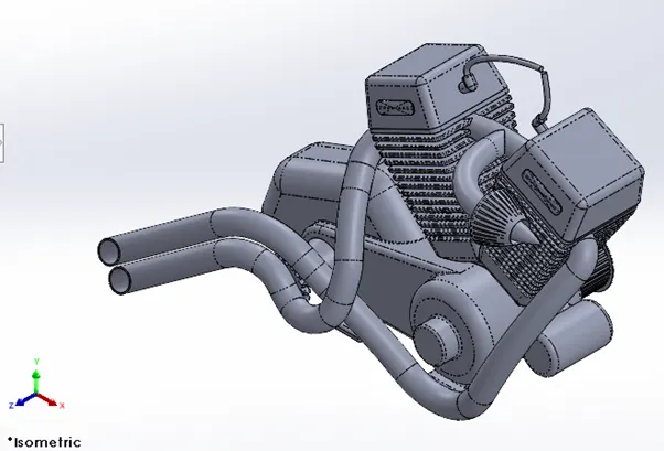
ENGINE MOTOR AND THE EXHAUST: First to design the base of the motor we made an extrude using a sketch on the front plane, two more boss extrudes are made using the same sketch to attain the proper shape of the motor. Another sketch is made on the front plane is extruded and applied with fillets to design the transmission part of the base. On the other side of the motor two revolves are made to make the arrangements of the transmission belt and the spokes are made using extrude and linear pattern around the circular region and the same process is used on the other revolved part, on the front of the revolves some extrude cuts are made to attain the desired shape. Another extruded boss is used to create the starter at the front of the motor. To design the cylinders a sketch is used to make three extrudes, fillets and chamfers are applied to the upper face of the cylinder to attain the desired shape. Using another sketch cut extrude is made and applied with fillet, which is the linearly patterned downwards to the cylinder to create the fin structures. another extrude is done for the spark plug. Mirror body tool is used to mirror the cylinder body for the twin cylinder. To make front gear for the chain link a cylindrical extrude is made followed by another one, on the face of the second cylindrical extrude an extrude cut is made and circular patterned along the edges of the cylinder to create the gear tooth. On the bottom face of the engine extrudes are made to design the stand which is used in the assembly part. Between the two cylinders a sweep, followed by another one and at the end of the second sweep an extrude is done with some filets and extruded cut on it to attain the shape of the air filter. To design the exhaust pipes two projected curves are made which are then made to join together using composite curve which is swept all the way from the starting face of engine towards the back according to the dimensions, and the same process is carried out for the second pipe. At last two different sweeps are made to design the wires from the top face of the spark plug. The whole engine is made to appear as chrome plate metal.
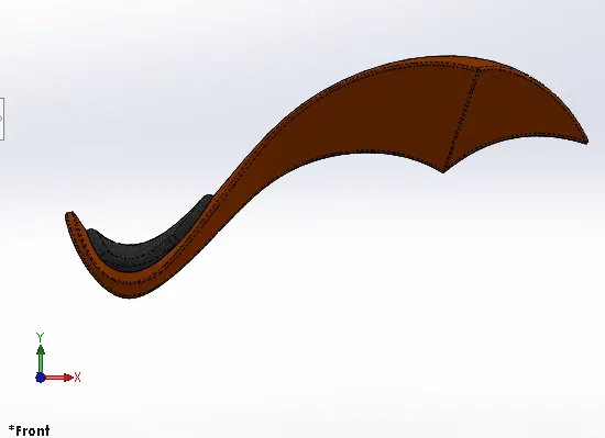
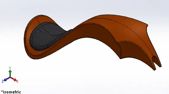
GAS TANK: To start the modelling of the gas tank we must know the features used in the surface section modelling. We start by creating additional reference plane and draw two sketches on it which is surface swept to obtain the basic layout of the gas tank, now the edge is surface trimmed to obtain the design of the tank, another reference plane is added to create a sketch that is further surface lofted as the front face of the gas tank. Now with the help of the boundary sweep feature the front and the side faces of the fuel tank are connected with the rear face. Mirroring the entire part and knitting them together we get the entire gas tank surface. Now to create the seats, surface extrude is made and fillets are applied to the sharp edge. The bottom of the gas tank is covered using surface loft and surface boundary features and all the surfaces are knit and combined to form a solid component. A new sketch is made in the front face of the tank to cut a ‘U’ section for the assembly of the gas tank with the chassis. All the sharp edges are filleted and a shell is created at the end to make it hollow. Sienna colour is applied to the whole tank and a grey cotton material is used for the seats. There are application decals to the gas tank which will be discussed in the rendering process.
ASSEMBLY:After completeing the designing of all the parts of the chopper the most important part is the assembly of the entire chopper to a single file begins. To start we begin by bringing the chassis first and using its plane and geometry as a base for the entire solid assembly. The second part we bring in is the engine, the base stand of the engine is matted coincident with the base of the chassis and then the planes of the engines are mated so to be fixed body and does not move, and at the last a distance mate is applied so that the part is fully defined. Then we bring the pedal in, the Pins in the pedals are mated with the holes in the chassis and coincident mates are applied to make the pedal part fixed Then the pedal is used to create another pedal on the other side using mirror option with defined properties of opposite side. Now we bring the kickstand in, first a coincident mate is applied to the holes made in the chassis and the cylindrical extrude in the kick stand. Now to define the angular movement of the kick stand, an angular mate is made is provided with the body so that there is no disturbance with the model. Now we bring the transmission belt in which is mated on the engine drivers to fully define this with the mates we provide an angle to make the joint coincident with the drivers, next we bring the oil tank in and which is directly placed and matted above the engine. Then we bring the rear wheel in and which is concentrically matted with the chassis and the hub of the wheel, the planes are matted accordingly and a parallel mate is applied to fully define the sketch, now the rear fender is brought and mated above the rear wheel, next we bring the chain link and we started with the width mate between the chain link parts and the sprockets in the rear wheel and the engine, now we bring in the gas tank and is fixed using a distance mate and parallel mate with respect to the chassis , now the front fork is brought in and mated coincidently with the upper part of the chassis and a width mate is applied to retain the vertical motion of the fork of the fork. Now for the turning angle of the front of chopper an angle mate with certain limit is applied between the fork and chassis, finally front wheel is attached with the front fork as it was attached in case of the rear wheel, at last the front fender is placed above the front wheel.
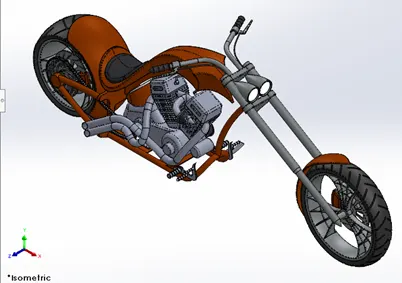
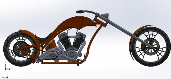
RENDERING: The final step of modelling the chopper is to make it look realistic, as we have already discussed the uses of the rendering process of the model, here we try to make it more realistic we started with checking whether the appearance is applied to all the parts , then to make it look more stylish we add some decals on some parts like the gas tank , oil tank and the rear fender. Now we try to make it realistic by giving it a camera view setting, the desired lights and the focal distance, creating a angle of view and saving the camera angle which gave the realistic view to the chopper. Now we take our assembly file into solidworks visualize where we start making the product more and more realistic with adding the background changing and adjusting the brightness, shadow density and the gamma levels according to the different requirements of the different backgrounds changing the colour of the model and checking what suits the best with the background until we get the desired and astonishing product ready.