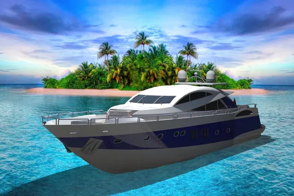
Radar Mast & Final Assembly of Yacht
ASSEMBLY

REPORT ON MODELLING YACHT
MODELLING OF LUXURY YACHT
INTRODUCTION
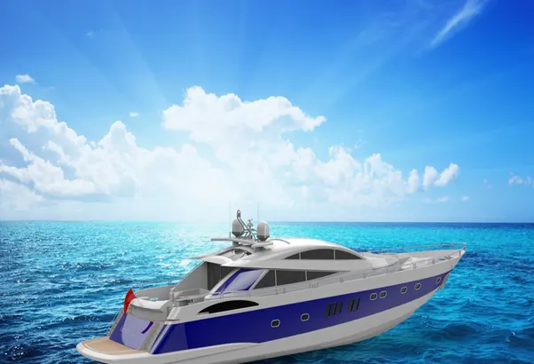
In this project tutorial we are to learn how to 3D model various parts of a Luxury Yacht and assemble to model a complete one
The various parts of Yacht we designed are
- Propeller
- Radar
- Hull
- Garage door
- Front seats
- Middle seats
- Rear Seats
- Superstructure and
- Radar mast
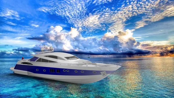
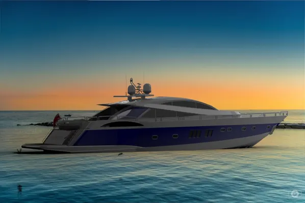
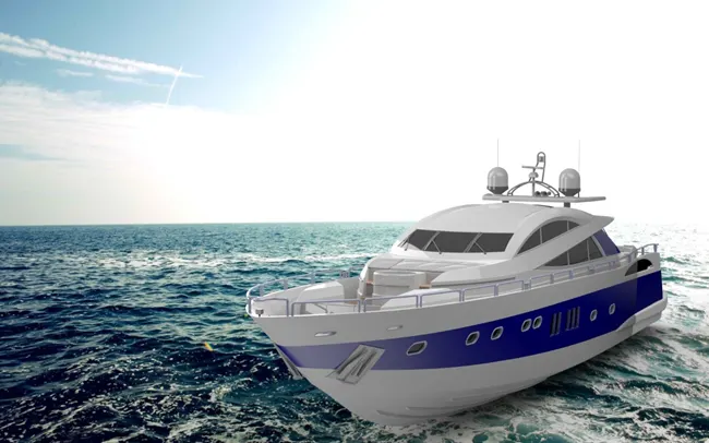
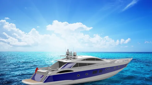
After Designing all separate parts of the Yacht, we worked on assembling all the parts and Photo render of the Luxury yacht to get a complete and realistic view of the Yacht.
DESIGN APPROACH
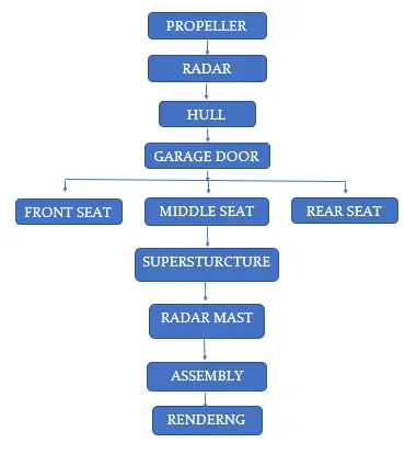
Starting from the design of Propeller blades till the photorealistic render using Solidworks visualize has been described step by step in the flow chart.
Let’s discuss the various features and properties used in the entire model to design different parts
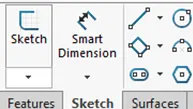
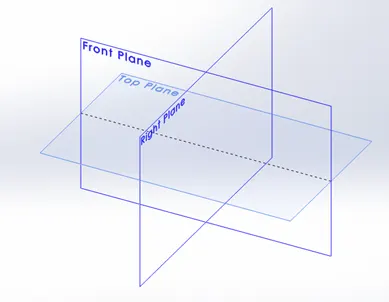
1.SKETCH: The sketch forms the basic structure or blueprint for the 3d component. It may be either 2D or 3D sketches. In 2D we select the plane on which we are up to sketch and select the 2D sketch option in the sketch tab in the Command manager. Once the sketch is completed it may be converted into 3D components or surfaces and etc. In 2D we’ll be able to sketch along two axes respect to the plane or surface we are sketching on. On the other hand, 3D sketching enables us to sketch over 3 axes independent of particular plane or surface. it does not require any surfaces or planes to be defined to sketch on.
2.EXTRUDE: The EXTRUDE is the most basic of all features in Solidworks, that is mostly used in Solidworks to convert a completely closed sketch into a 3D solid component or add material along a straight path. It is classified under sketched feature as it requires a closed sketch to enable this feature. Once a closed sketch has been created exit the sketch and go to features tab in the Command Manager and select the Extrude Boss/Base command, select the sketch to be extruded. The property manager in the extrude option allows us to make several changes such as dept depth direction of extrude, starting and ending location for extrude and many other parameters
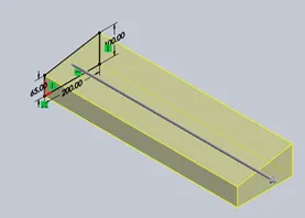
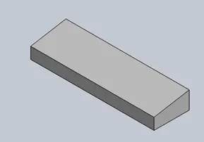
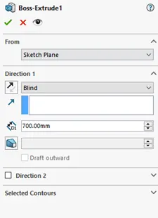
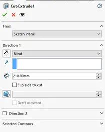
Extrude Cut: This feature is similar to the Extrude Boss/Base, this requires a closed sketch to remove the materials respect to the dimensions of sketch. It also allows us to modify various parameters in the property manager.
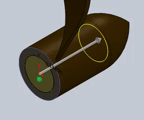
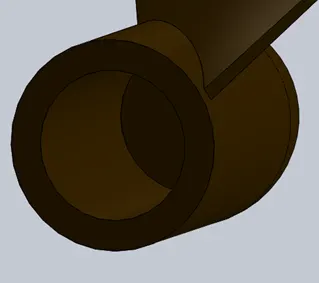
REVOLVED BOSS: This feature is used to create a solid component revolving the closed sketch around desired axis. It is a sketched feature uses a closed sketch to add materials. It uses the sketch and the axis through which the sketch is to be created into a solid part, thus during the sketching process it is very important to determine or draw an axis, respect to which the sketch should be revolve and form solid body. The property manager of the Revolved Boss features allows us to modify angle up to which the material is to be added, direction of revolve and other several parameters.
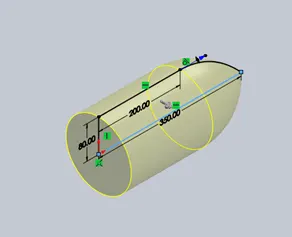
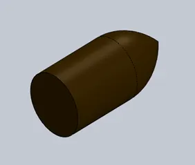
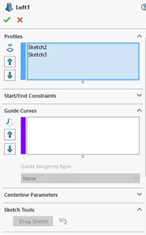
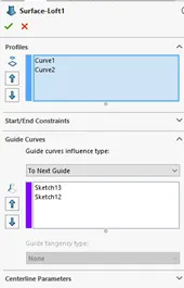
LOFT BOSS/LOFTED CUT: The Loft features is most important feature in (surface) modelling in solidworks. The loft feature creates a shape by making transitions between multiple profiles on different planes and with or without guided curves. This Feature is very useful while creating complex surfaces. It uses two or more different sketches on different planes to create a solid body transiting along the shape of the sketches and about the guide curve.
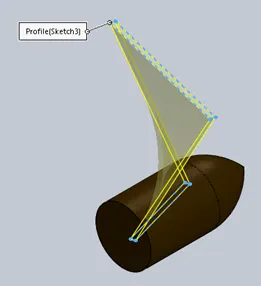
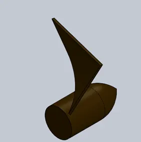
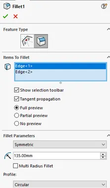
FILLETS: The fillets are used to make a sharp edge of a 3D component to a rounded smooth edge. It does not require any sketched entities to use Fillet feature, rather it requires edges to create fillets and thus it is classified under applied features. The fillet creates a rounded edge by the means of either removing the material, depending on whether the edge in internal or external. It makes the rounded edge tangent to the surfaces of which the fillet is made. We cannot create fillets of different size at single fillet. It is best practice to create larger fillets first and follow the smaller ones. The property manager of the fillet tool enables us to modify several parameters of the fillet created like symmetric or asymmetric fillet and etc.
SWEEP BOSS/SWEEP CUT: This feature adds material or creates a boss, base or cut or surface using a profile along a path. The path must pierce through the midpoint of the profile. The profile must be a closed contour.
- The sweep boss tool moves the profile along the path and adds material, creating a solid body.
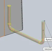
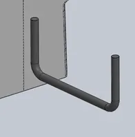
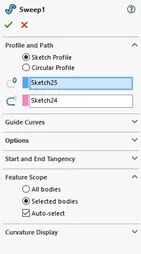
- The Sweep cut moves the profile along the path and removes material.
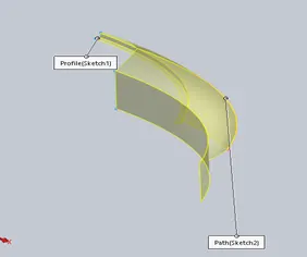
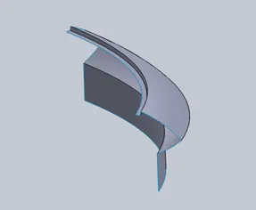
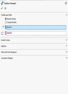
SURFACE SWEEP: The surface sweep option is more similar to the swept boss/cut, here it sweeps the profile along the path to create a surface, the property manager helps us to modify several parameters like profile orientation, tangency of the sweep and etc.
LOFT BOSS/LOFTED CUT: The Loft features is most important feature in (surface) modelling in solidworks. The loft feature creates a shape by making interpolation between multiple profiles or faces and with or without guided curves. This Feature is very useful to create complex surfaces.
- In Lofted boss the materials is added along the profile shapes and path
- In loft cut the materials are removed along the profile shapes and path
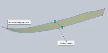
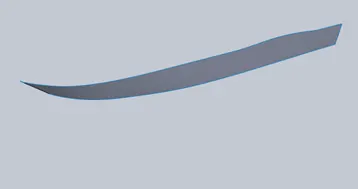
LOFTED SURFACE: This feature is most similar to the Loft boss/cut. Here it creates complex surfaces by making interpolation between several profiles along the guided curves, it does not require the profile to be closed sketch.
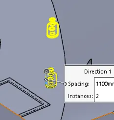
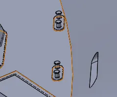
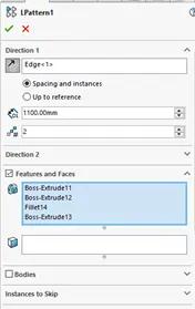
LINEAR PATTERN: This feature is used to create multiple instance of one or more feature or body that can be uniformly spaced along one or two linear paths. We can determine the number of instances, the distance between them, angle at which pattern to be created and several other parameters. Pattern instances can inherit the visual properties of the original Feature when the propagate visual property is selected in property manager.
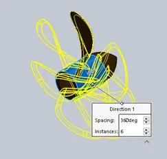
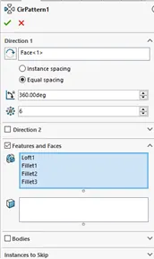
Circular pattern: This feature is used to make instances of a feature or a body along a circular path. The property manager of circular pattern helps us to modify the no of instances, angle and etc.
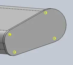
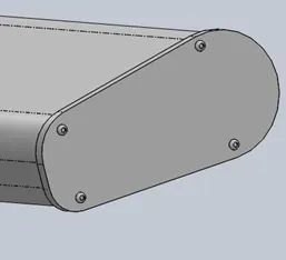
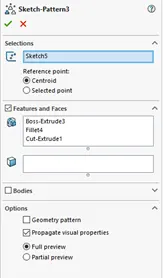
SKETCH DDRIVE PATTERN: The sketch driven pattern creates copies of existing features and places them wherever we’ve added a point in a sketch. All it takes is a sketch created specifically to place instances of a feature.
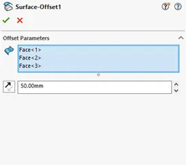
SURFACE OFFSET The Offset Surface tool creates a new surface body from an existing set of faces. The faces may be solid or surface faces. It creates a new instance of the existing face in desired position.
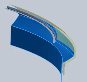
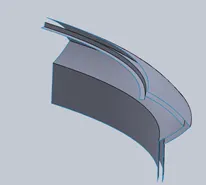
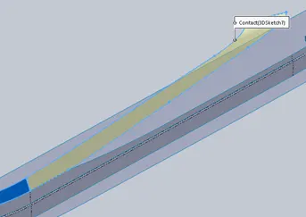
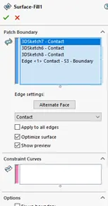
FILLED SURFACE The Filled Surface feature constructs a surface patch with any number of sides, within a boundary defined by existing model edges, sketches, or curves, including composite curves. You can use this feature to construct a surface to fill a gap in a model, close complex faces.
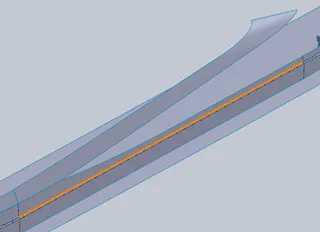
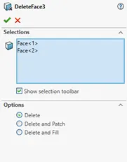
DELETE FACE The delete face option is used to delete the unwanted surfaces in the design. There are few options available in the property manager of the delete face through which we can either only delete a face, or extend the edges of the face to intersect at a point after deletion of the face, or to delete and fill the surface.
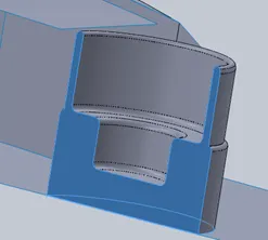
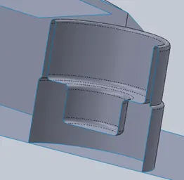
SURFACE EXTEND this feature is to extend the edge of the surface. You can extend a surface by selecting an edge, multiple edges, or a face.
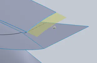
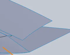
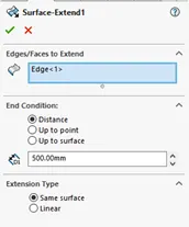
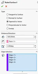
RULED SURFACE This tool is similar to the surface ,the Ruled Surface command creates surfaces that extend out in a specified direction from selected edges. In other words, it creates or extends the edge tangent to the surface of the edge. It is used to extend a edge of a complex surface.
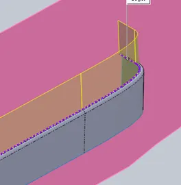
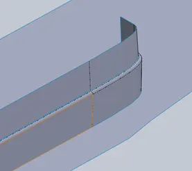
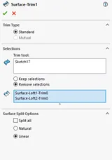
TRIM SURFACE This feature is used to trim the surfaces, and provides two modes Standard and Mutual. In Standard mode, a single selection is defined as a Trim Tool, and target surfaces are trimmed accordingly. In Mutual mode, multiple surfaces are trimmed with respect to each other.
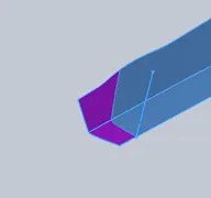
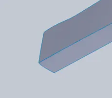
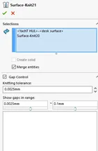
KNIT SURFACE Knit surface is the most commonly used feature in creating a solid body in SOLIDWORKS. It is a tool that can combine two or more surface into one. You can select the “create solid” checkbox from the top of knit surface Property Manager. For this option to be enabled, you must select the surfaces first and make sure that these surfaces are enclosed or form a closed volume.
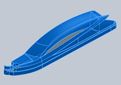
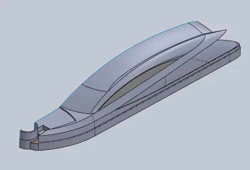
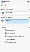
MIRROR: This tool is helpful In creating a copy of a feature, body mirrored about a face or plane. We can select the feature or faces that comprises the feature. Bodies to mirror, select a single body in a single body or multibody part to create a mirrored entity. Apply features to one or more multibody parts by selecting geometry pattern and using the feature scope to choose which body should include the feature.
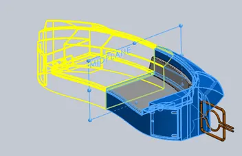
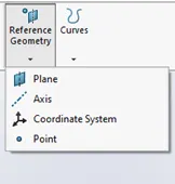
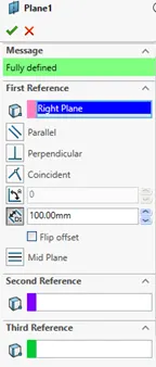
RFERENCE GEOMETRY: The reference geometry tool is used to create a plane or axis or point or a coordinate system respect to the selection of reference. This is a very handy and useful tool to create several features.
For Example:
> Planes are used in Lofts and sweeps.
> Axis is used in circular pattern.
As we discussed the various features, their application, properties and work under solidworks, let us see the application of the features in the YACHT we built. As described in the flow chart lets discuss part by part.
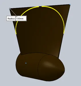
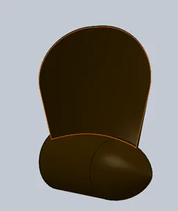
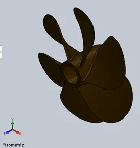
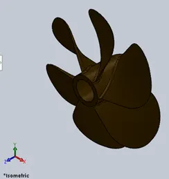
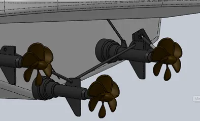
PROPELLOR: The propellor is a revolved boss of a sketch on which a loft is made to create the propellor blades. An extrude cut is made to attach the propellor to the hull during the assembly. The edge of the propellor blade is applied with some fillets and then the blades of the propellor are circularly patterned. A Brown colour appearance is applied to the whole propellor.
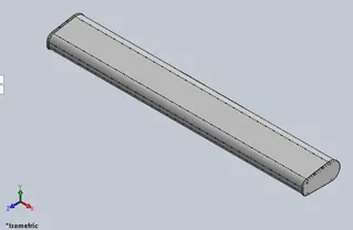
Radar: To design the radar first we made a extrude boss using a sketch on the midplane. After applying few fillets, we made another extrude on the other side of the extruded boss. Again, after applying some fillets we made another extrude for screws. Applying some fillets to the edges of the screw we made an extrude cut on the screw face, then the screws were sketch patterned. Then the whole part is mirrored about the midplane. An extrude cut is made at the bottom portion of the radar to attach it with the radar mast during assembly. A logo naming" YACHTTUTORIAL " is made at the backside of the radar using split line. White colour is applied to the radar and to highlight the logo blue colour is applied to the text.
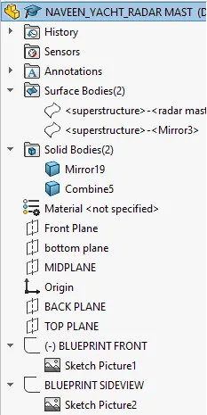
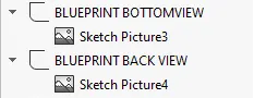
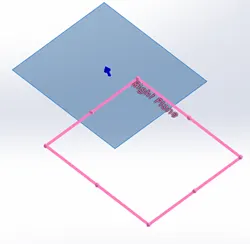
BLUEPRINT SETUP: To setup the blueprint we first created a sketch on the front plane, then by inserting sketch picture we brought the front blue print and by giving perfect dimensions and renamed the sketch as blueprint front view. We continued the same process to insert the blueprint of side view and bottom view on right and top plane and renamed as blueprint sideview and bottom view respectively. To insert the blueprint of top View and back view we created two new planes by offsetting the front and top plane to a distance. Then we created new sketches on the planes and inserted the blueprint images respectively and by renaming the sketches as blueprint top view and blueprint back side view, we finished the blueprint setup.
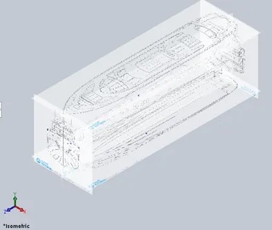
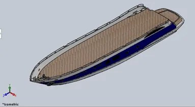
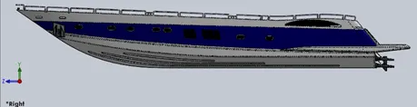
HULL: The hull is created using several swept and lofted surfaces. First, we started designing in the blueprint setup, and made two projected curves from 4 sketches respectively. With help of two new sketches as guided curves a surface loft is made, to Create the upper right surface of the hull. With help of two new sketches another surface loft is made and trimmed to from the required shape of the lower part. Then we made surface loft and surface extrude and after surface trimming the surfaces, we were able to create the back side of the hull. Made Two surface fills to create a solid body and applied Shell to the solid body then we made two extrude boss from a sketch made on the midplane to form the structure of the disk surface and the rear surface of the hull. After applying some fillets and chamfers to the sharp edges, we made some extrude cuts on the outs surface of the hull to create the window portion. To create the window border, we created new plane on each window and made a swept boss using a sketch on the plane as profile and a 3d sketch of the outline of the window as the path. To create the steps, we made a extrude cut from a sketch on the top plane and made some extrude bosses to get the staircase structure. Then we made some extrudes and applied chamfers to them at the bottom surface of the hull to add details. Using boss extrude feature we made some structures and linearly patterned them on the hull surface. To create the handle for the stair case we made a sweep at the rear. Succeeding the sweep, we made a reference sketch for the rail. With help of the rail reference and a new sketch, we made a projected curve and made a sweep to create the structure of the rail. To design the trim tabs, we first made an extrudes from a sketch on the back surface and revolve on it. After applying some fillets and chamfers to the sharp edges, we worked on the propellor shaft. For propellor shaft first we made a revolve from a sketch on the midplane, and made some extrude boss to design the fins. After applying some fillets, the propellor shaft with fins is linearly patterned. The connecting rod between the fins of two propellor shafts is created by a sweep of a sketch made in new plane at the centre of the fin. For the anchor first we made an extrude boss from a sketch on the midplane, then created a plane with the vertices of the extruded boss as references, then created another plane by offsetting the newly created plane for a distance. Then we made a sketch on the offset plane and extruded it. Keeping it as base we made some extrudes and applied chamfers to them. Mirroring the half of the anchor we were able to obtain the structure of anchor. Few extrude cuts were made at the rear portion of the hull for garage. Then the extrude cut solid body is save as separate solid part for designing of the garage door. The upper desk surface is offset for the reference of superstructure design. Finally, we mirrored the whole structure about the mid plane and obtained the whole structure of the hull. The Hull gets dual colour with blue and white combination, windows are painted black. The propellers shafts are painted grey. We brought some wooden decals for the desk surface and the staircase using photo-view 360.
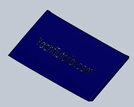
GARAGE DOOR: During the process of modelling the hull me made a split body and saved it as a separate solid part. We opened the solid part and start designing on it. First, we made a sketch on the surface of the solid part and extruded out the unwanted portion. Using shell tool, we made a cut. After applying few fillets, we made a small extrude cut on the upper edge on side face to attach the door with the hull. Then the part is mirrored about midplane. The same blue colour which is applied to the hull is applied to the garage door. The logo" yacht tutorial " is extrude. Cut on the outer side of the door.
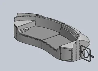
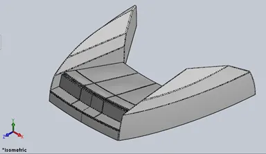
FRONT SEAT: For the front seat, first we started the design in the blueprint setup and imported the desk surface of the hull. A lofted surface is made and following that, a surface extrude is made using sketches on the hull surface, to design the side portions of the front seat. After making some surface trims and a surface fill, another lofted surface is made to close the surface body. New surface fill is made to cover the bottom surface. All the surfaces are knit together to form a solid body. A revolve is made from the solid body to a distance to get contact with the midplane. On Top of the revolve surface another revolve of angle is created to form the structure of the cushion or pillow. After applying few fillets, the solid bodies are mirrored about the midplane. Fillets and domes are applied to the cushion surface and the whole front seat is coloured white.
MIDDLE SEATS: To design the middle seats, we started the design in the blueprint setup, then we imported the desk surface of the hull and create a sketch on the desk surface with suitable dimensions. Then two extrude bosses are made simultaneously to create the lower part of the middle seats. A new plane is created with the vertices of the extrude surface as the reference. A new sketch is made on the newly created plane and extruded to form the structure of the cushion. Another plane is created on the surface of the cushion and an extrude create the vertical cushion. After applying chamfers and fillets to the edges, we mirrored the bodies about the midplane. A extrude is made from the sketch created on the deck surface, on the top of the extruded surface another sketch is made and extruded. Another extrude is made from the sketch on the face of last extruded part. To give the table some textures we made some extrude cuts. The seat base is coloured as white and the cushions are coloured as light grey. The table is dark grey painted and the top surface of the table is textured with brown and white colour.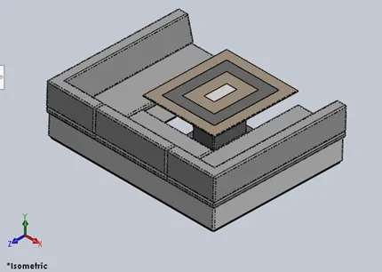
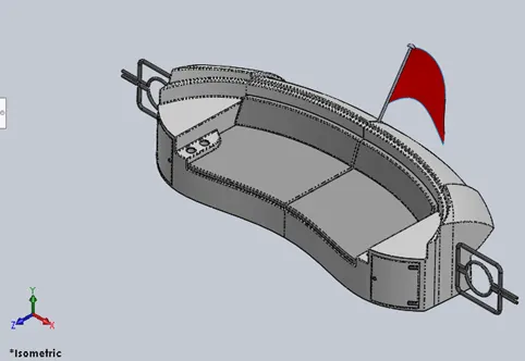
REAR SEATS: The designing process of the rear seats begins in the blueprint setup. A sketch with two splines and some lines is created. A new plane is created to the point where the two splines intersect. Now a sketch is made on the plane and a surface sweep is made with the first sketch as the profile and second one as the path. After offsetting the surface, we trimmed the excess surfaces with a sketch on the new plane as the trim tool. We made a ruled surface at the outer end of the surface and made another surface trim with the newly created sketch on the desk surface as the trim tool. Two new planes are created and two sketches are made respectively with which a swept surface is created followed by the surface extend from the swept surface. With some surface trims we were able to remove the excess surfaces. Followingly we made a surface extrude form the sketch on the desk surface. After trimming the excess surfaces on the extruded surface we made a loft covering the open edges on the sides of the seat with some 3d sketches. Another two new lofts are made at the bottom face of the seat and all the surfaces are knit together to form a solid component. An extruded boss is made from the sketch on the desk surface, followingly another extrude is made from the sketch on the surface of the previously extruded part. Then we made a extrude cut form the front plane to the front side of the seat to create the look of the shelf. By making some extrudes we were able to create the hinges and the keyhole for the shelf. Then we made two extrudes one on another from the sketches on the plane offset from the surface of the seat to create the cushion. After applying some fillets and chamfers to the edges we started designing the tailgate by creating few swept bosses. Finally, we mirrored all the solid components about the midplane and made a revolve from the sketch on the midplane to create the flag post. For the flag we created 4 -3d sketched splines to connect each other and made a loft surface. The rear seat is coloured white, the cushions and the flag pole are painted light grey, the flag is red coloured and the tail gates are painted as dark grey.
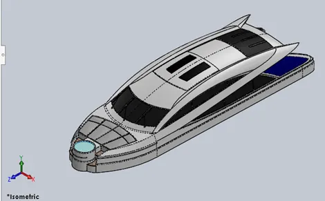
SUPERSTRUCTURE: We started designing on the blueprint setup and imported the hull desk surface. A surface extrude is made from the sketch on the desk surface. Then we created a new plane and made a swept surface on the upper edge of the previous sweep. After applying fillet to the edge, we created a ruled surface on the edges of the last sweep and trimmed the surface using a new sketch on the midplane as the trim tool. With the help of two new sketches, we created a projected curve followingly another projected curve is created from another two different sketches. Two surface lofts are made using the projected curves. Made a sweep for the border of the window, to create the window a plane is created in the path of the sweep and a sketch is made on the plane with which swept surface is created along the border of the window. A surface extrude is made from midplane through the top of the window. The excessive surfaces are trimmed and another surface loft using a 3d sketch and the sweep behind the window is made. To design the upper surface of the superstructure, two new projected curves are created and they were used to create the lofted surface. To create the roof of the superstructure we created a sketch on the midplane. Three-3d sketches were created connecting the surface and the sketch on the midplane. A surface loft is made along the sketch and the projected surface. Followingly a 3d sketch is created and a lofted surface is created for the windshield of the superstructure. From the bottom surface of the upper window, we made a ruled surface and trimmed it, adding some lofted surface to the open edges, we designed the upper window. We made some surface extrude at the rear end of the roof and trimmed it to fill the gaps on the surfaces. Then we knit all outer edges. Two new surfaces were extruded from the desk surface and the excess portions of the surfaces are trimmed out. Then keeping the lower window border as trim tool we made a surface trim and knit all the surfaces. A extrude of the sketch from the midplane is created and the excess surfaces are trimmed out. The front surface is trimmed with the help of a sketch on the top plane, and made some surface sweeps to make the base of the front cushions. We made a boss extrude from the desk to create Jacuzzi, then made a extrude cut and deleted a face. To create front step we made few surface extrudes and trimmed then to obtain the shape. After deleting the excess surfaces on the jacuzzi structure, we made a surface extrude form the bottom plane to create face covering the open side of the superstructure., then by knitting all the surfaces we formed a solid body. To create the front cushion, we created new plane by offsetting the surface of base for cushion. Then we made some extrude boss and made a extrude cut from top plane. We applied few fillets to the edges and made a dome on the upper surface of the pillows (or) cushion. After creating few sketches for the handles on front, rear of superstructure and on the jacuzzi, we made few swept surfaces to complete it. We made a extrude cut on the back surface of the superstructure to design the doors. Another few extrude cuts are made for the detailing purpose of the windshield, followingly few extrude cuts are made to complete the detailing. Then few extrude cuts and extruded bosses were made to detail the roof of the superstructure. Likely with few extrude cuts and extrude bossed we added some details to both windows. Then a surface extrude is made from the midplane to act as water layer on the jacuzzi pool. All the solid bodies and the surfaces are mirrored about the midplane. A surface offset is made from the surface on the roof for the designing purpose of Radar mast. Few extrudes were made for the wipers on the windshield, and few chamfers, extrude cuts and fillets were applied. For connecting rod on the wipers, we made few swept bodies. The whole superstructure is painted with white colour. The front cushions and the window borders are light grey coloured, applied a transparent nature and light cyan colour for the surface acting as water on the jacuzzi. The all the windows are painted black. We applied a custom grey colour for the handles. Then we imported some decals for the step surfaces. Blue colour is applied to the rear surface of the superstructure.
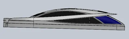
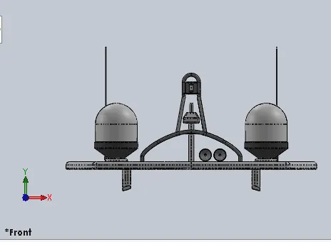
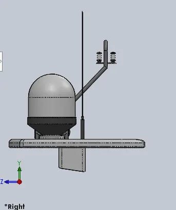
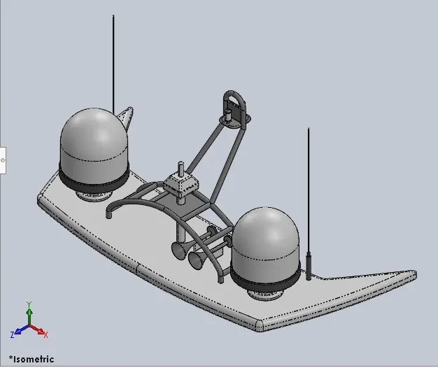
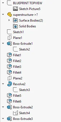
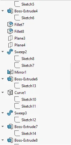
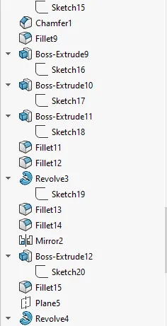
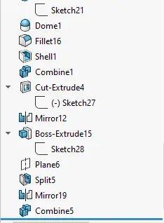
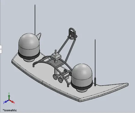
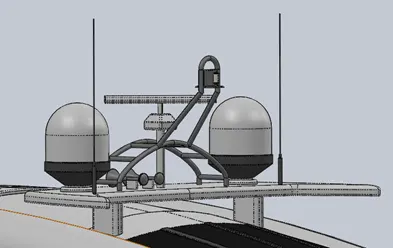
RADAR MAST: We started or design on the Blueprint setup. Then we made a sketch on the midplane for reference for a new plane. We made extrude boss from a sketch on the new plane for the base of radar mast. A new plane is created by offsetting the front plane, and a sketch is made and revolved for the radar. Few fillets were applied to the sharp edges. Using sketch on base surface, extrude bosses are made on one another near the radar for the antenna. Then we made several swept bosses for the mast. We created the part holding the radar by three extrudes on one another from the base surface. Few fillets and chamfers were applied to the edges. An extruded boss is created for the stand for hazard lights, following a revolve is made on the stand for the light. After applying some fillets, the light and the stand is mirrored. A extrude is made from the bottom surface of the base to connect with the surface offset from the superstructure. We created a new plane by offsetting the midplane. Then we revolved a sketch made on the new plane for the horn, followingly a shell is applied to the front face of the horn. Then we made an extrude from the base to connect the horn. After applying a dome and few fillets, we mirrored the horn to create another instance. Then the whole solid body is mirrored about the midplane. We applied white colour to the whole body. A custom dark grey is applied to the bottom of the antenna and the bottom of radar, the mast and the horn were painted with custom light grey, the lights are coloured as custom light yellow.
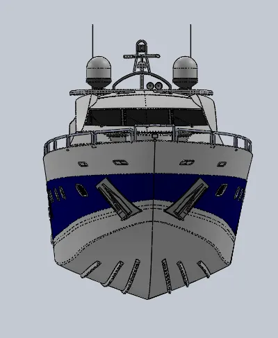
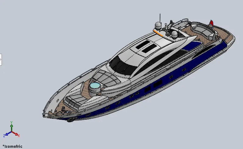
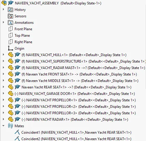
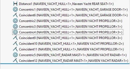
ASSEMBLY: For the assembly, we created a new assembly document in the solidworks. Then we imported the hull to get automatically fixed. Then we imported the superstructure, Front seat and the middle seat one by one which gets automatically fixed to the hull’s desk surface. Then the rear seat is imported. After adding some coincident mates between the rear seat and the hull’s desk and midplane, after applying a distance mate with the end point of the desk to the end point of the rear seat, we placed the rear seat on perfect position. By importing the garage door, we added coincident and a concentric mate with the extruded part on the hull. The we imported the propellor blade thrice and applied coincident and concentric mates with end of the propellor shafts. Finally, after importing the radar and applying concentric and coincident mates with the radar mast we completed the assembly.
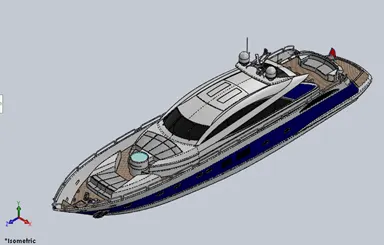
RENDERING The final step of modelling the Yacht is to make it look realistic, we try to make it more realistic by checking whether the appearance is applied to all the parts, the decals are imported properly. Now we try to make it realistic by giving it a camera view setting, the desired lights and the focal distance, creating an angle of view and saving the camera angle which gave the realistic view to the yacht. Now, we take our assembly file into solidworks visualize where we start making the product more and more realistic with adding the backplates changing and adjusting the brightness, shadow density and the gamma levels to make the yacht to look more realistic. We adjusted the environment to match the reflections and lights fall on the yacht with the backplate, and after checking whether all parameters suit the background, we started the render to get realistic image of the yacht