Week 7 Challenge - Assembly Workbench
Objective;
- To create 3d components using the given 2d drawings
- Assemble the parts inside a product as mentioned in the question
- Generate 2d drawings for all individual parts and the whole assembly
Assembly Workbench
Assembly is a workbench used to handle multiple part files that represent components inside a product file . The components are linked to one another in appropriate positions using various tools such as various constrains, manipulation commands and etc. There are two different approaches to create a complete assembly.
- Top - Down approach and
- Bottom-up approach
Top-Down Approach
In this approach all the geometries are created inside the assembly workbench. All geometries created are in the context of an assembly and so it is also called as “in-context design).
Bottom-Up Approach
In this method each parts are created separately not in an assembly workbench. In this approach all the components should be designed carefully using correct dimensions so they fit in their position properly during assembly.
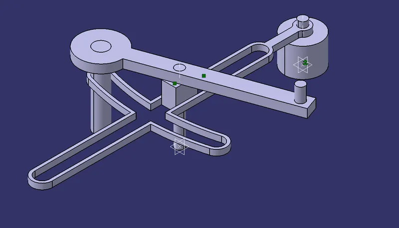
I followed this (Botton-up) approach to create both the assembly products, where I designed all the parts individually and inserted them inside a product and assembled them.
Parts creation
- All the sketches were created using the positioned sketch command
- All the sketches are created using appropriate dimensions mentioned in the given 2d drawing
- All the construction elements are created under the geometrical set and the part body consists all the solid features
Assembly process
Steps
- Begin the assembly process by opening the assembly workbench (Start- Mechanical Design- Assembly Design)
- Bring all the relevant parts inside the assembly workbench under a product file (Insert-Existing components-and select the product under which the component has to be placed)
- Create Reference axes where ever required in individual parts to ensure proper constraint position
- Publish the Reference Planes, axes, and the centre reference point to ease the assembly process
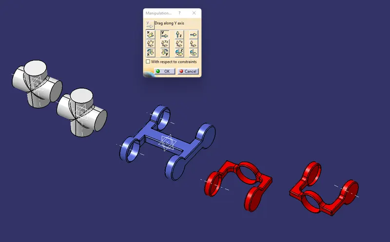
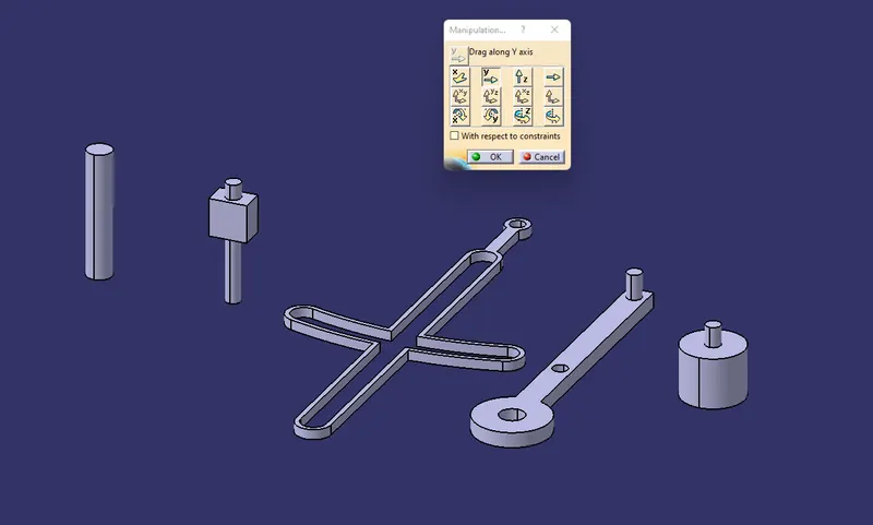
- Use “Manipulation Tool” to rotate the component to make the constraining process easy
- Make the reference component fixed
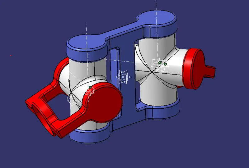
- Use appropriate Constraint Command to link the other parts to the reference part as mentioned in the given drawing
Drafting
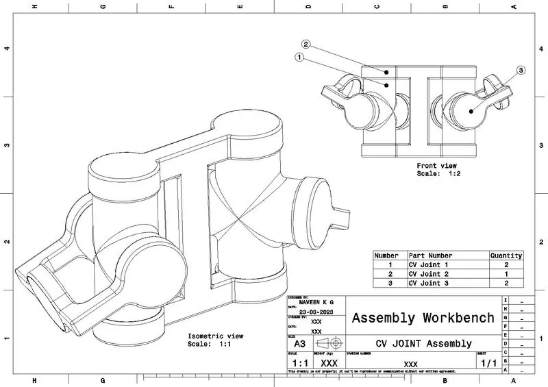
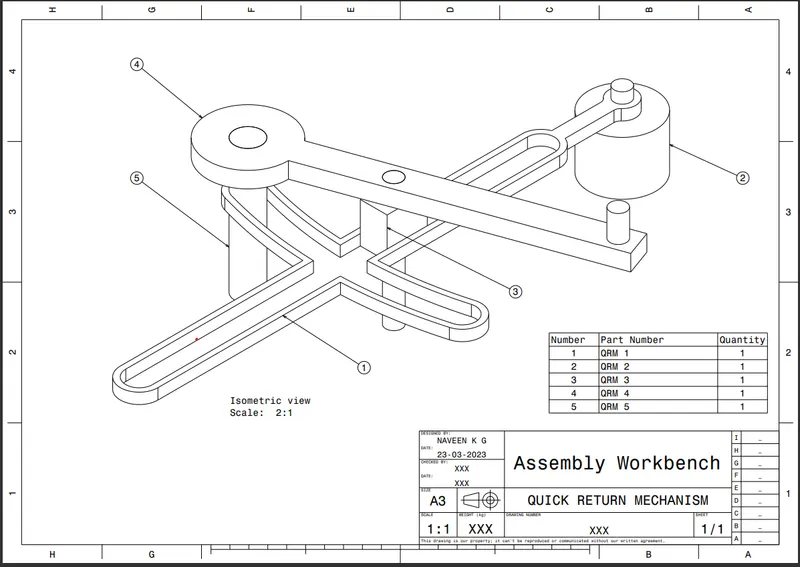
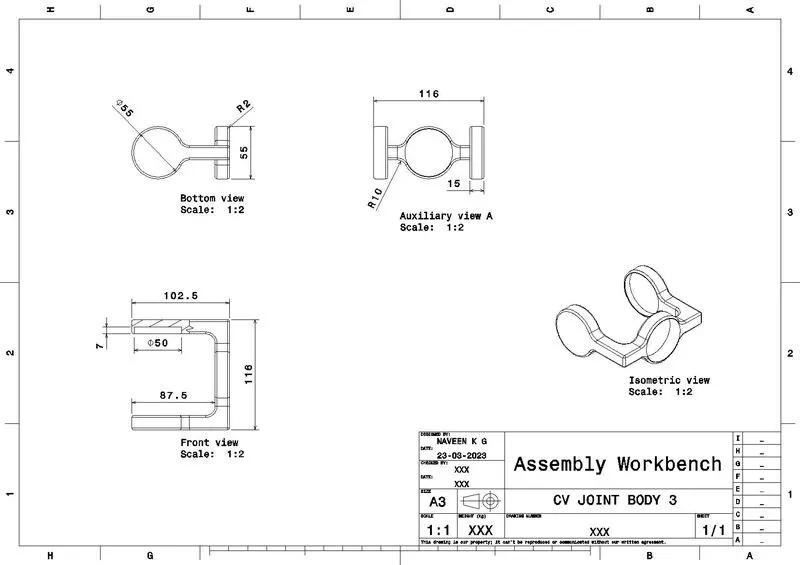
- After completing each and every component 2D drawing is created
- Opened a new Drafting workbench (File-New-Drawing)
- Imported Frame and title Block after changing working view to the Sheet background edit mode
- Projected front and isometric views of the CATPart using the “front view” and “isometric view” view command in the “Projection toolbar”
- Used Front view as a parent and projected top and side views using “projection view” command
- Inserted cut section view in complex locations to display the hidden inner dimension using “Offset section view” command
- Using “ Dimensions” command mentioned all the necessary dimensions of both parts and the assembly
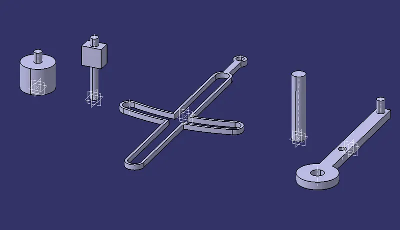
PRODUCT -1 (QUICK RETURN MECHANISM)
PART 1.1
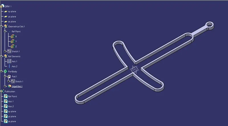
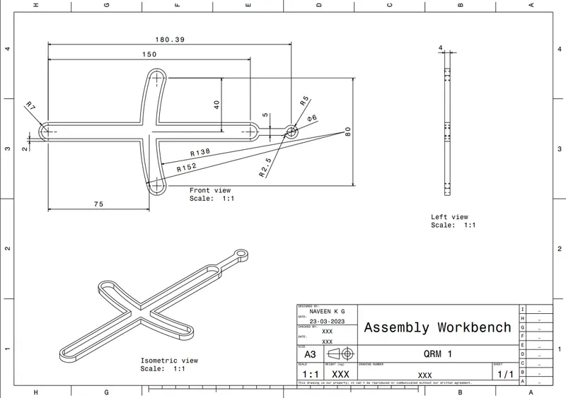
PART 1.2
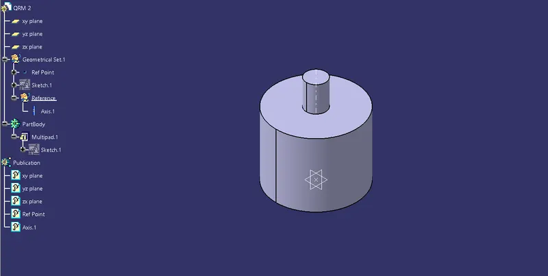
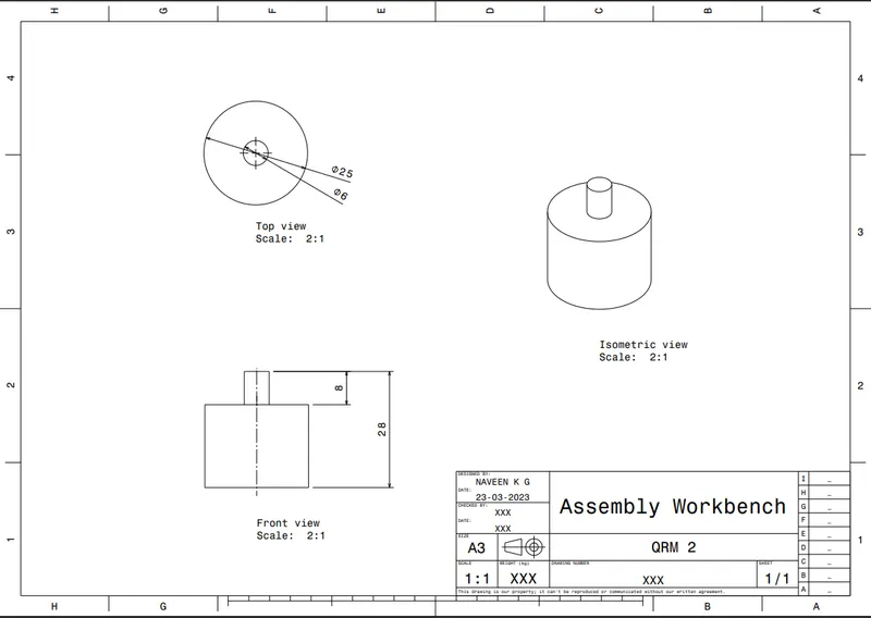
PART 1.3
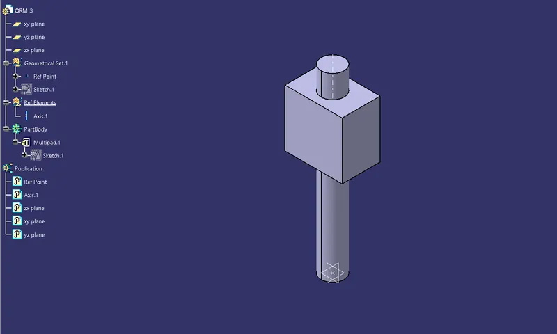
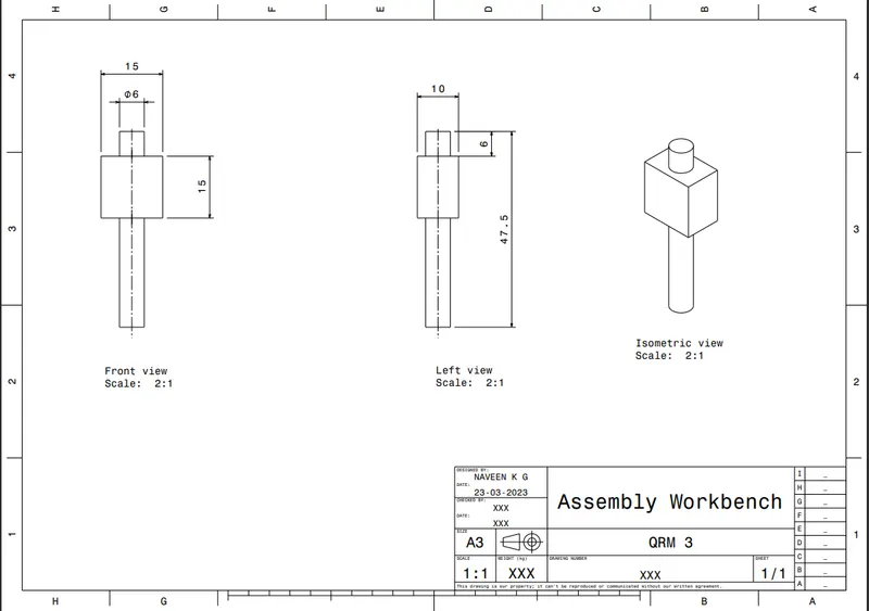
PART 1.4
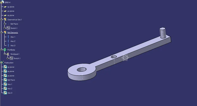
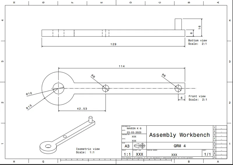
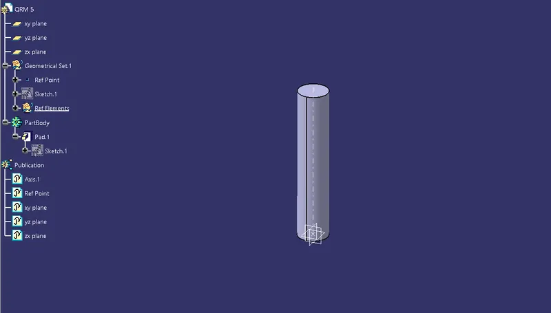
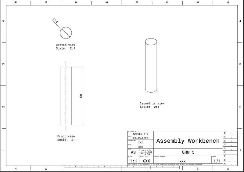
PART 1.5
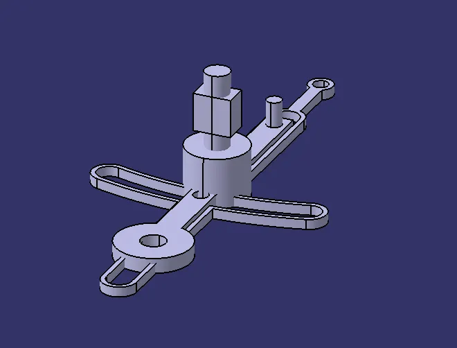
Assembly-1
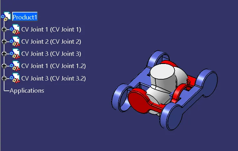
Part-2 (CV joint )
PART 2.1
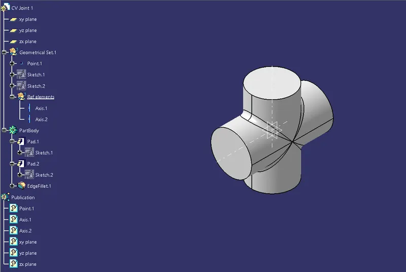
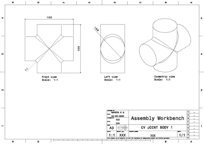
PART 2.2
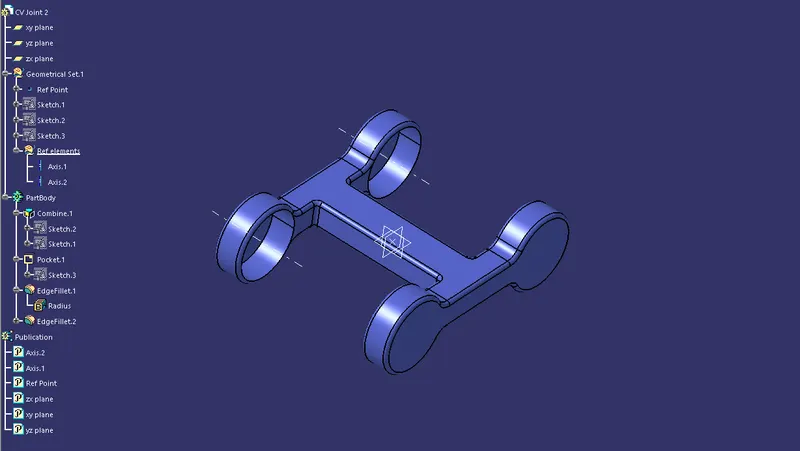
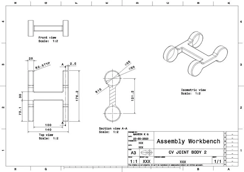
PART 2.3
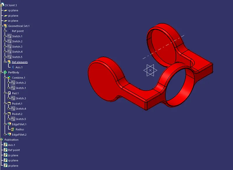
Assembly 2: