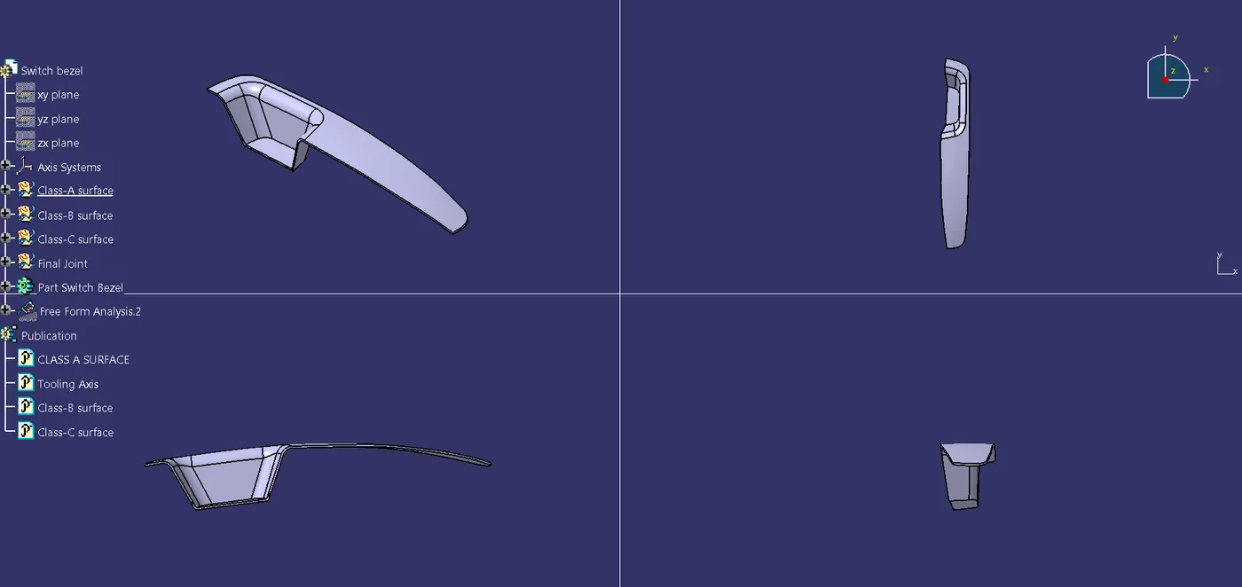
Week 9 - Challenge 2 - Switch Bezel Design
SWITCH BEZEL DESIGN
AIM
To design a switch bezel plastic component from provided Class-A surface.
OBJECTIVE
- To create tooling direction for the design meeting required draft angle.
- To design switch bezel component from Class-A surface by creating Class-B & C surfaces.
- To perform draft analysis on the final model of switch bezel.
DESIGN OF SWITCH BEZEL
TOOLING DIRECTION
- The provided class-A surface is used to generate a tooling axis.
- A new geometrical set is created for tooling axis.
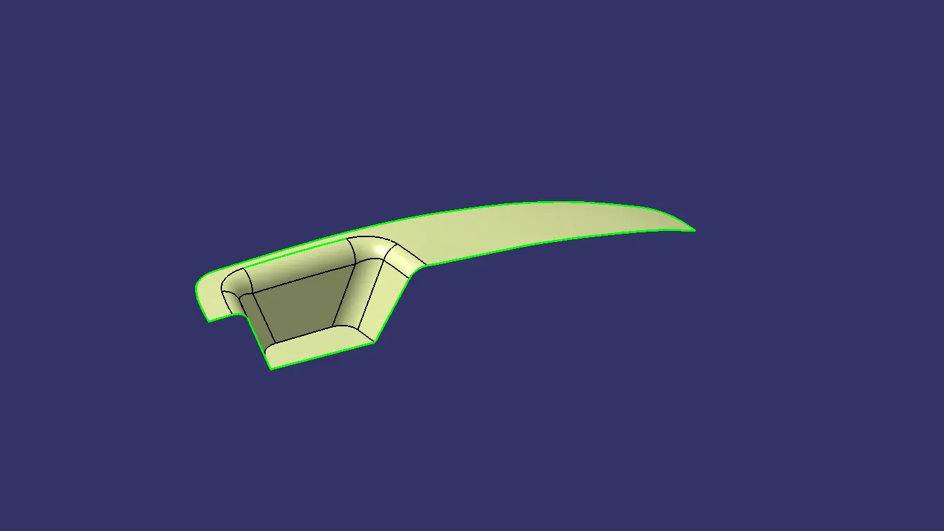
- The bottom face or base is extracted and a center point for the face is marked using a point.
- A new axis system is created about that point.
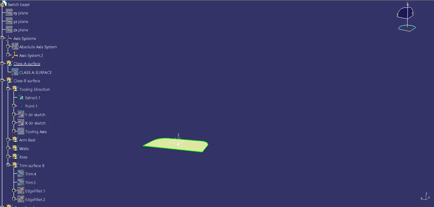
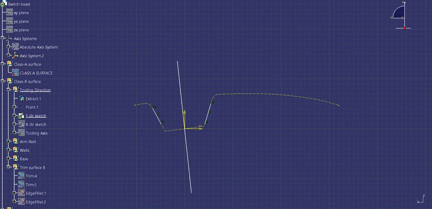
- Based on the new axis system about ZY plane a new sketch is made.
- An intersection is made along that plane with the class-A surface to obtain required reference sketch.
- From this sketch two lines are made in coincidence with the almost parallel lines which forms the walls of the geometry.
- These two lines are bisected with the point at center to create a tooling direction along Y.
- Similarly along the ZX plane another sketch is made.
- An intersection is made along the plane and class-A surface to obtain required reference sketch.
- Only one wall is present in this plane so that reference line is used to create one line.
- Based on the newly created line another line is created at an angle of 6 deg with the point at center as base.
- These two lines are bisected with the center point to create tooling axis along X.
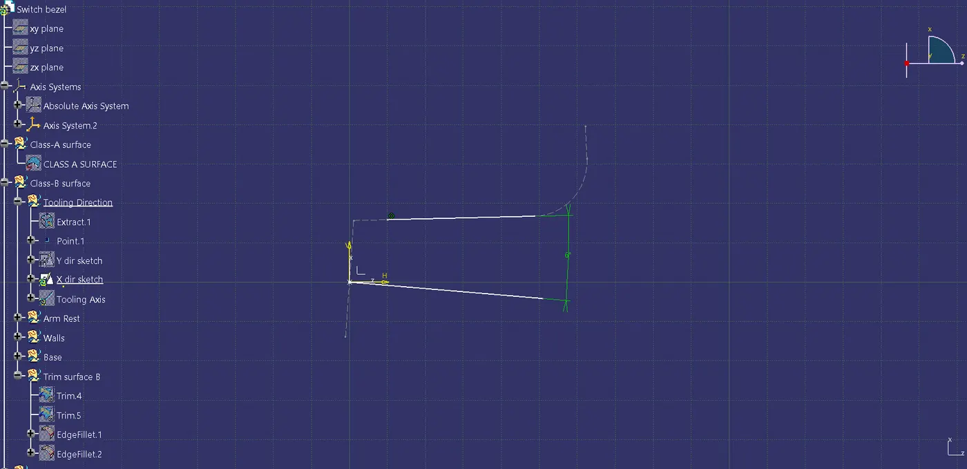
- The two tooling directions (along X & Y) are bisected with the center point to obtain the required final Tooling Axis.
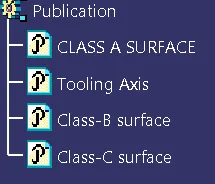
- The tooling axis is published.
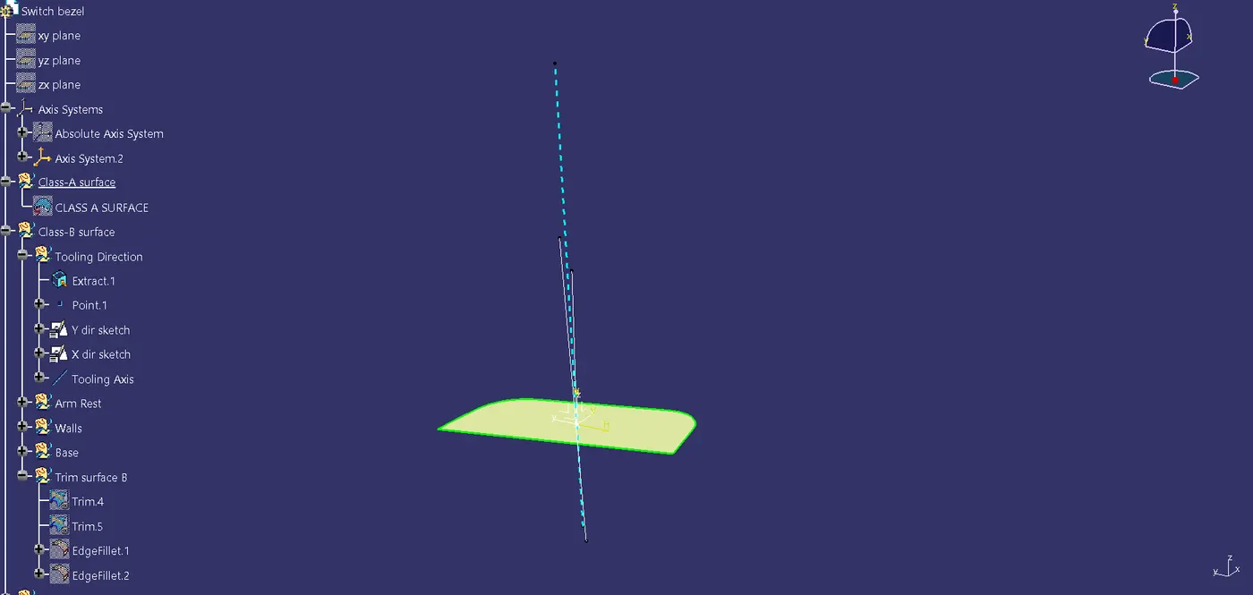
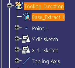
Tree structure for Tooling Direction:
DRAFT ANALYSIS OF CLASS-A SURFACE
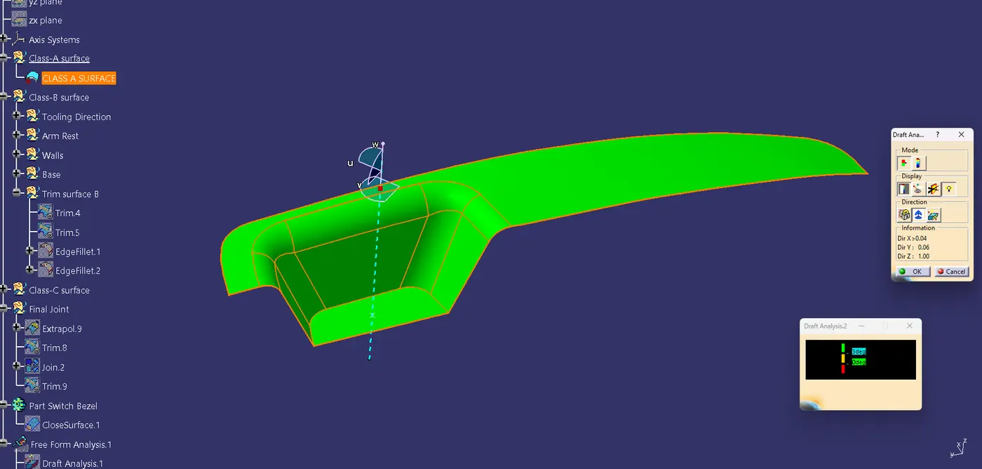
- To verify the created tooling axis the class-A surface is analyzed using feature draft analysis with a minimum draft angle of 3 deg.
- The class-A surface is published.
DESIGN OF CLASS-B SURFACE
Design of arm rest
- New geometrical set named "Arm rest" is created under the set of "Class-B surface".
- The top surface from the class-A surface is extracted.
- The surface is untrimmed to eliminate cutouts.
- The surface is offset to a distance of 2.5 mm (Thickness given).
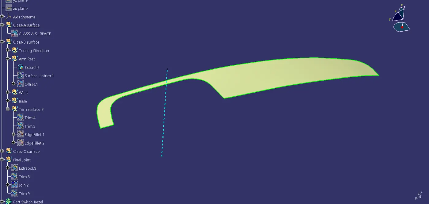
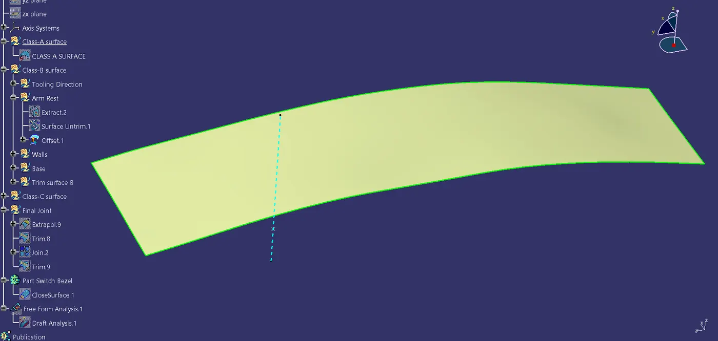
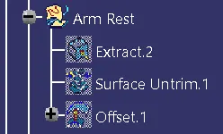
Tree structure for arm rest:
Design of walls
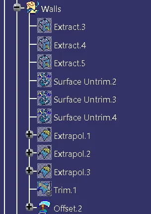
- New geometrical set is created as "walls".
- The three surface of walls from Class-A surface are extracted (excluding fillet).
- They are untrimmed.
- Extrapolated using point continuity by a factor of 70 mm so as they intersect with each other.
- The three surfaces are trimmed in the required orientation.
- The final surface is offset to a distance of 2.5mm.
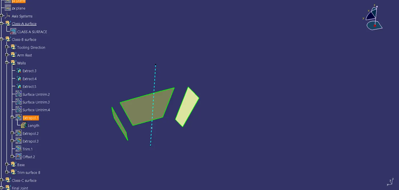
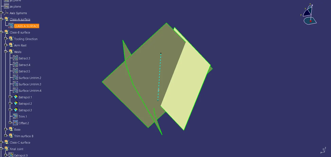
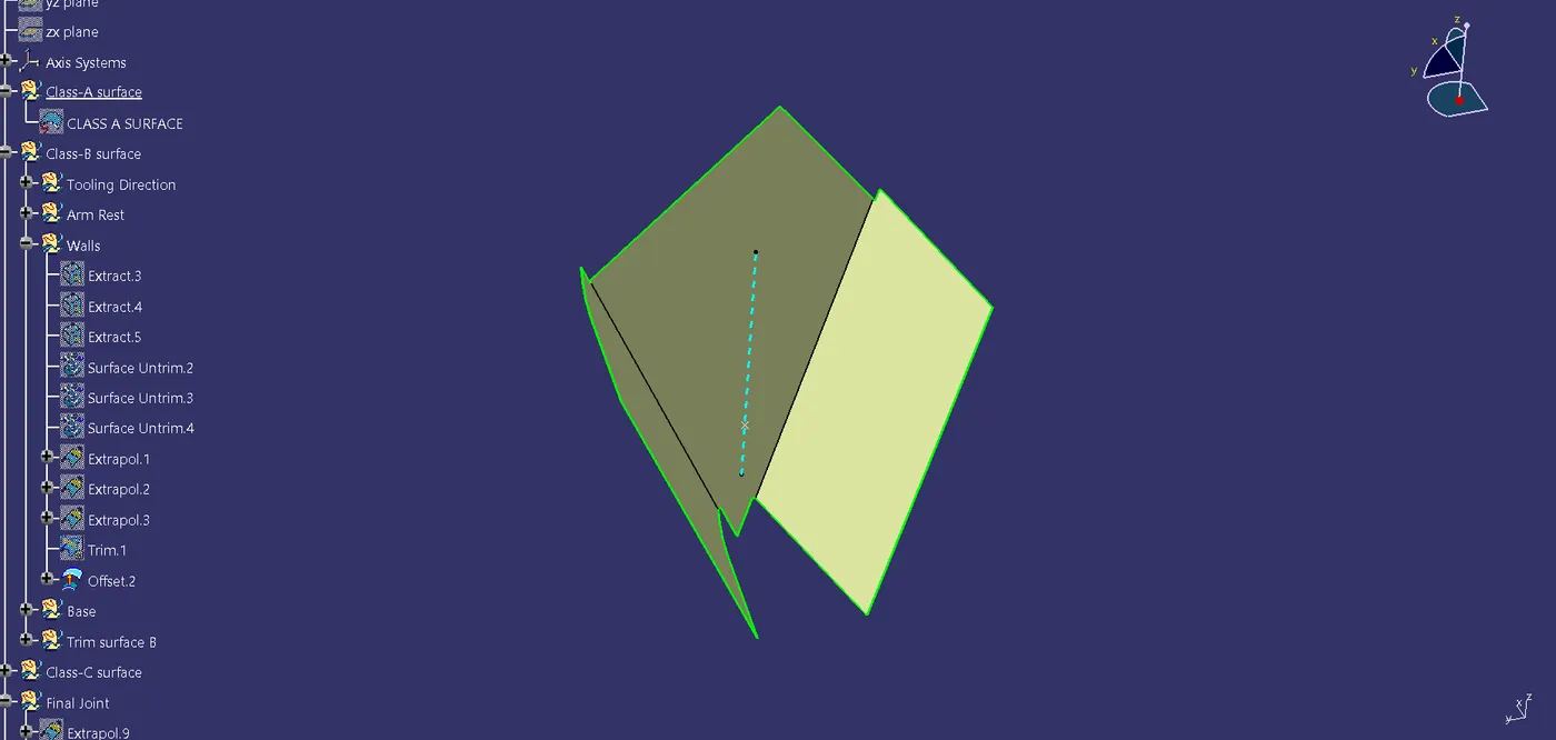
Tree structure for walls:
Design of base
- New geometrical set is created as "Base".
- From the class-A surface the base surface is extracted.
- The surface is untrimmed.
- The surface is extrapolated using point continuity by a factor of 40mm.
- The surface is offset to a distance of 2.5mm.
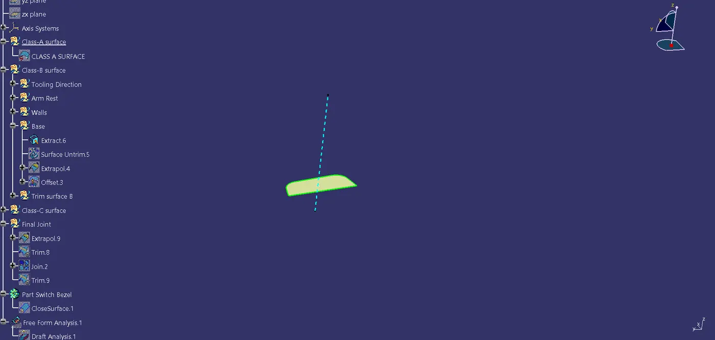
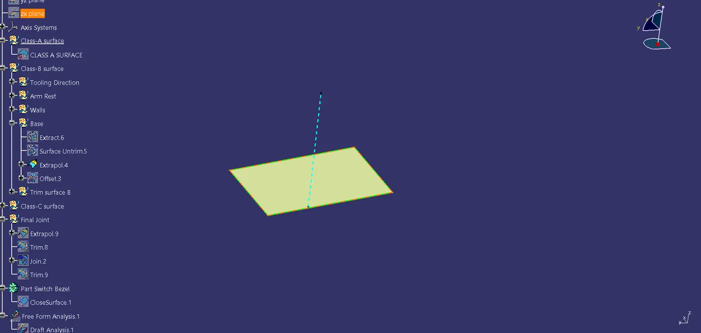
Tree structure of base:
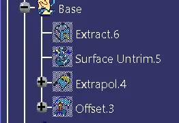
Class-B surface trim with fillets
- New geometrical set is created as "Trim surface B".
- The previously created arm rest surface is trimmed with the walls.
- The created surface is again trimmed with base surface to obtain required final class-B surface.
- Fillets are measured from Class-A surface and found to be 14mm for arm rest edge and 15mm for walls inner edges.
- Edge fillet function is used to provide fillets 11.5mm (14-2.5) for arm rest edge and 12.5mm (15-2.5) for inner wall edges to ensure uniform wall thickness.
- Class B surface is published.
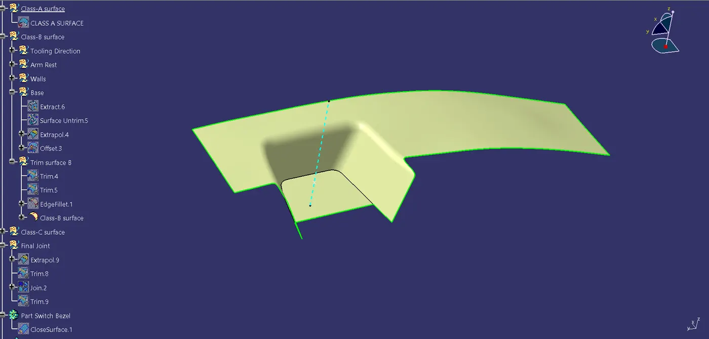
Tree structure for Trim surface B:
DESIGN OF CLASS-C SURFACE
- New geometrical set is created as "Class-C surface".
- From Class-A surface outer boundary is extracted using multiple extract with tangent continuity as propagation type.
- The outer boundary is extracted as two sections, one on the outer edge of the arm rest and other on the inner edge of the arm rest along with edges of walls and the base.
- Curve smooth is applied to provide smooth continuous curve.
- Sweep command is used to generate the surface with boundary as guide curve and tooling direction as draft direction.
- The two surfaces are extracted outwards considering draft so gaps are likely to form along outer edges.
- The required outer edges are extrapolated to intersect with each other.
- The two surfaces are trimmed with each other to get required class-C surface.
- The class-C surface is published.
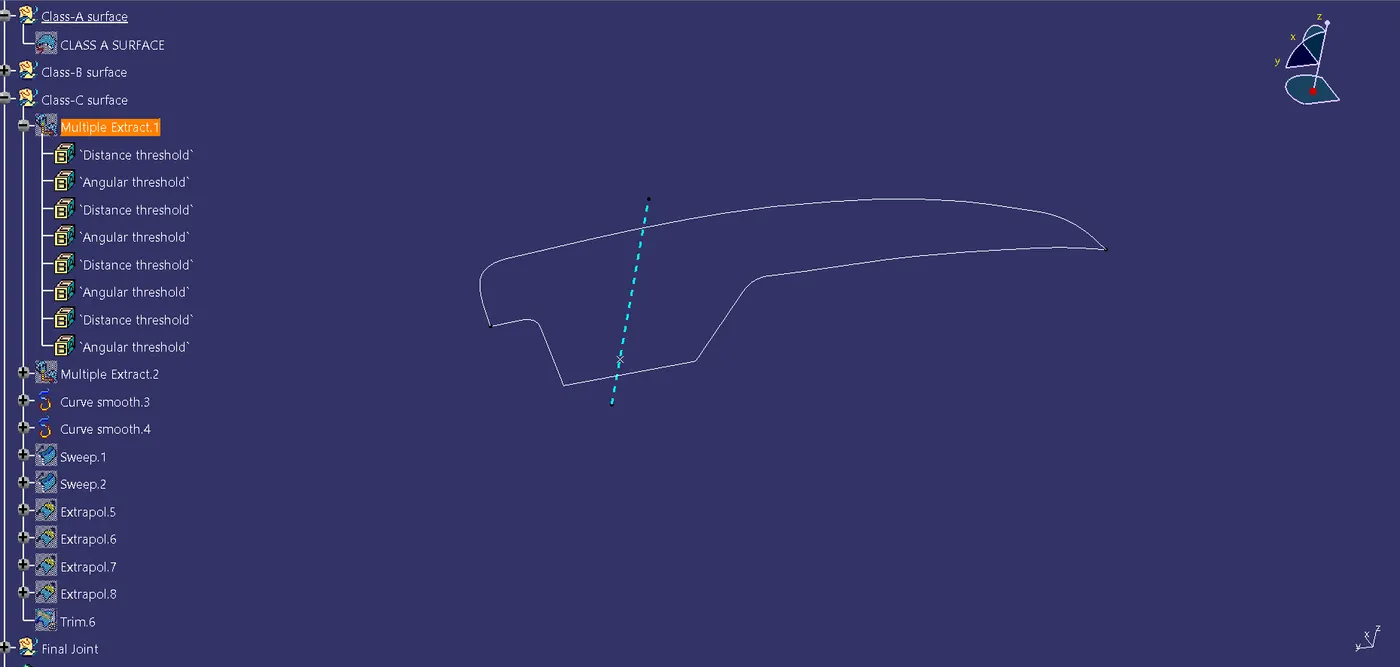
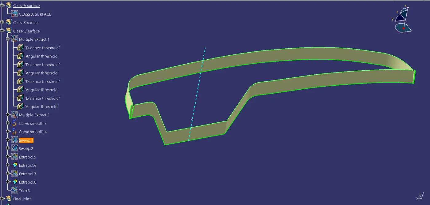
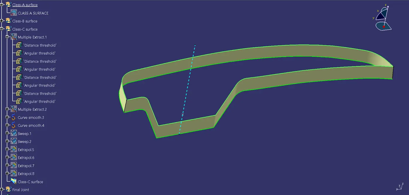
Tree structure for Class-C surface:
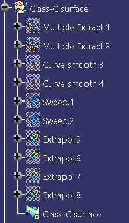
DESIGN OF FINAL SWITCH BEZEL
- New geometrical set is created as "Final joint".
- The three surfaces crated (Class A, B & C) are joined together to create the final closed surface.
- The class A surface is slightly extrapolated (0.05mm),since we used smooth curve operation, to avoid any gaps between the surfaces.
- Class A and C are trimmed and then joined together.
- This merged surface is trimmed with Class-B surface to form the final closed surface.
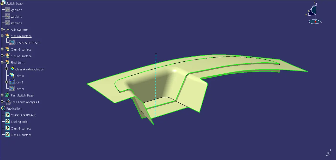
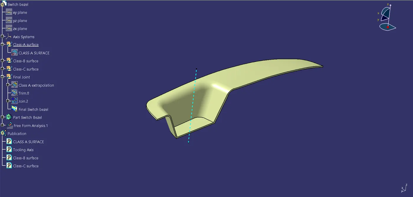
Tree structure for Final Joint:
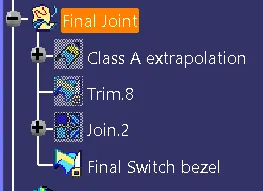
- The final surface is given volume by using close surface command.
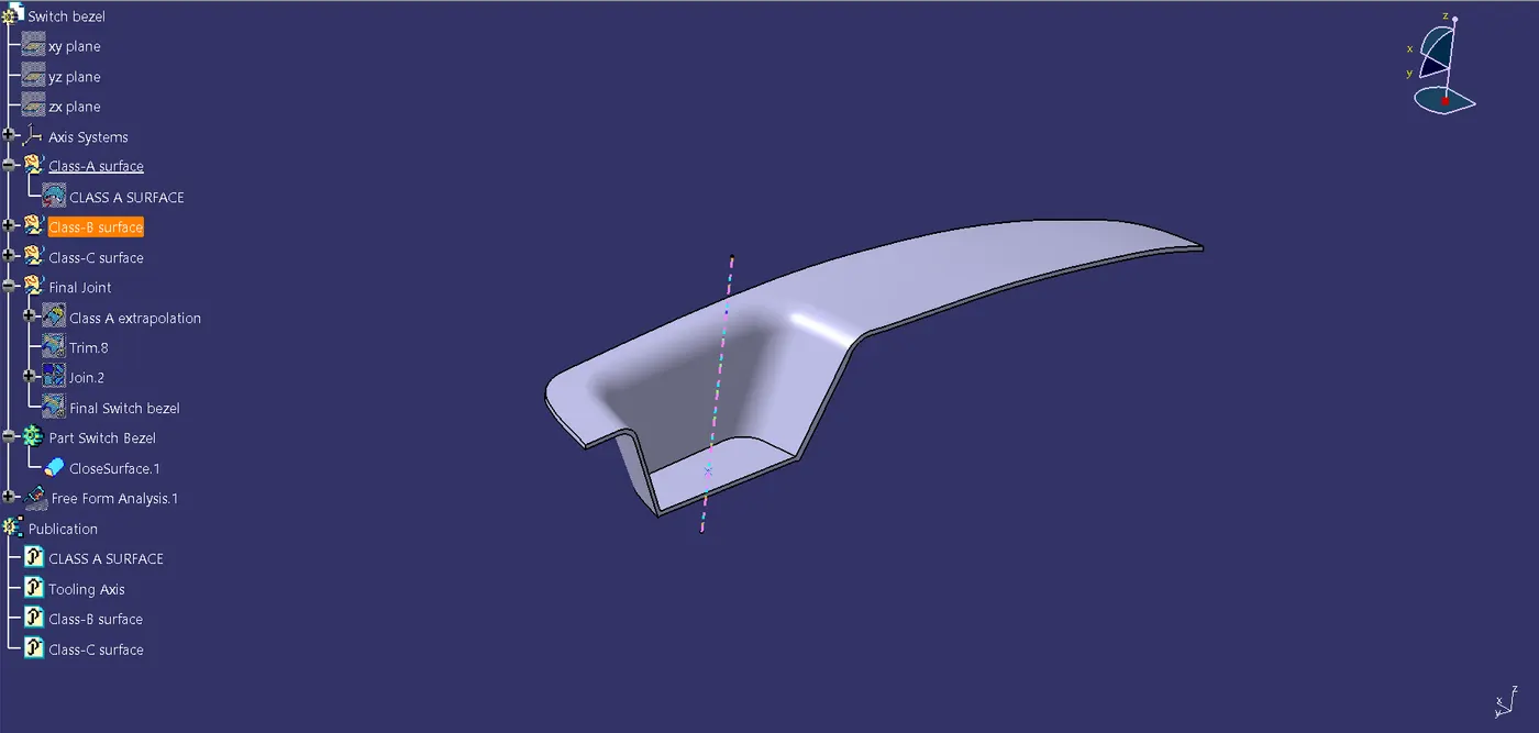
Tree structure for model:

Publications made
DRAFT ANALYSIS OF SWITCH BEZEL COMPONENT
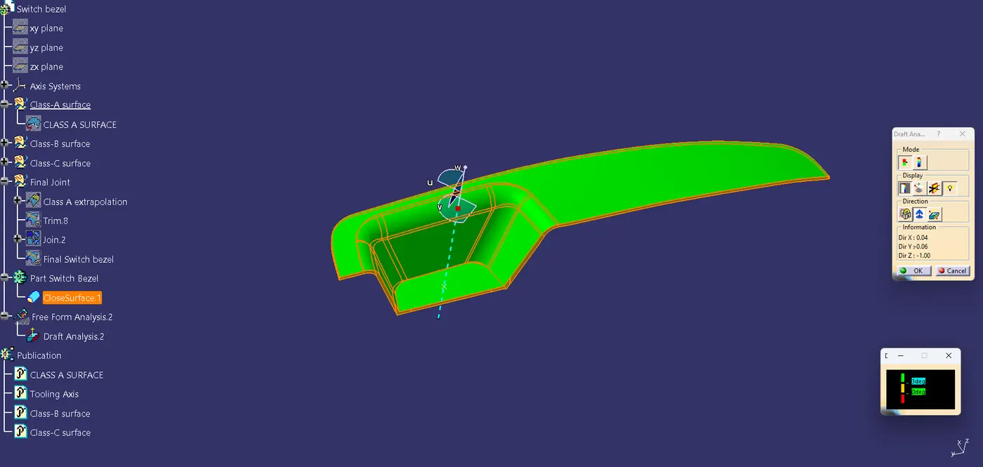
FINAL MODEL