Roof Design
OBJECTIVE
To design a complete assembly of an automobile roof comprising of Front and Rear roof rails, Bow roofs, center roof and Outer panel, with respect to skin data, master sections and taking into consideration of the roof-bow prediction and snow load prediction.
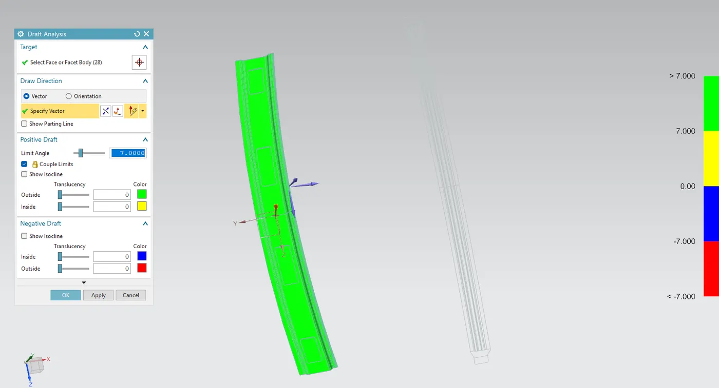
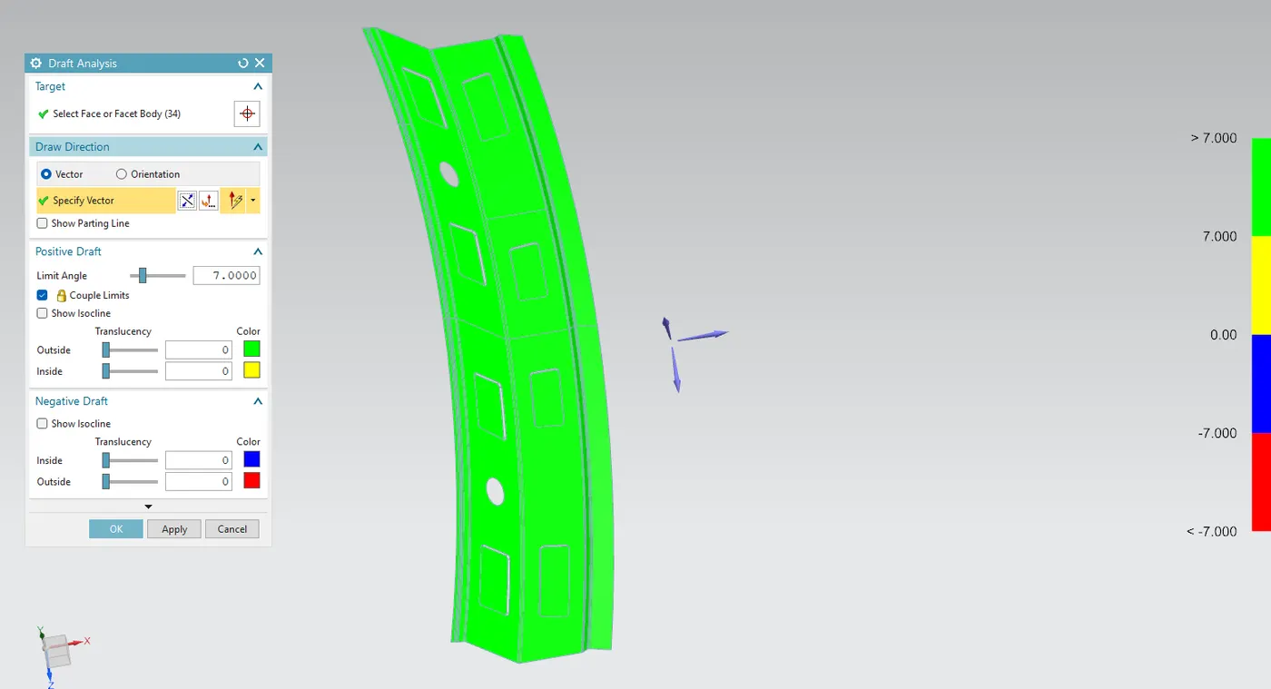
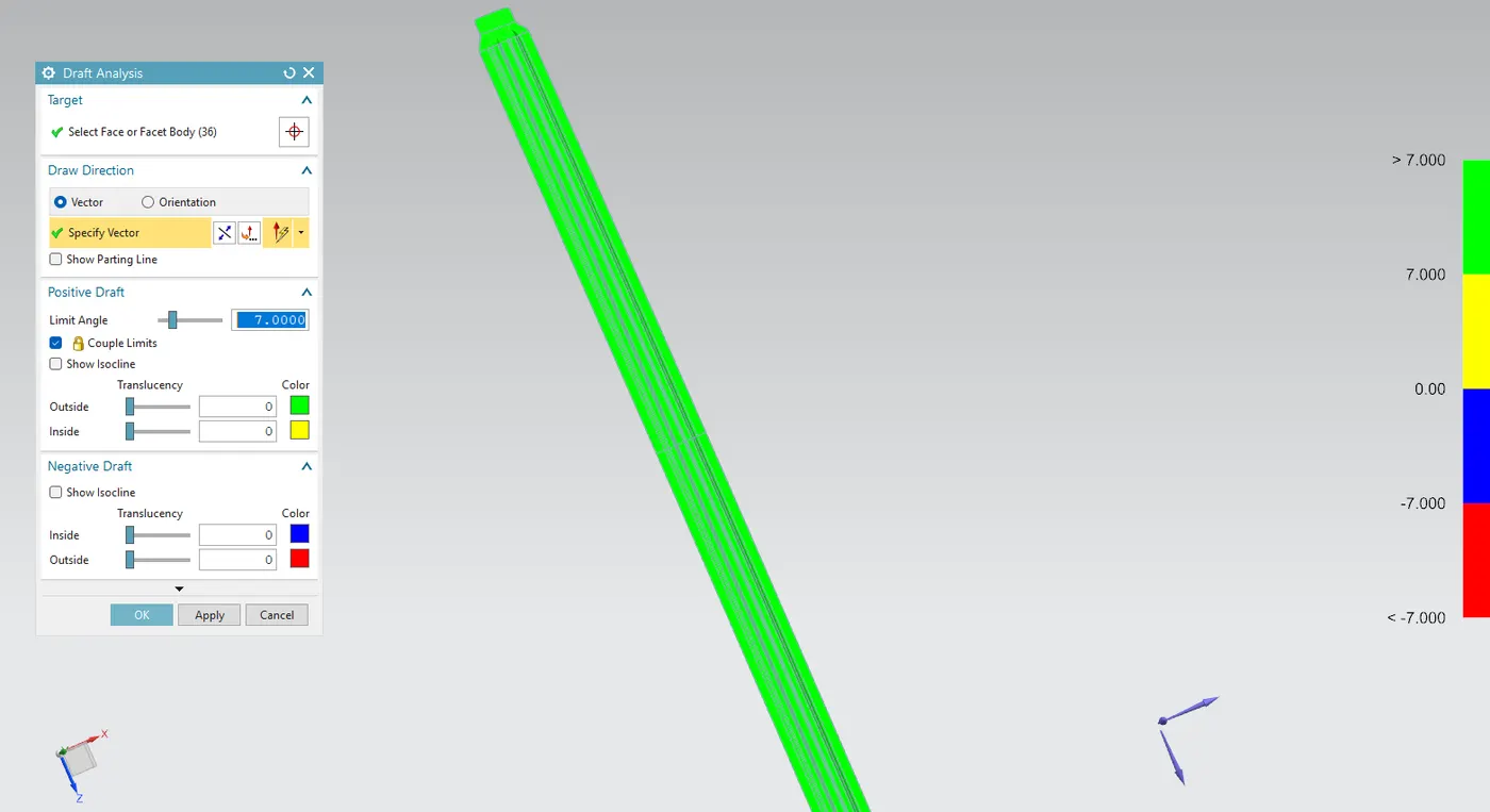
To perform draft analysis on all the components.
INTRODUCTION
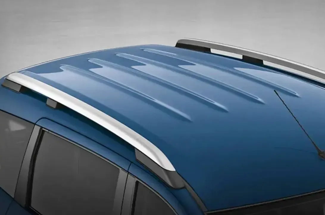
An automobile roof is a part of the outer body that covers the top portion of the vehicle protecting the passengers from various external elements. They provide structural rigidity to the overall design of the car. The roof may sometimes have various accessories like roof racks, antenna or even a sunroof. The front side of the roof connects towards the windshield of the car while the rear connects to the tailgate.
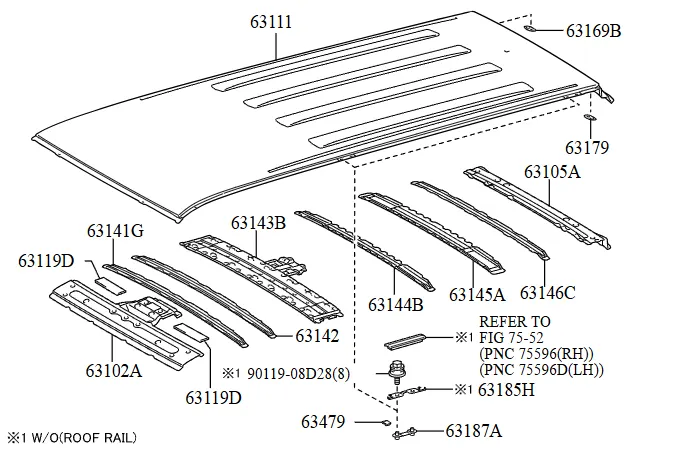
The various components of the roof are:
- Roof outer panel
- Front roof rail - Connects to the windshield, inner panels and body side outer.
- Rear roof rail - Connects to the tailgate and body side outer
- Bow roofs (May have multiple) - To improve load bearing capacity and stiffness.
- Centre reinforcement roof - To reinforce flat area over the roof to sustain loads.
Roof Crush test
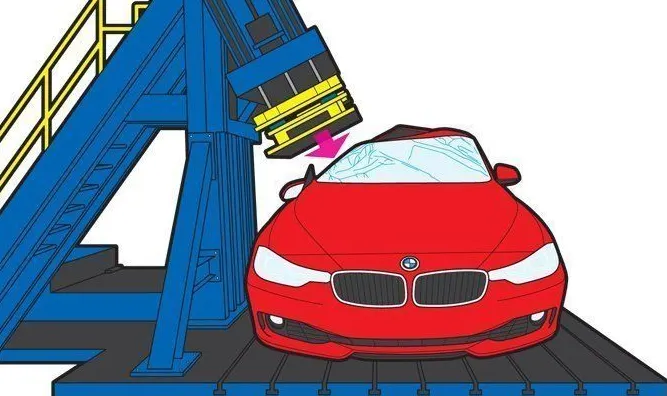
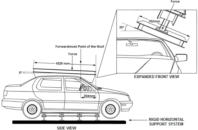
- Roof crush test is a test introduced by the Insurance Institute of Highway Safety or IIHS. The test involves pushing an angled metal plate on one side of the roof at slow and constant rate while the vehicle is fixed on horizontal surface with all doors locked and windows closed.
- The significance of the test is that a more stronger roof can enhance the survival chances of occupants during a rollover, decreasing likelihood of injuries from roof being crumbled or shattering windows.
- If the displacements are going over the required values it indicates a lack in strength and the overall strength of the roof needs to be increased. It can be achieved by increasing thickness of roof or by increasing thickness of bow roof thickness or increased number of mastic points etc.
Design of Roof in NX CAD
Design of Outer Panel
After obtaining the skin data for the roof the outer panel can be designed with help of master sections for front as well as rear roof rails.
Given below is the provided skin data: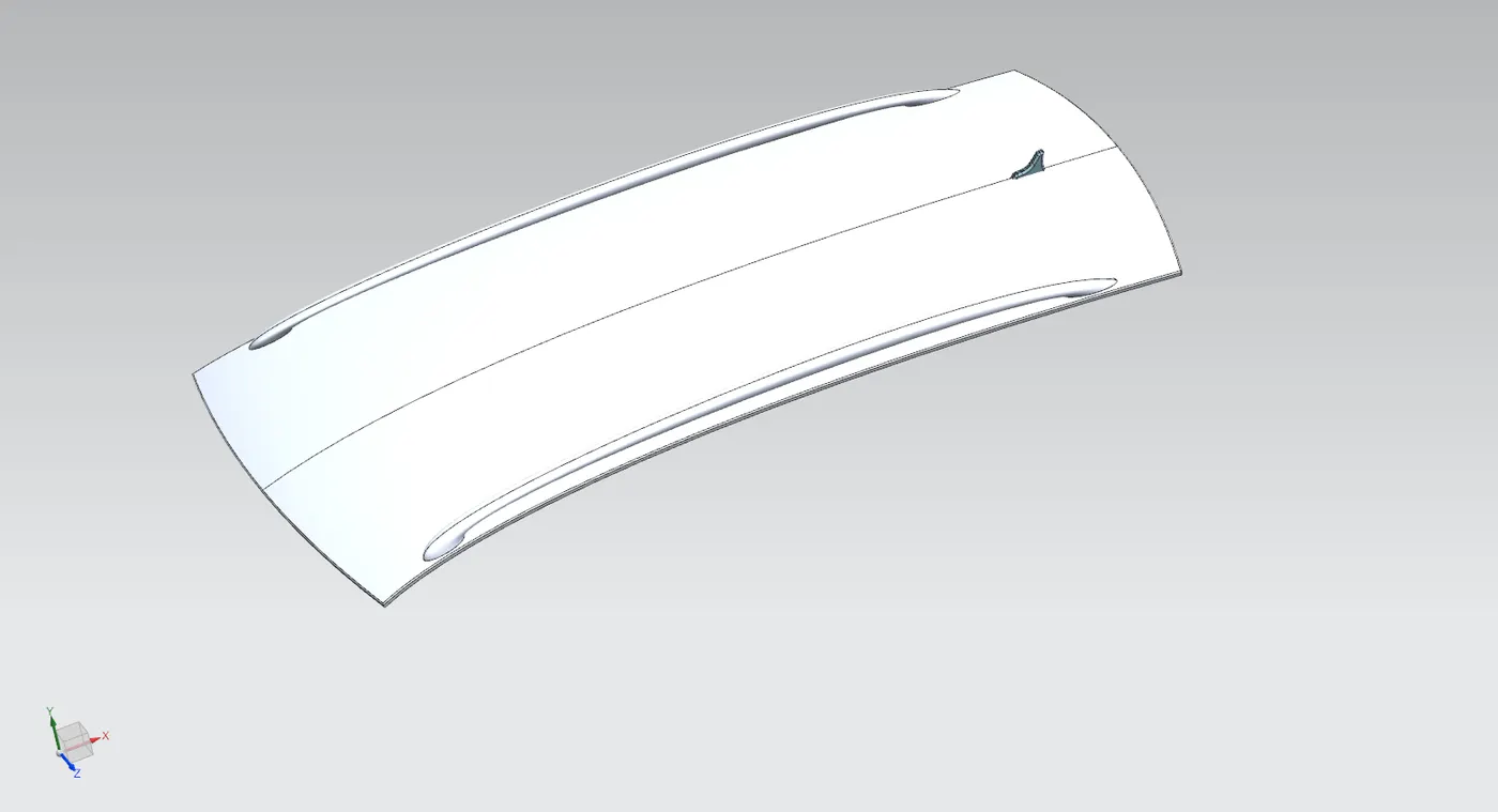
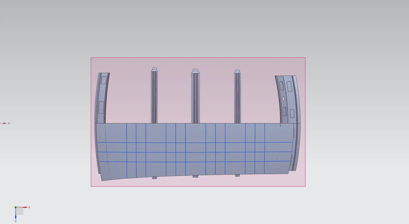
Now using this skin data the surface is extracted and all other components are hidden, since the roof is symmetrical we use half of the side to produce all the necessary components and later mirror them accordingly.
After extraction the surface has holes from the roof rack mount. "Untrim" command is used to remove this and get the sheet metal surface and the ends are smoothened out to round corners using "Bridge curve" command as follows:
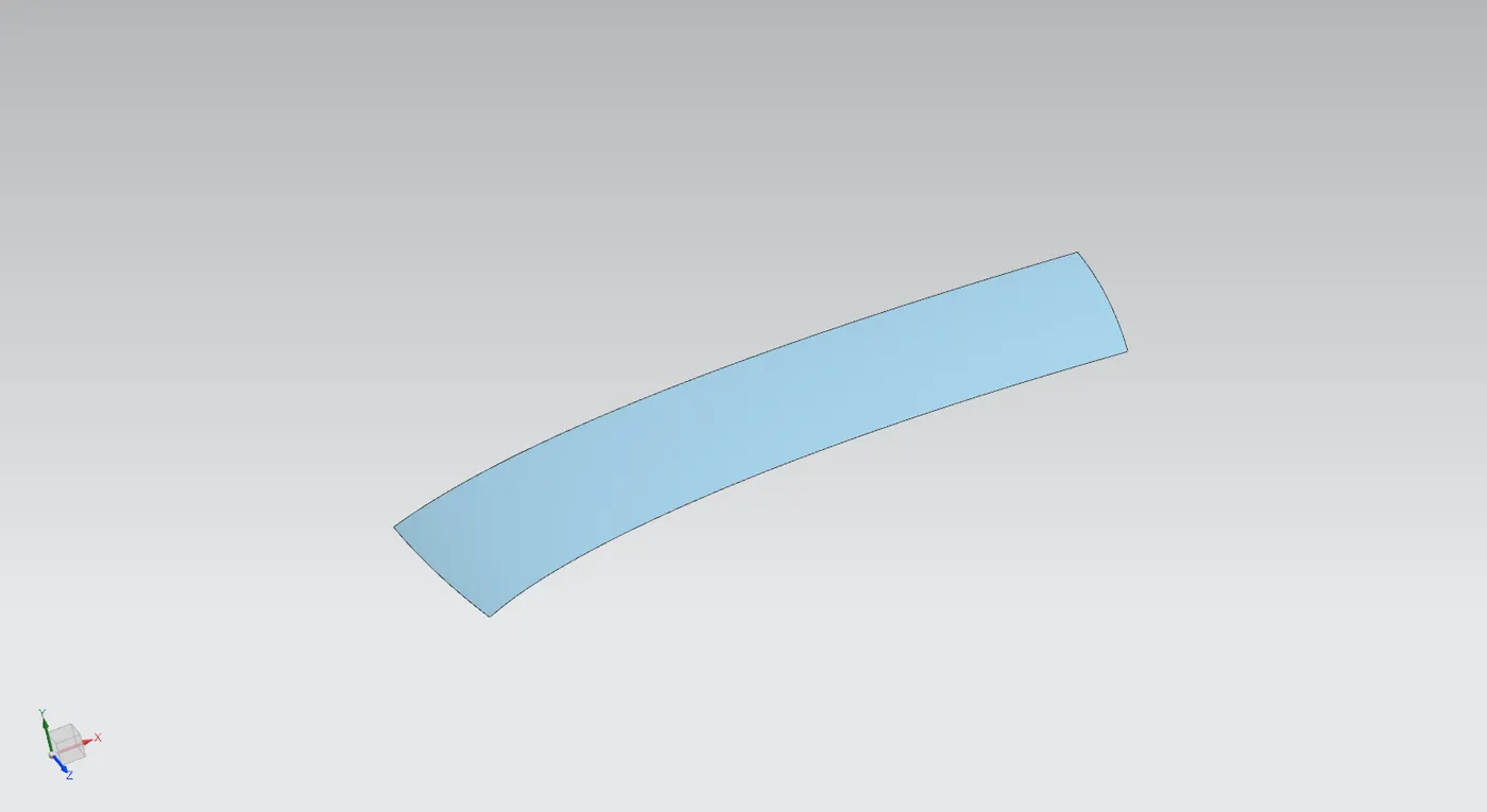
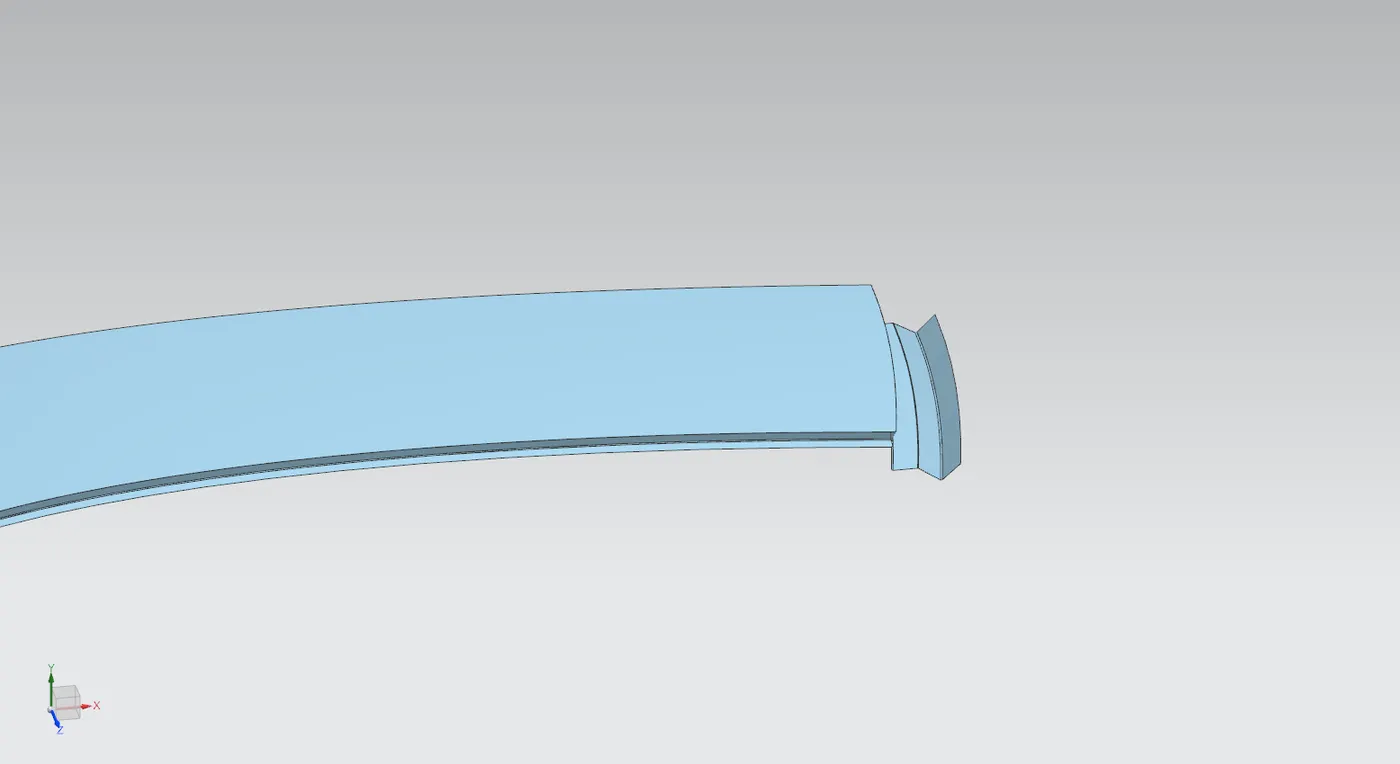
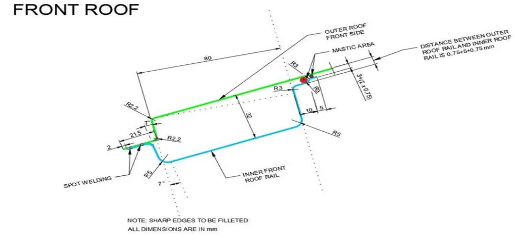
Now considering the Master section for the front roof rail, "Law extension" command is used to extend the sheet with an angle of 7 degree and 15 mm, which is further extended to a length of 21.5mm. Similarly the sides are also extended.
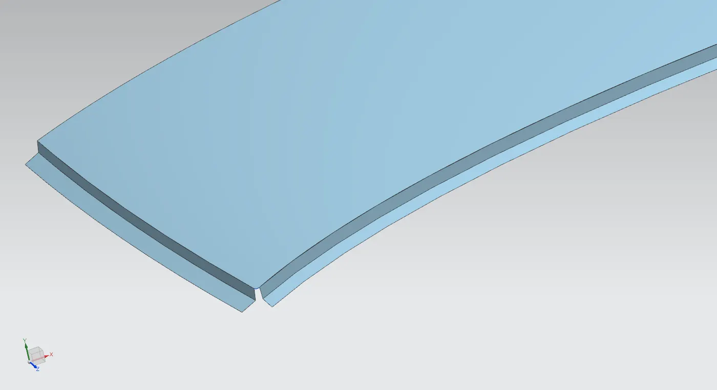
Face blending is used to provide blends of radius 2.2mm as in the master section. A bridge curve command is used to create a guide along the extended surfaces.
Using "Studio surface" command these edges are converted to a single curved surface.
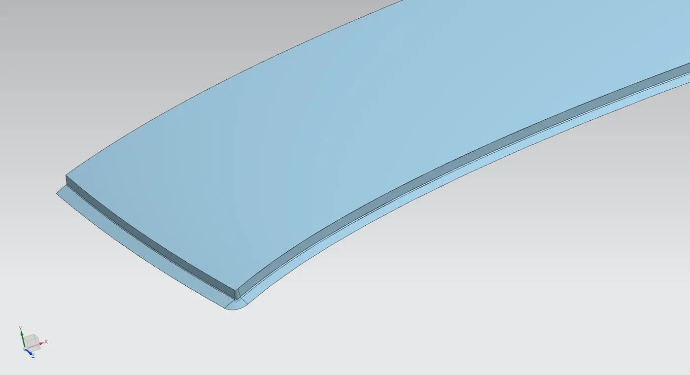
Using a similar method for the rear with reference to the rear roof rail master section, the surfaces are extended, edges are blended and corners removed to obtain the rear side of the outer panel as below:
Design of Front Roof Rail
Front roof rail is created with help of previously designed outer panel and master section for front roof rail.
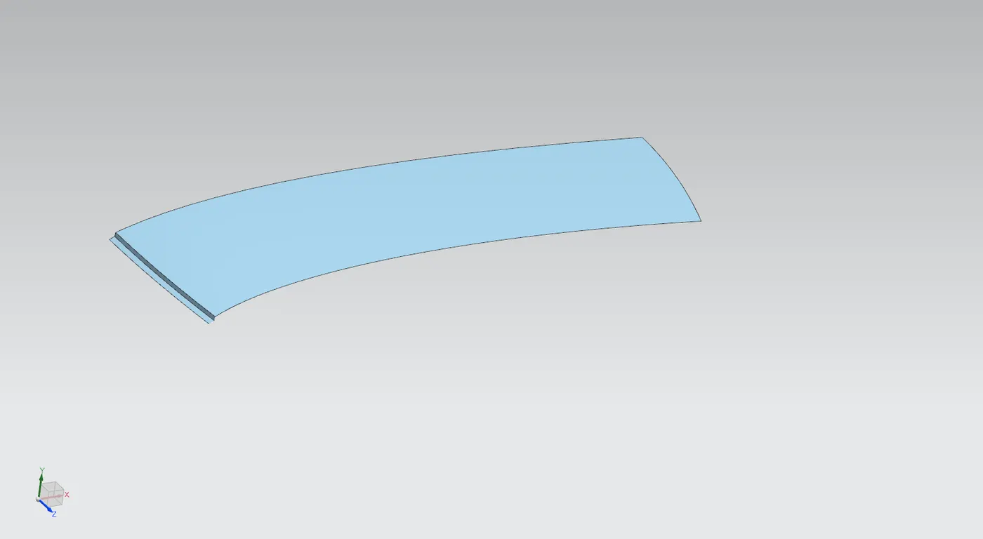
To begin we create a new part inside assembly as Roof rail front and extract the top surface and ditch area created in outer panel using "wave geometry linker".
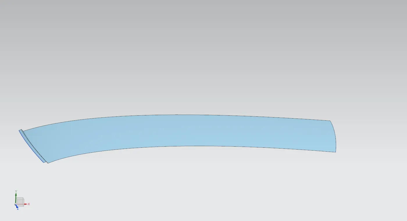
- Top surface is offset downward 32mm to create the first surface for the roof rail. From here a law extension is used to extend a surface upwards at 45 deg corresponding to the generated surface.
- The flange is created at an offset of 1.7 mm from outer panel's flange (considering .2+.75+.75).
- A new datum plane is created at the edge of the outer panel with orientation with XC co-ordinate and at a distance of 80mm (from master section).
- This datum plane is used to create offset curves on the surface with same profile as the surface on outer panel. This is done at varying distances according to the master section (80mm, 10mm from last curve, 5mm from last curve)
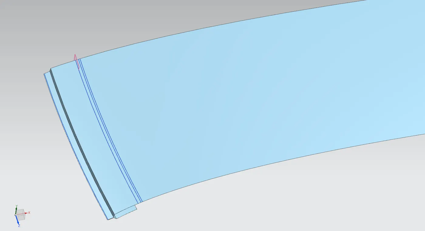
- 2 separate offsets are made for 2 different flanges, these are then trimmed using the same curves as before accordingly.
- The flanges are joined together using studio surface.
- These parts are sewed together to form a single sheet. This sheet is given edge blends at the edges using dimensions from the master sheet.
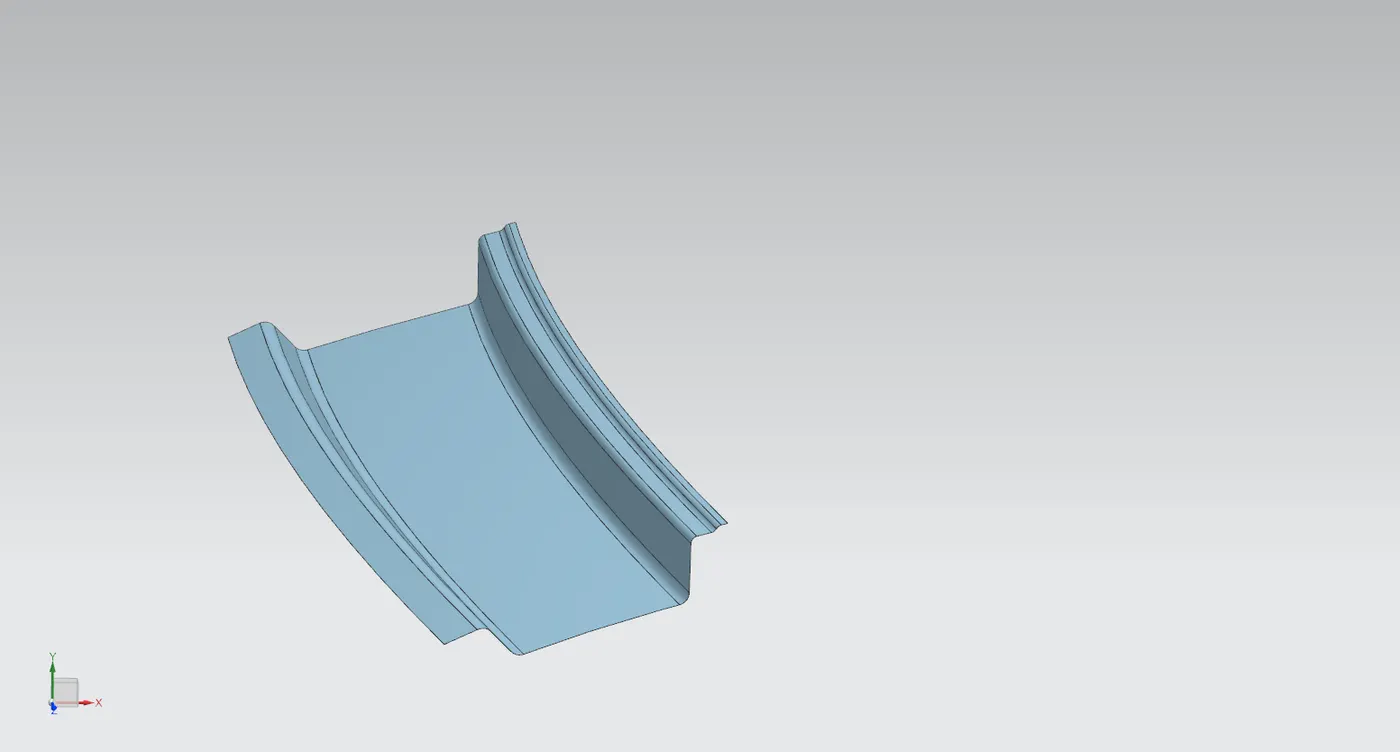
- Sketches are made and are projected to the surface for making embosses.
- The outermost edges are trimmed off, as the roof rail is slightly shorter in span than the actual roof to accommodate more components coming from the side.
- The centre part is extended little and trimmed off at exact centre.
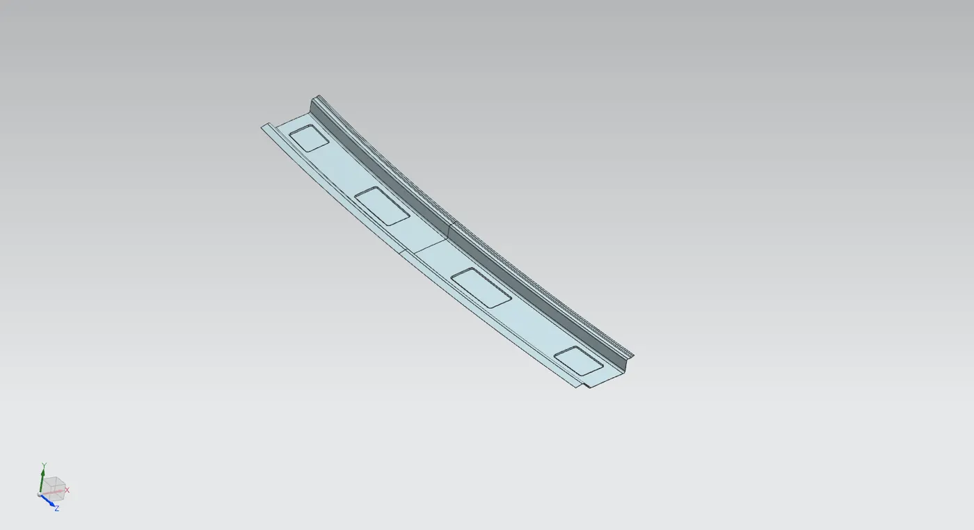
- The whole geometry is mirrored about the cent to create a complete front roof rail.
- The two parts are joined together using sew command.
- Thickness of .75mm is added in the upward direction using thicken command.
Design of Rear Roof Rail
Rear roof rail is designed using previously created outer panel and Rear roof rail master section.
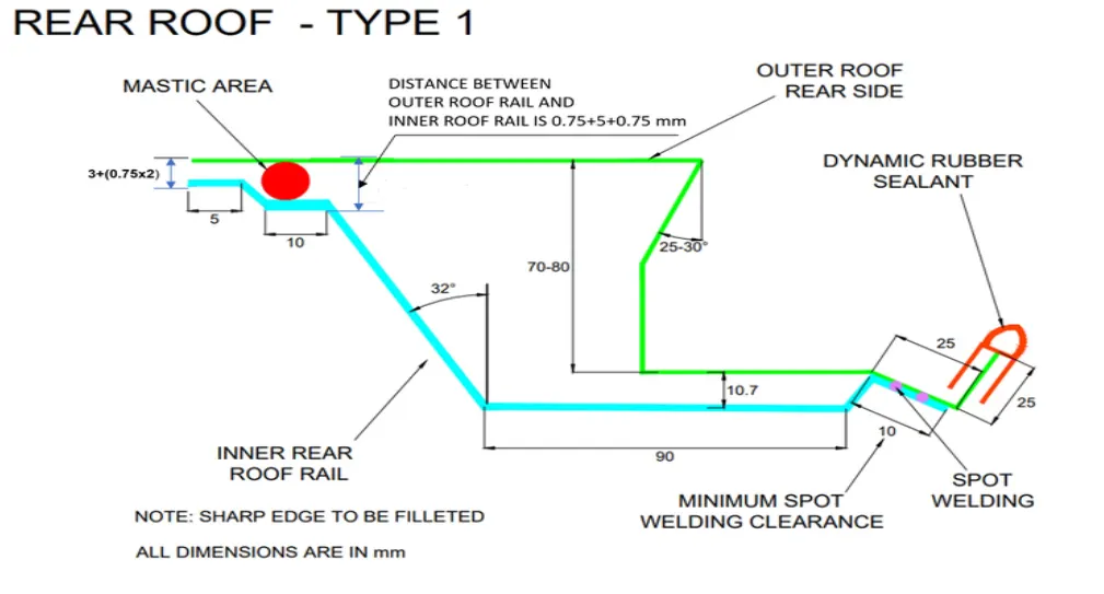
To begin we create a new part inside assembly as Roof rail rear and extract the surface required using wave geometry linker.
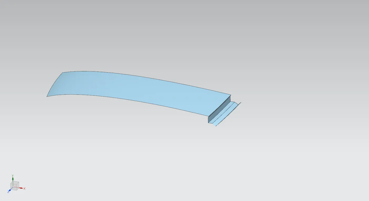
- To create rear roof rail we follow a similar approach as the front roof rail. The flange from the outer panel is offset to a distance of 1.7mm (considering thickness and spot welding).
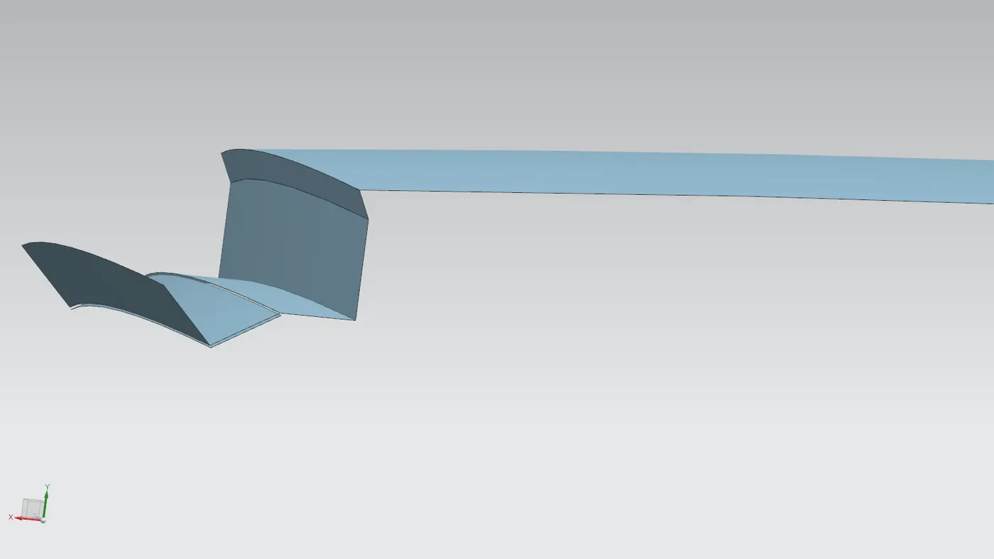
- The final 2 flanges are made by offsetting the surface to 6.5mm and 4.5mm each and using law extension at 32 deg to intersect with each other and making corners using trim and extend command.
- These are then combined using sew operation.
- The edges are given blends to avoid sharp edges (3mm each).
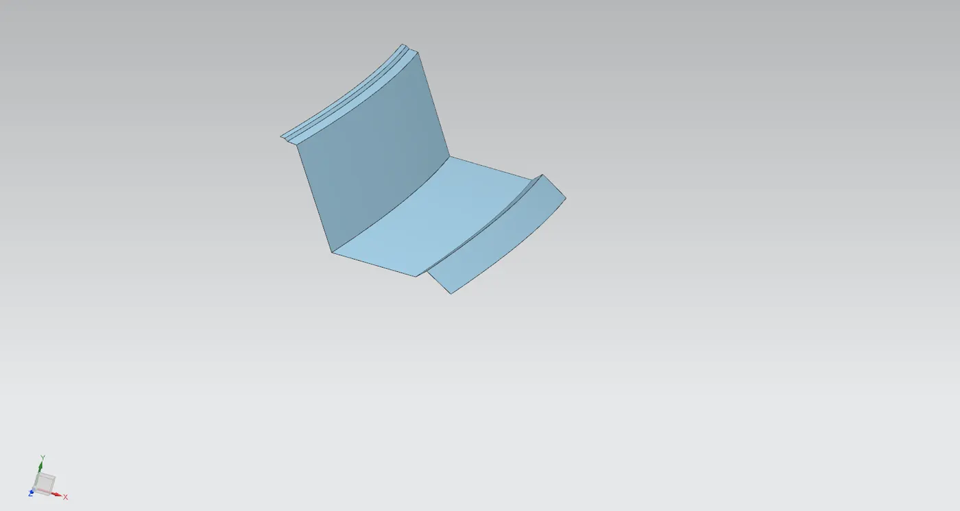
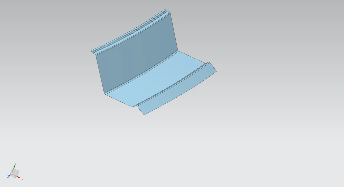
- Two datum planes are made inferred from the larger surfaces to create sketches for the embosses.
- The curves are drawn over the datum plane and projected onto the surface and are made to emboss, along with required holes.
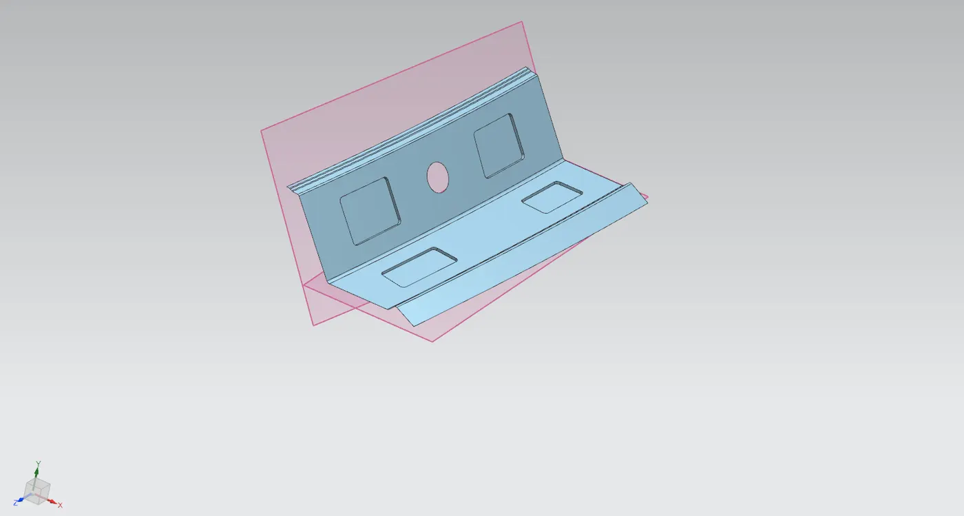
- The whole geometry is given an extension towards the centre and trimmed along the centre through XY plane.
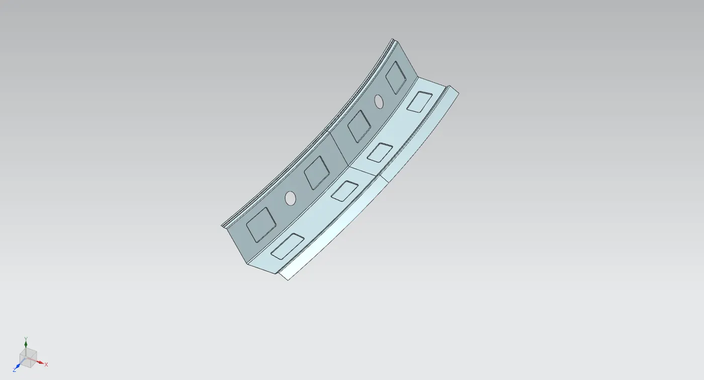
- The geometry is mirrored and attached using sew.
- The component is given thickness of 0.75mm using thicken command.
Design of Bow roofs
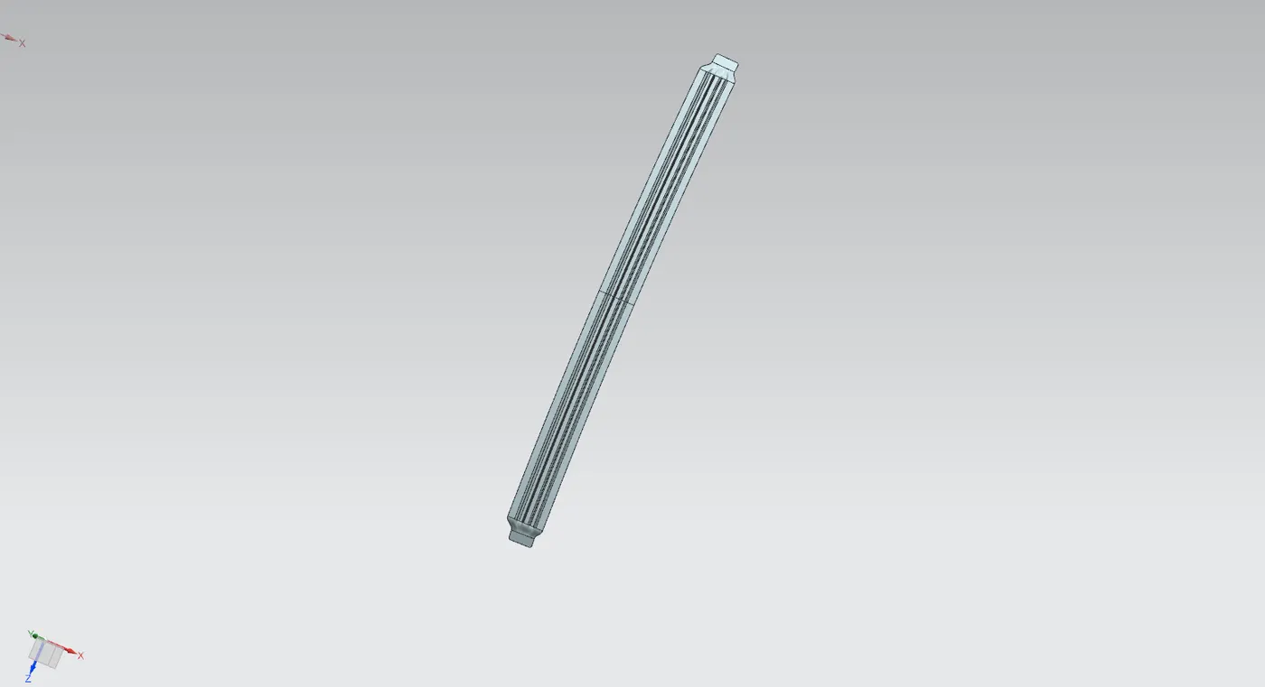
For this design there are two bow roofs, they are designed using the master section and the outer panel as reference.
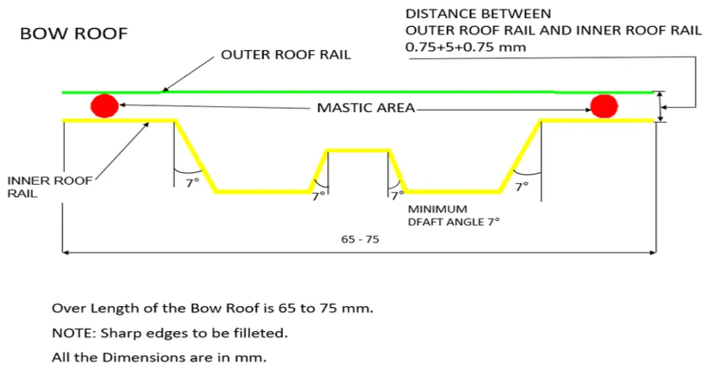
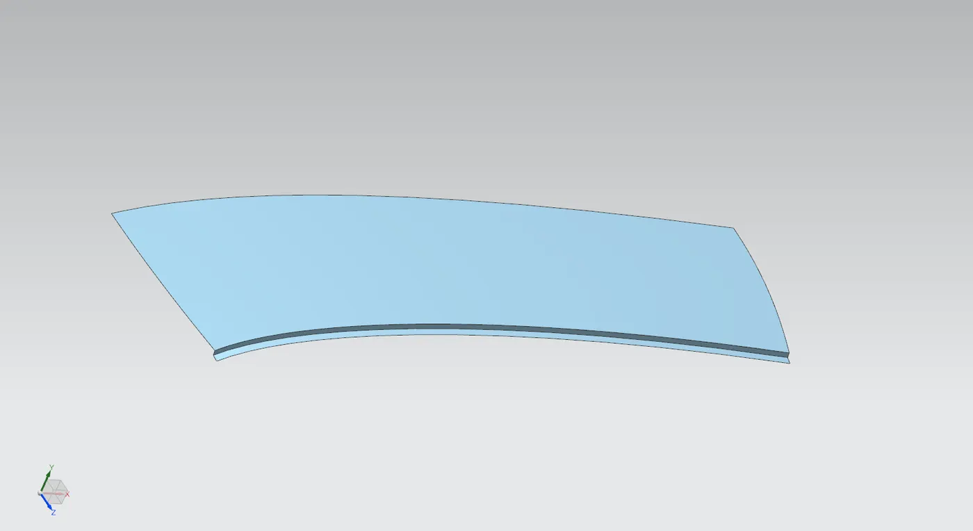
- To create the flanges for the bow roof, a new datum plane is obtained and placed at 28% from the front of the roof. From here the sections are developed towards the rear, an intersection curve is made to obtain the first curve.
- From this curve other sections are offset for the flanges. The overall width of the bow roof comes to 66mm (between 65-75mm). The sections are offset as 15mm >> 12mm>> 12mm>> 12mm>> 15mm.
- Three set of flanges are made by offsetting the outer panel surface to 3 different points (6.5mm, 3mm from last flange and 5mm from previous flange).
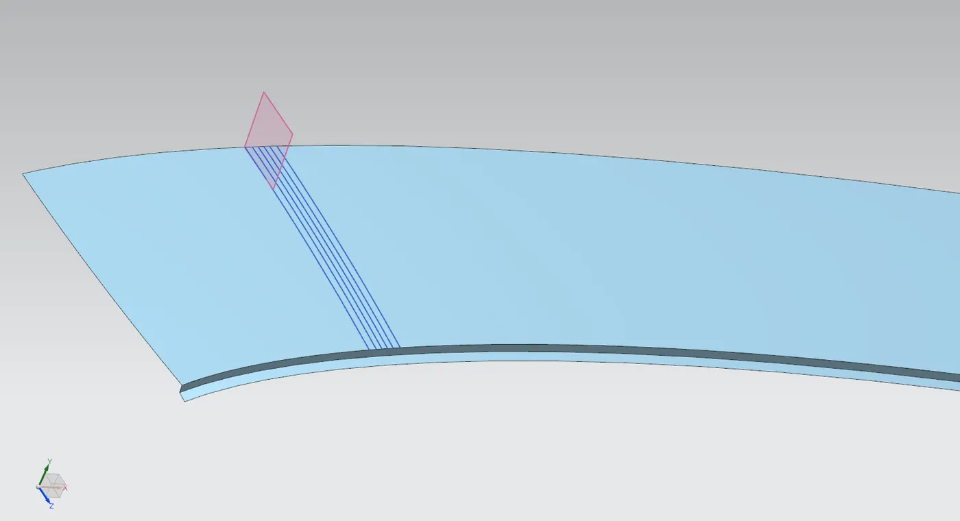
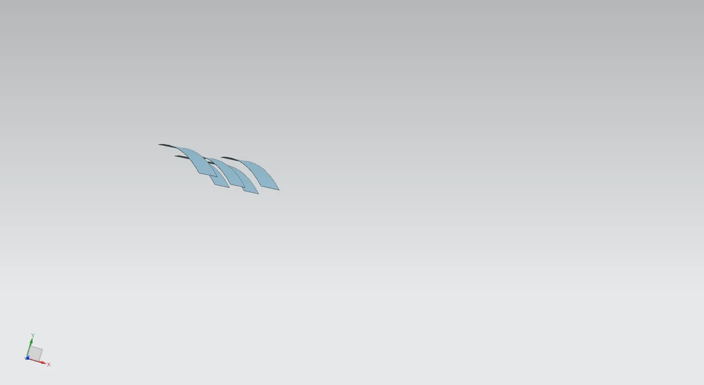
- Law extension command is used to join the flanges together, angle of 7deg is given as in the master section.
- These parts are joined by using sew.
- Edge blends are given to remove sharp edges from the sheet.
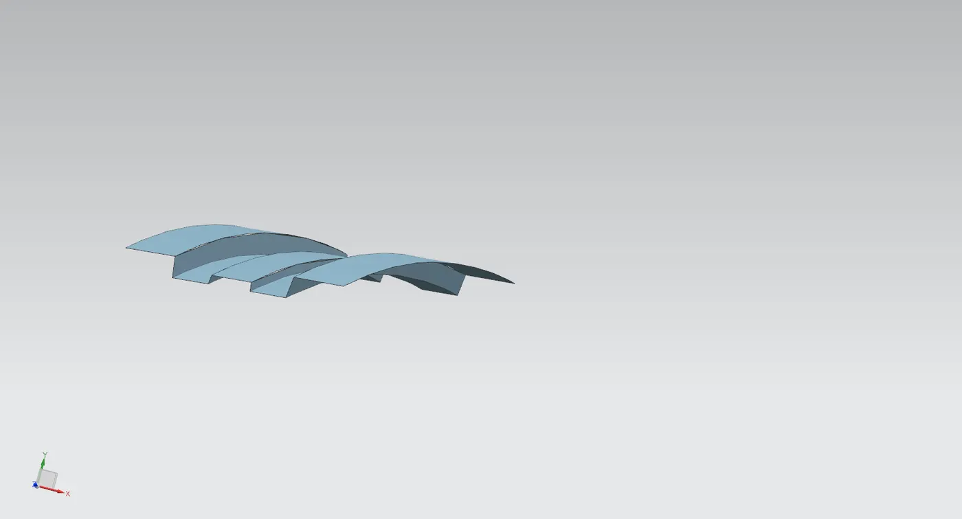
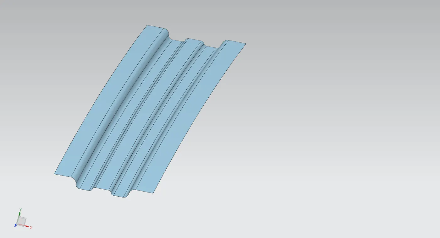
- A small section from ditch region is selected for joining with the bow roof, the bow roof section is slightly trimmed towards the inside beforehand. The small section is obtained by offsetting the outer surface to a distance of (.75+.75+.2mm) in downwards direction.
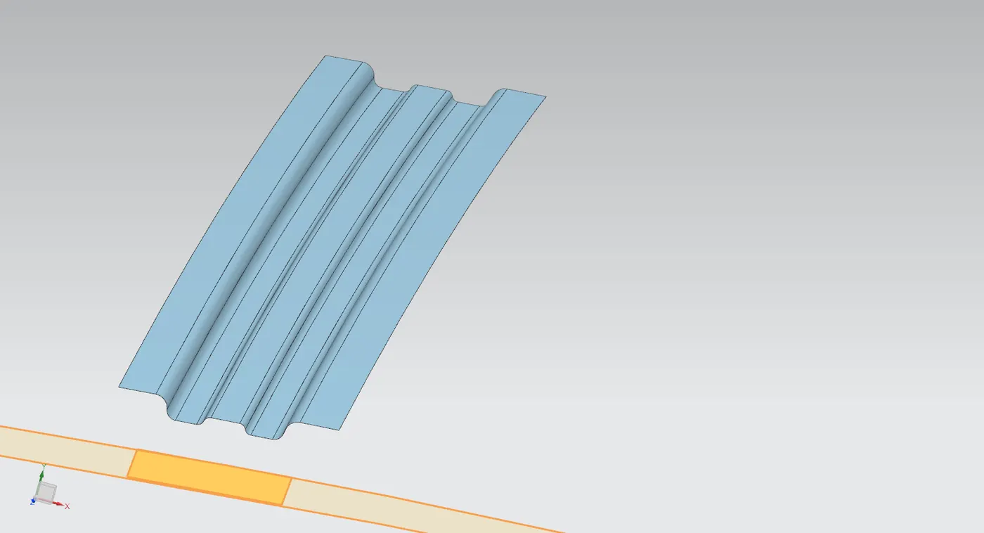
- Bridge curve command is used to join the two sheets together.
- The new surface between them is made using through curve mesh command by using the edges of the surfaces as primary curves and the bridge curves are guides.
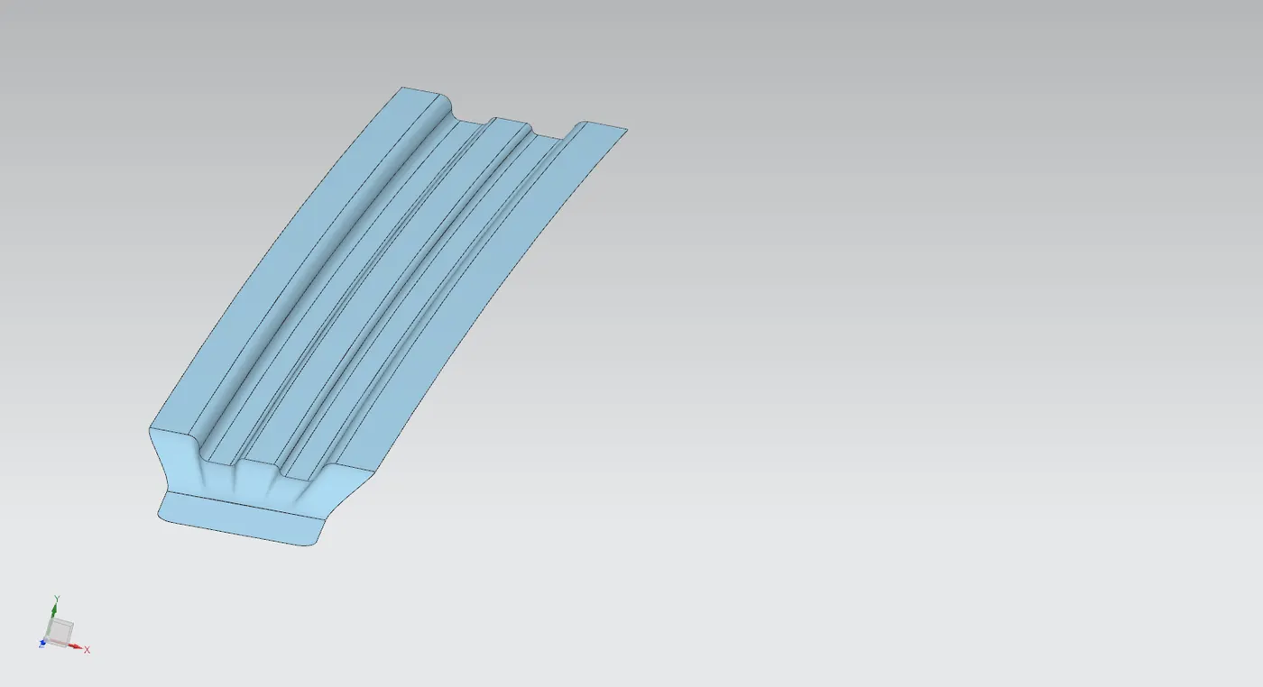
- These surfaces are joined together using sew command.
- The geometry is mirrored along the XY plane and again joined together.
- Thickness of 0.75mm is applied using thicken command.
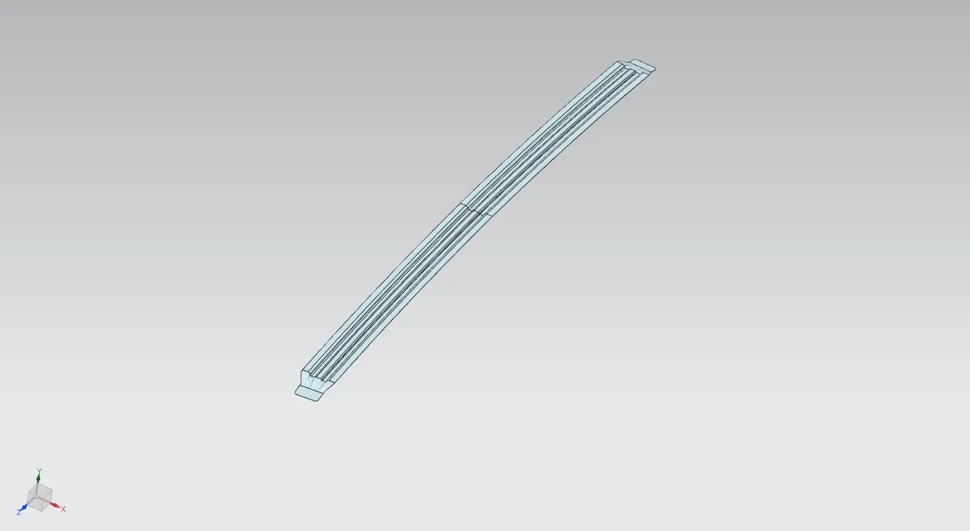
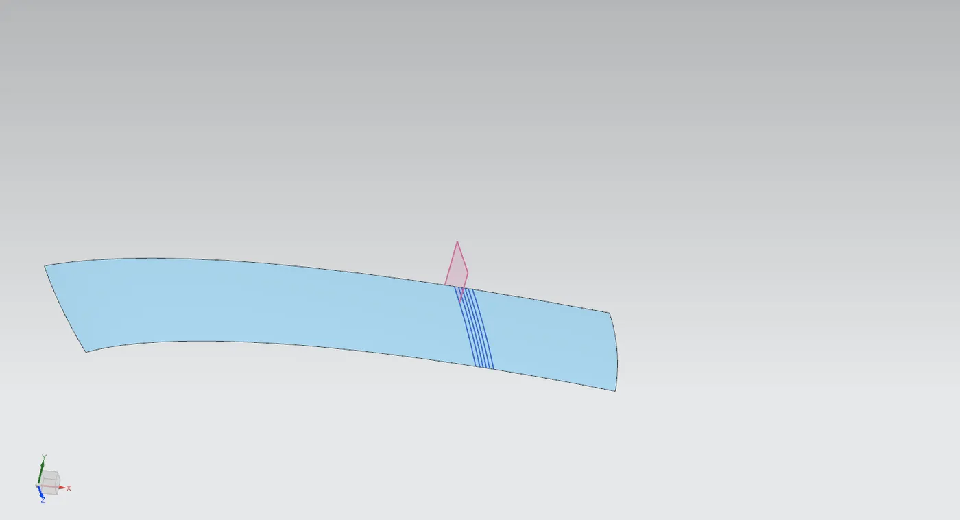
- Bow roof 2 is made in a similar approach but with slight changes to initial steps to offset the start towards the rear by making a datum plane at 70% arc length from the curve on the outer panel.
- All other operations are carried out as same as Bow roof 1.
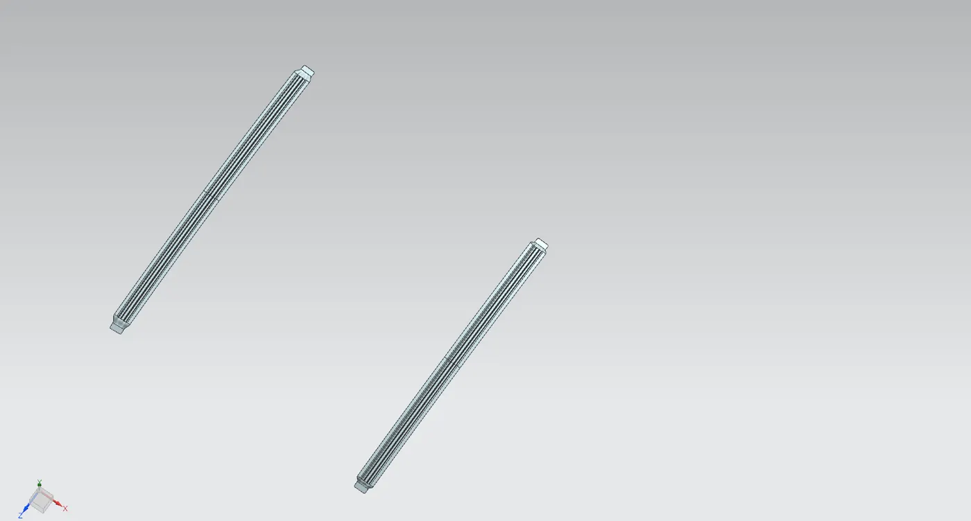
Design of Center roof reinforcement rail
The center roof reinforcement rail is created in a similar way to that of the bow roofs. This is designed using the provided master section and outer panel as a reference.
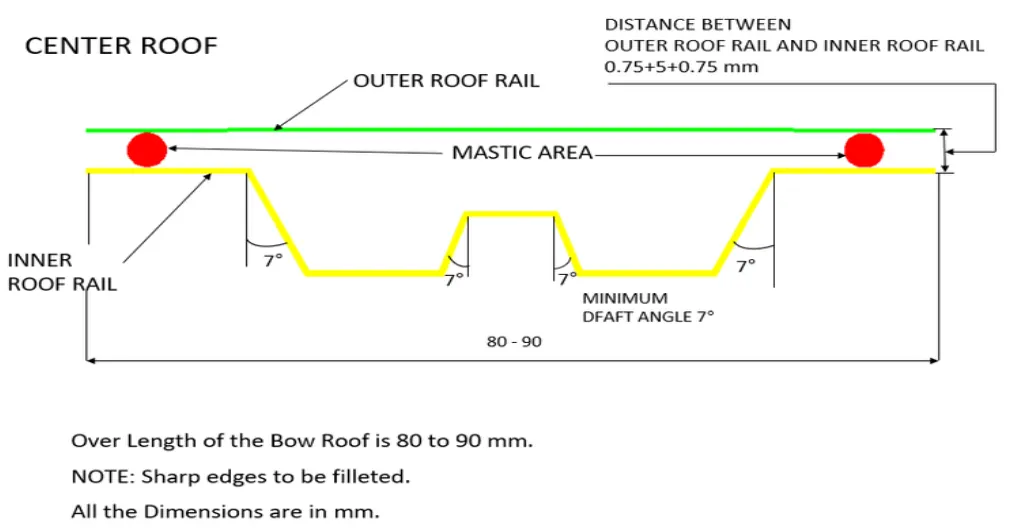
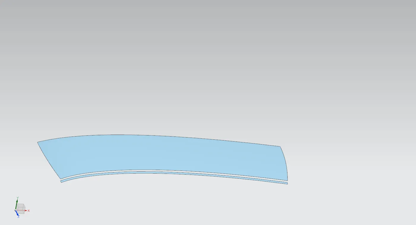
- First a new datum plane is created along the curve on the outer panel at an offset of 50% arc length so as to create the reinforcement rail at the center region of the roof.
- An intersection curve command is used to generate a curve along the surface through the plane.
- Using this curve other curves for the flanges of the rail are made by offsetting curves from this over the surface.
- Curves are created on each side two curves at 15mm and 35mm towards the front side and three curves at 15mm, 30mm and 50mm towards the rear side.
- The overall width of the reinforcement rail will be 85mm.
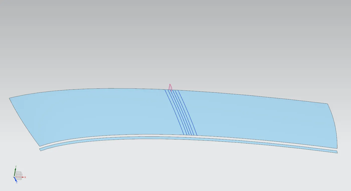
- Now following the steps as in creation of bow roofs the surface is offset at three regions i.e at 6.5mm, 3mm downwards the first flange, 5mm downwards second flange.
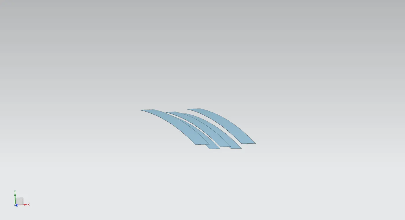
- From these the surfaces are joined together using law extension at an angle of 7deg.
- The excess regions are trimmed off using extend and trim command making corners.
- These regions are joined together using sew command.
- Edges are given edge blend to avoid sharp bends in the sheet.
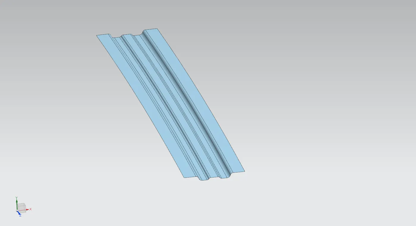
- The ditch region from the outer panel is offset to a distance of (.75*2+.2mm) and a small region parallel to the rail is trimmed.
- This region is to be joined with the center rail.
- Bridge curves are used to create guides from the rails towards ditch region.
- A new surface is made using through curve mesh command using the edges of these regions as primary curves and bridge curves as the guides.
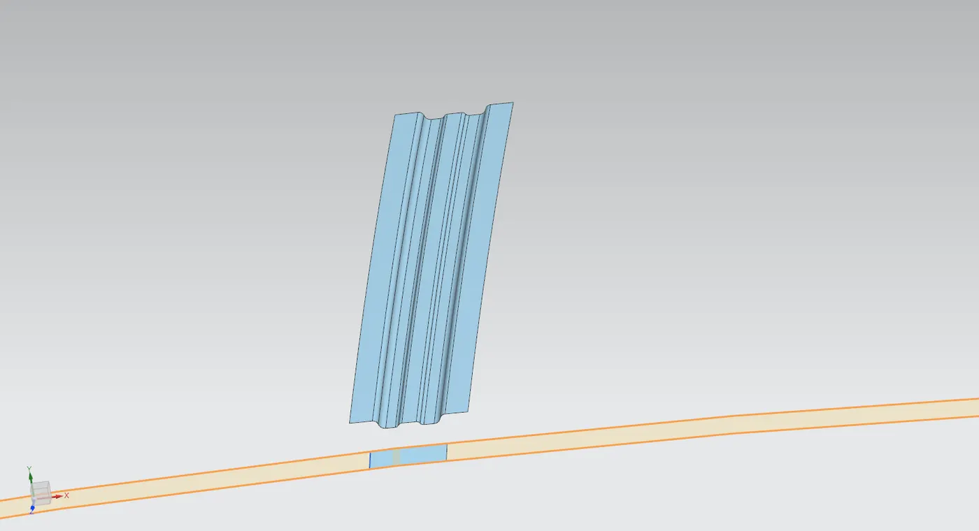
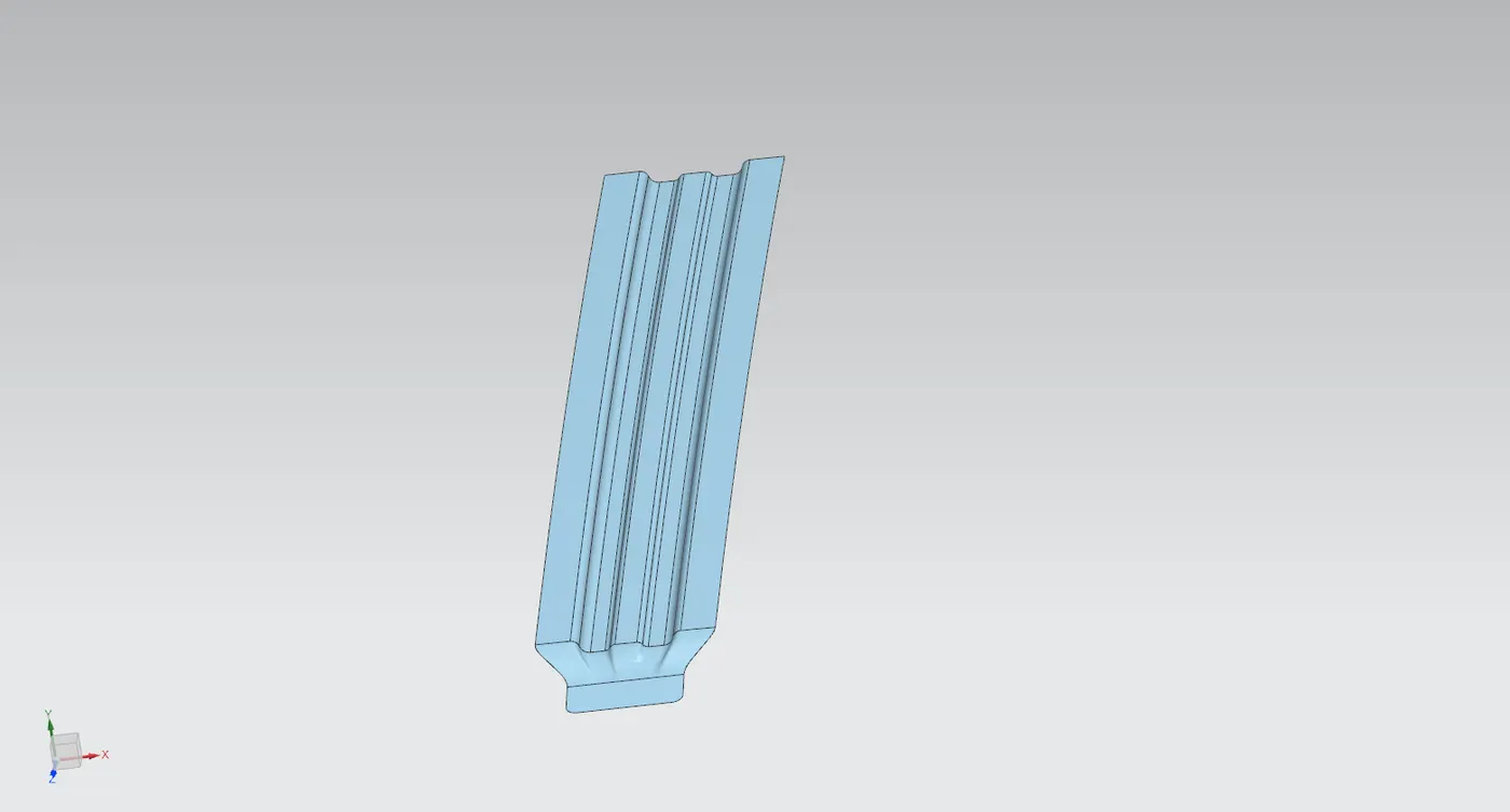
- The regions are joined together using sew command.
- The created geometry is mirrored along the XY plane to obtain a complete center reinforcement rail.
- The two halves are joined together using sew command.
- Thickness of 0.75mm is given using thicken command.
Bow roof prediction Formula (Heat Distortion Formula)
W = [1.73 x 10^(-3) x L] + [1.85 x 10^(-8) x (R^2)/t] + [ 1.10x10^(-3) x l] - 2.68
Where,
L = Roof Length in X-Direction[mm](Roof dimension in 0-Y)
R = Roof curvature
R = 2(Rx*Ry)/(Rx+Ry)
Rx = X curvature
Ry = Y curvature
t = Roof plate thickness [mm]
l = Bow Roof Span [mm]
- To calculate heat distortion a sketch needs to be created through which we can extract the required data.
- A surface is created parallel to the outer roof for sketching.
- A center line is drawn along O-Y axis.
- A line is offset 300m in downward direction, from this 2 more lines are constructed 100mm apart on each side.
- The whole roof section is divided at equal lengths (410mm used here).
- Similar to previous step 2 lines are constructed 100mm apart to these lines as well.
- The intersecting points are projected to the roof.
- The points are used to obtain Rx and Ry values using 3 point Arc command.
The values obtained from the study are tabulated as follows:

Judgment Condition
OK< 2.7
Since all the values for w are less than 2.7, the design is qualifying the criteria.
Snow load prediction formula
Qr = [Iy x t2] / [α x s x [(Rx + Ry)/2]2 x 10-8]
Note: The Qr value given over here is correct. There was a typo error in the formula given in the video.
Where,
α = My x Lx2 x 10-12 , My = Y(Ly-Y)
t = Roof plate thickness [mm]
Ly = Distance between the front and rear roof Rails on the Vehicle along with 0Y[mm]
Length of Roof panel with the center point between Roof rail Front /Rear as the front and rear reference point.
Lx = Distance between the Left and Right end of the roof on the Roof BOW [mm]
The width of the roof panel is exposed on the surface.
Y = Distance front Front Roof Rail to Roof BOW[mm]
s = Distance for which Roof BOW bears divided load [mm]
s = L1/2 + L2/2
Iy = Geometrical moment of inertia of Roof BOW (Y cross-section )[mm4]
Rx = Lateral direction curvature radius of roof panel Y cross-section on Roof BOW [mm]
Roof panel curvature Radius of the Length Lx in Front view
Ry = Longitudinal Direction curvature radius of the Roof panel X cross-section on Roof BOW [mm]
Roof panel X curvature radius of length s in Side view.
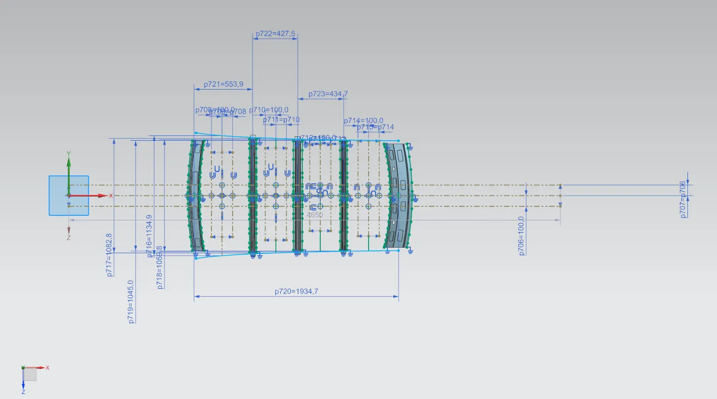
- Similar to heat distortion prediction sketches are required to obtain values for calculations.
- A surface is created parallel to outer roof for sketching.
- A center line is drawn along O-Y axis.
- Two curves are created on either side of this line, each 100mm apart.
- The outer edges from all the roof rails are projected to the sketching surface.
- Center line between each roof rails are created, from these center lines 100mm offset lines are made on either directions.
- Points are created on the sketch and projected to the roof surface.
- The points are joined using arc command to obtain Rx and Ry values, other values are obtained from the sketch.
- To find Iy use cross section of each bow separately to find section modulus (keeping section as solid in the operation parameters)
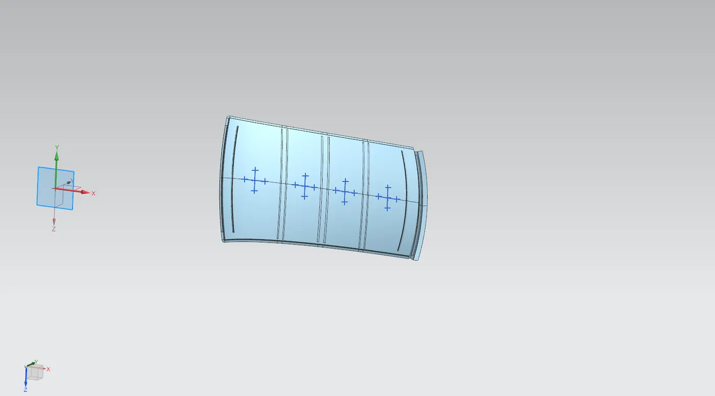
The value obtained from the study are tabulated as follows:

Judgment condition
Qr ≥ 3.1
In this design it is observed that towards the rear of the roof it fails to clear snow load criteria.
To make the design feasible there are 3 solutions which are to be implemented:
- The section modulus of the bow roofs can be improved further.
- The mastics regions can be increased.
- Emboss over the roof outer surface towards the rear.
Updated Design
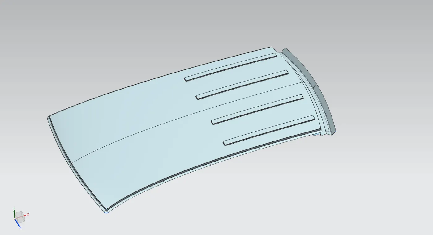
Draft Analysis
Front roof rail
Rear Roof Rail
Bow Roof 1
Bow Roof 2
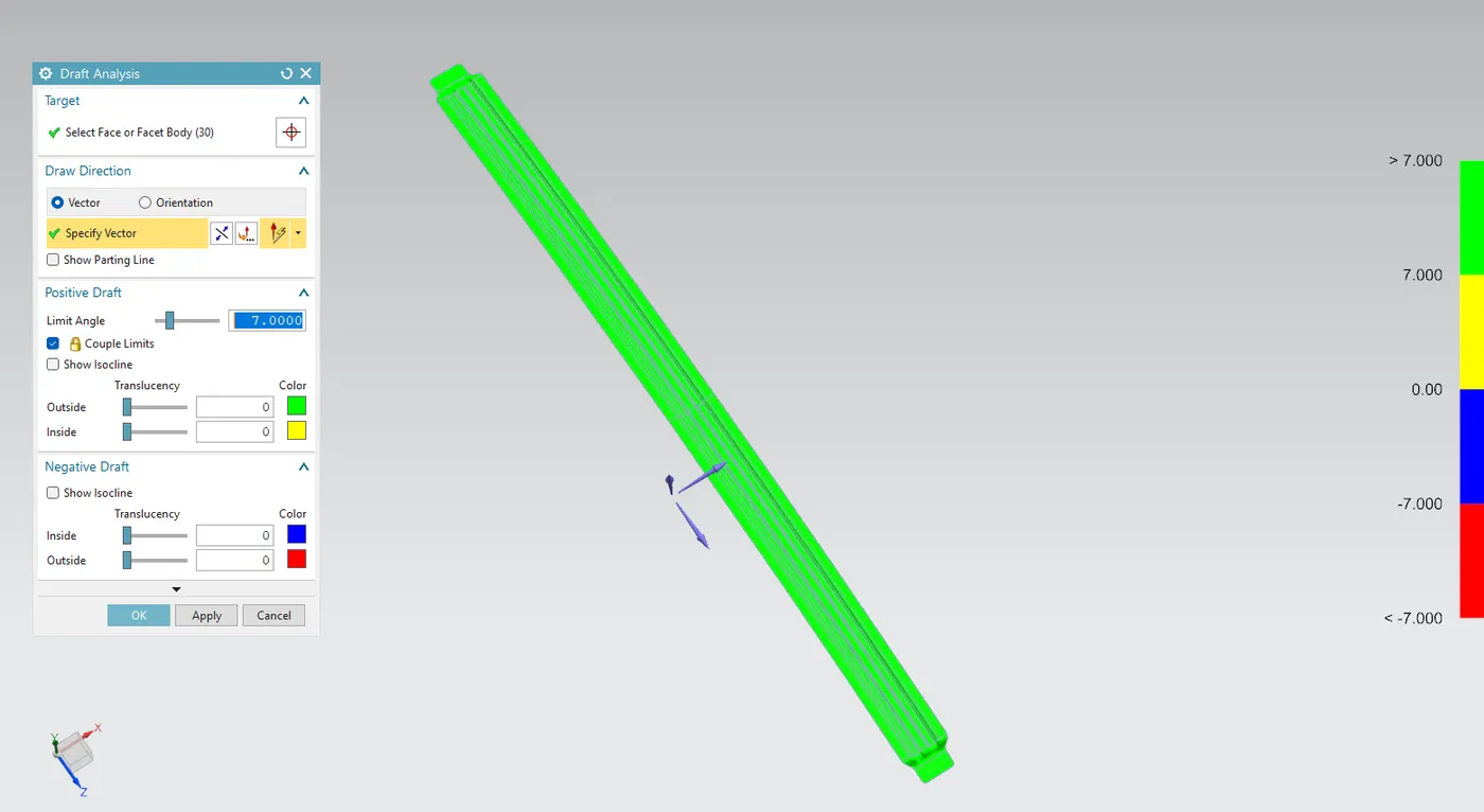
Center Reinforcement Roof
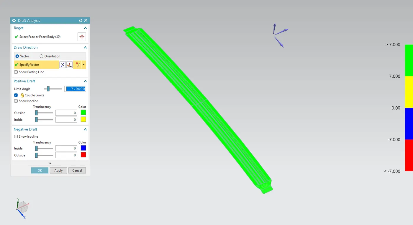
Final Design
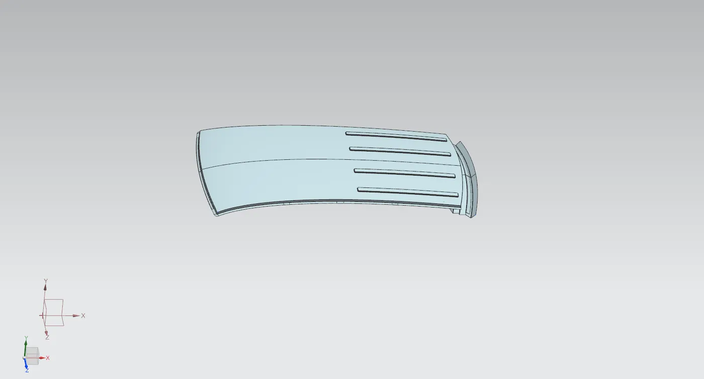
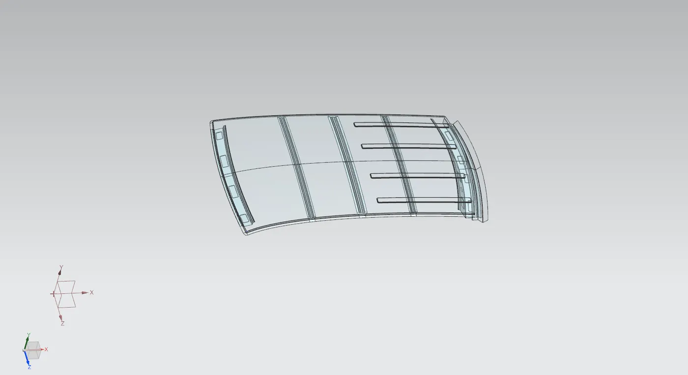
MANUFACTURING PROCESS
Metal Stamping Process
Metal stamping is the manufacturing process where flat metal sheets are converted to specific shapes through a number of metal forming techniques like bending, blanking, punching etc.
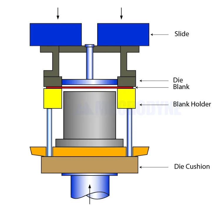
It involves placing the flat sheet metal in blank form into a stamping press. using a tool and die surface form the metal into desired shape. There are several types of metal stamping methods like progressive die stamping, fourslide stamping, short run stamping but for the manufacturing of automotive components mostly deep draw stamping is utilized.
Deep Draw Stamping
This method involves pulling a sheet metal blank through the die via a punch, which results in required shape. This is called "deep drawing" when the depth of the drawn part exceeds it's diameter. This a simple and cost effective method to manufacture seamless components thus widely used in automotive industry.
Welding
Welding is one of the major manufacturing process involved in the automobile sector as the major components in them being metal. There are several methods used for different metals and for desired outcome, but the major welding process involved during production is resistance spot welding. Others include MIG welding, TIG welding, laser beam welding.
Resistance Spot Welding
In this welding technique two metal sheets are pressed in between copper electrodes. An electric current passes through the points of contact which heats up and melts the metal thus joining them.
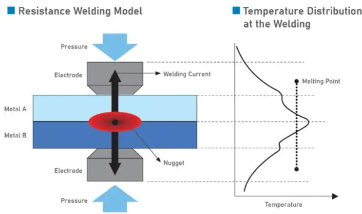
This method is widely used because it produces clean and smooth welds, moreover the process is simple and easy to automate through a production line. This makes it cost effective in the long run.
Mastic Sealants
Mastic sealants are used to bond inner and outer panels by using a type of synthetic rubber sealant. Once the sealant cures it hardens in turn providing strength to the parts it adheres to. They help to eliminate flexing in panels and provides improvements in NVH levels.
CONCLUSION
A complete design of roof is designed with it's components including outer roof panel, bow roofs, front and rear roof rails and center reinforcement rail. Heat distortion and snow load study are conducted on the roof, the results indicate that there is inadequacies in strength towards the rear of the roof in snow load prediction study. The design is modified to accommodate for the lack in strength by providing embosses on outer panel and increasing the mastic region.