Design of backdoor
BACK DOOR DESIGN
OBJECTIVE
- To design a back door for an automobile using provided styling surface by incorporating appropriate design methodologies.
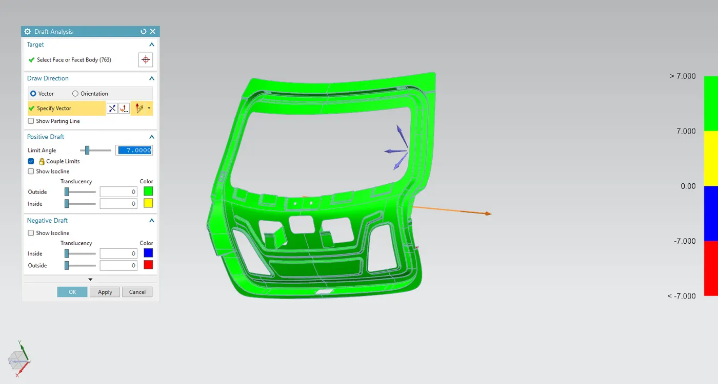
- To study the manufacturability of the designed part with help of draft analysis
- To study the various manufacturing processes involved in the production.
INTRODUCTION
Back door or a tailgate of a vehicle refers to the closure component at the rear side of the vehicle which allows for the access towards the rear side which may be boot-space to keep luggage, back-row seats or to even access the spare wheel.
Classification of back door
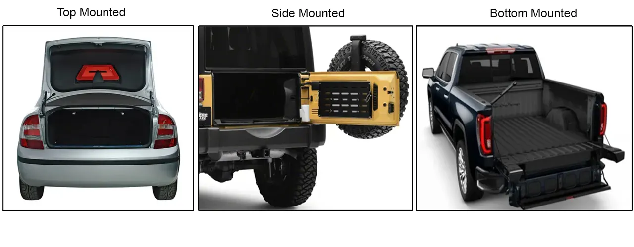
The back door can mainly be classified based on the mounting of the hinges:
- Top mounted door - Here the door opens upwards. The most common style back door design found in hatchbacks and sedans.
- Side mounted door- Here the door opens towards one side. Mostly found in SUVs like Jeep Wrangler.
- Bottom mounted door - Here the door opens downwards. Mostly found in pickup-trucks.
Nowadays most manufacturers offer automatic tailgates for easy access (Mainly in top variants), so another classification can be used based on manual or automatic operation.
Components of back door
- Inner panel.
- Outer panel.
- Wiper motor reinforcement.
- Hinge and reinforcements.
- Latch & Striker with reinforcements.
- Strut mounts with reinforcements.
Design Considerations for Back door
Apart from provided styling data and master sections there are several other factors that come into action when designing the back door. This impacts greatly on functionality and safety over aesthetics.
- Rear visibility criteria regulations.
- Crash impact criteria for safety regulations.
- Gap and flushness criteria.
- Manufacturability.
Design of Back door in NX CAD
First step is to obtain Class A surface styling data, along with other requirements, in this case sheet metal thickness is of 0.75mm
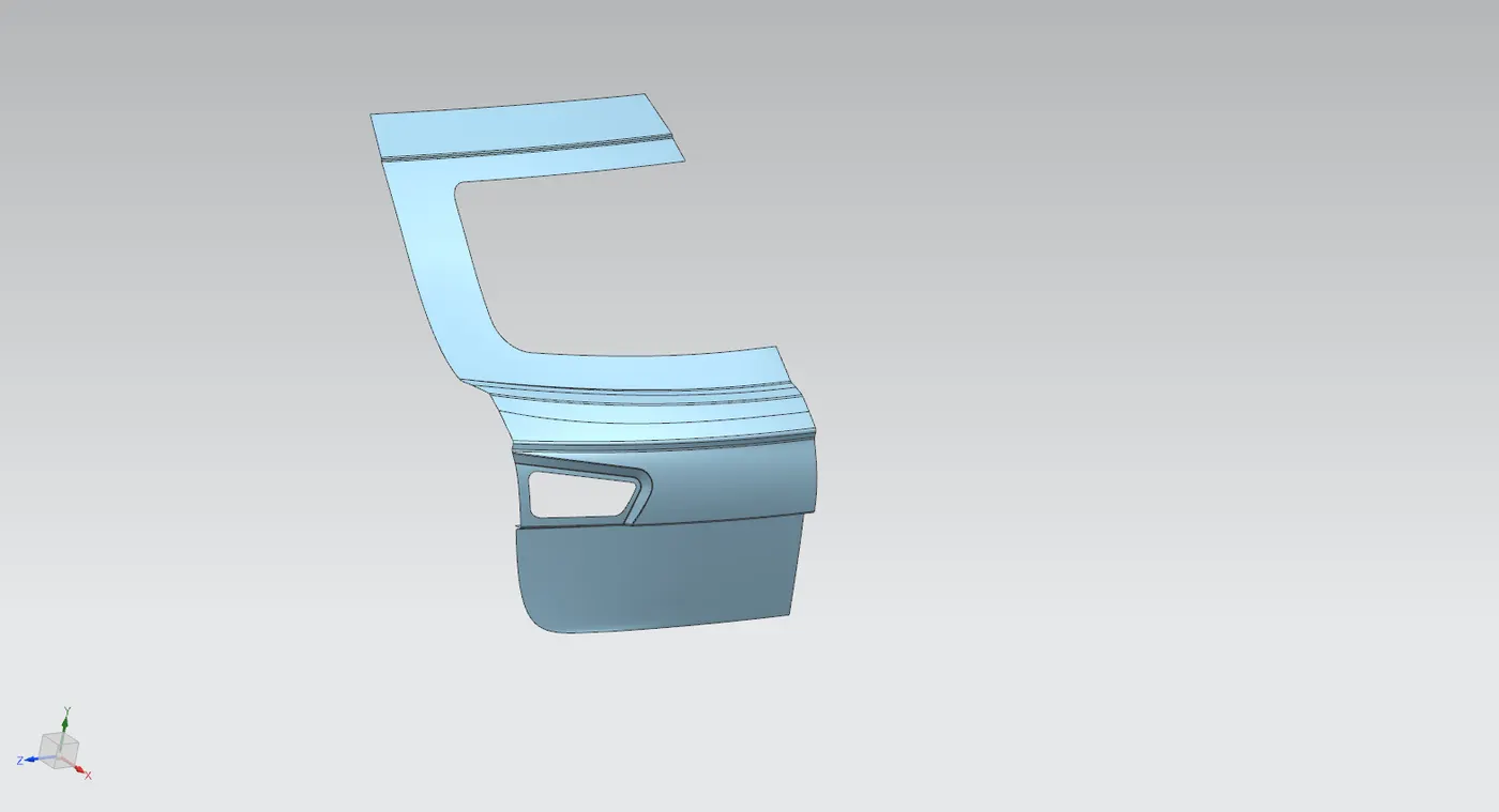
The provided surface is not complete and has some minor flaws. Now we have to rectify these issues before proceeding to obtain a smooth surface to begin with design of other components.
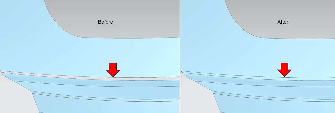
Starting by trying to sew the various faces one by one using sew command, when there is an issue error throws up by the software which indicates irregularities in the surface.
These surfaces are suppressed and new ones are made using help of bridge curves and through curve mesh commands. This step is repeated until all the surfaces can be sewed together.
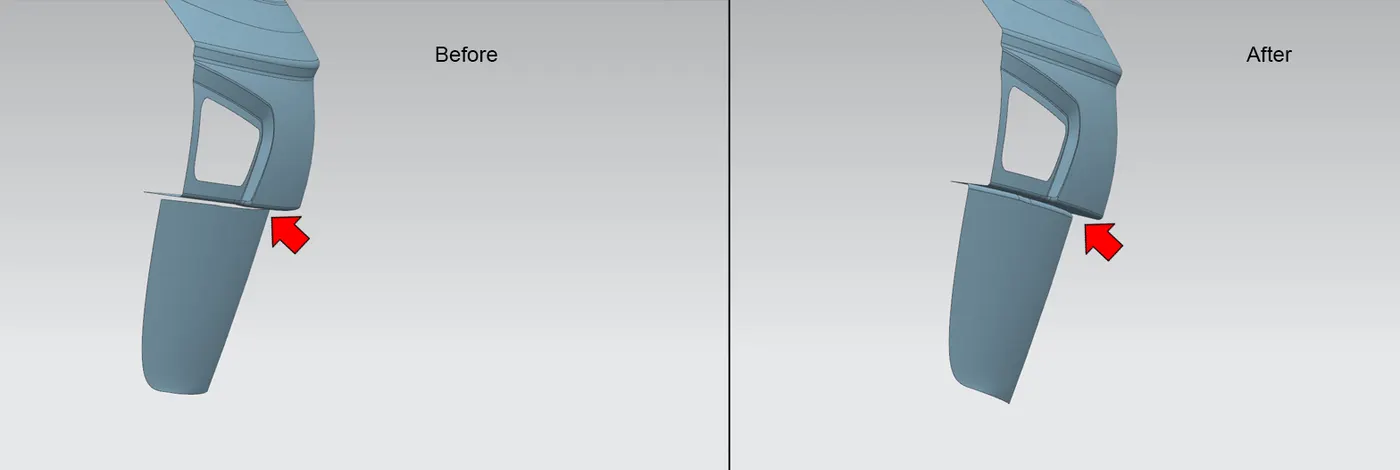
The outer surface is made of 2 different components or sheets, the bottom part is incomplete without the flange to be spot welded onto the top surface.
We create a surface for spot welding on the bottom part by extending the sheet on the part above and extracting that same face downwards and making a single part towards the bottom with help of trim and extend command. Face blends are applied to remove sharp corners.
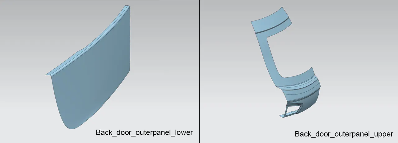
Two separate parts are extracted from the provided class A surface and saved separately as outer panel upper and outer panel lower.
Design of inner panel
- The outer panel lower and upper geometry are extracted to a new part file inside the assembly to create the inner panel.
- The surfaces are used as a reference to create the tooling direction required for deep drawing.
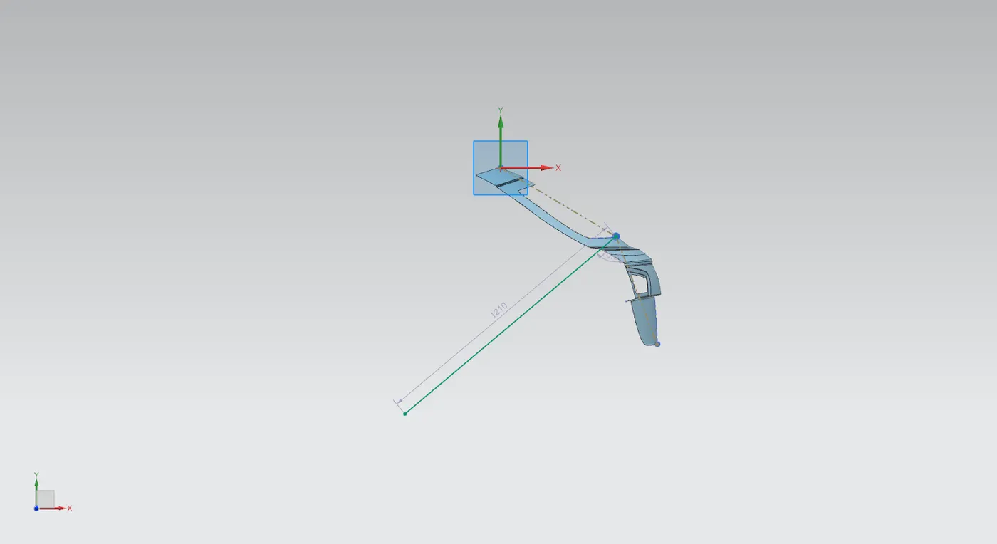
- The surfaces are both offset to a distance of 1.7 mm(0.75+0.75+0.2) inwards in order to create the flange required to make the inner panel seal region.
- The upper surface is sliced up to required width (30 mm ) using offset curve in face command at required locations to create the flange.
- The straight cut surfaces are joined together using two bridge curves followed by a through curve mesh command to create the curved surface.
- The procedure is continued to create the whole flange.
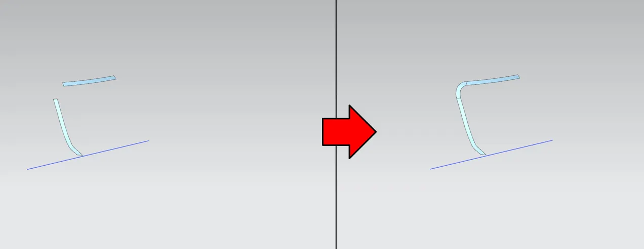
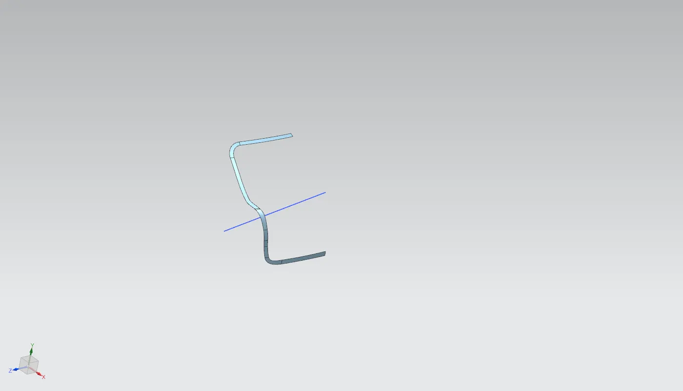
- A new surface is created to meet the already existing offset surfaces of upper and lower outer panel using a law extension command at 35deg, following the tooling direction.
- The law extension is used to trim the sheet metal surfaces to create the next flange using trim and extend command.
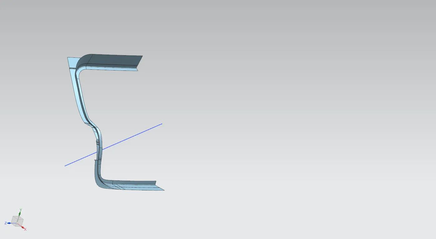
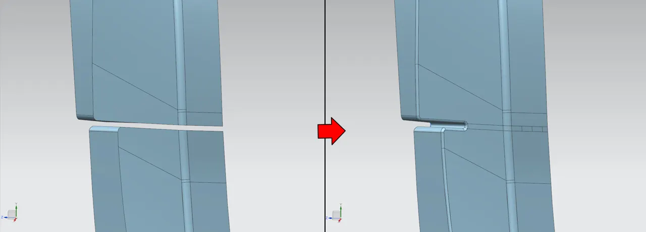
- The two surfaces are separate as upper and lower outer panels are separate.
- These parts are joined together using two bridge curve between them and using through curve mesh command.
- The rest of the part (longer region) is made using a studio surface command.
- Edge blends are used to remove sharp edges.
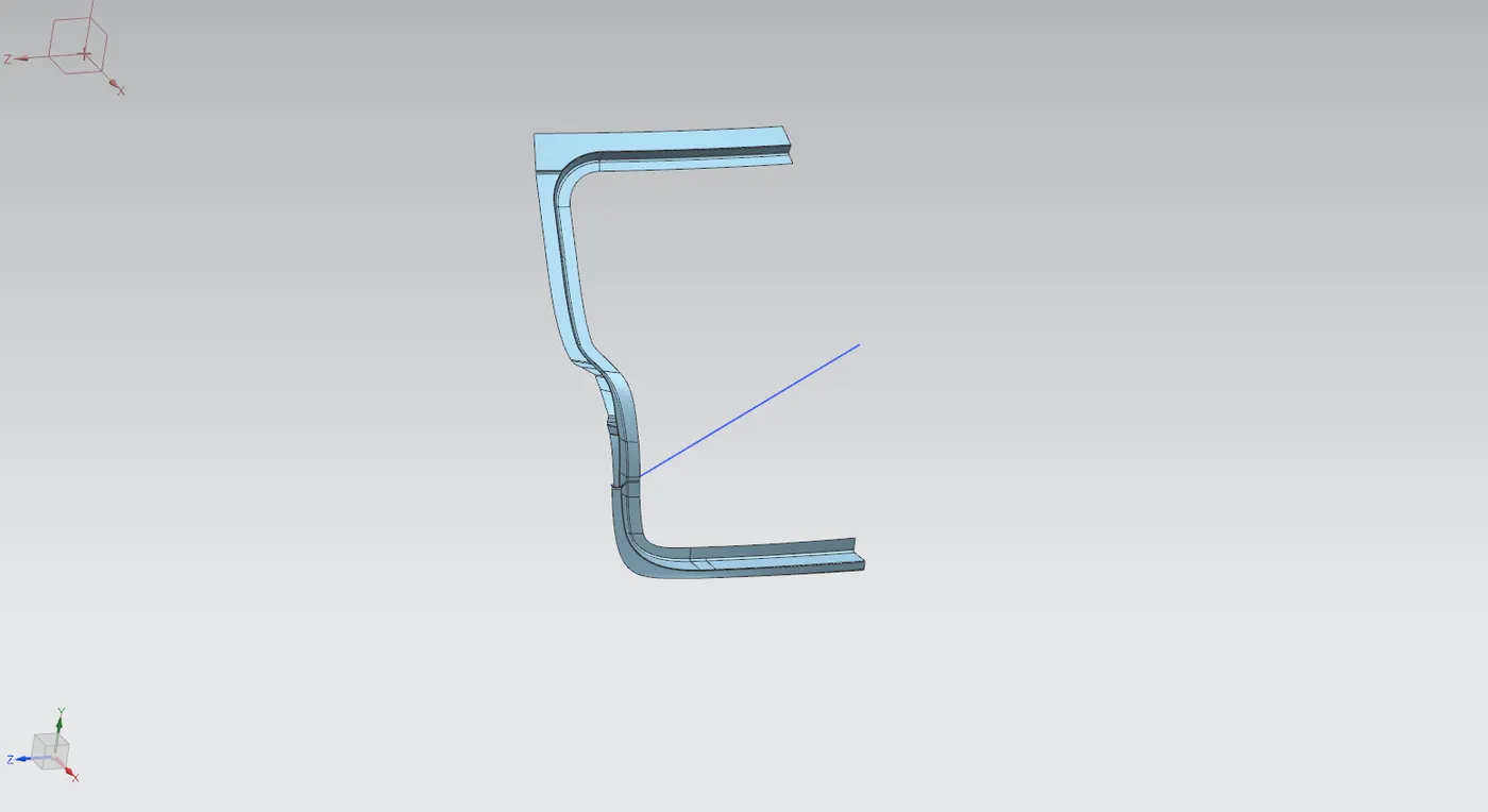
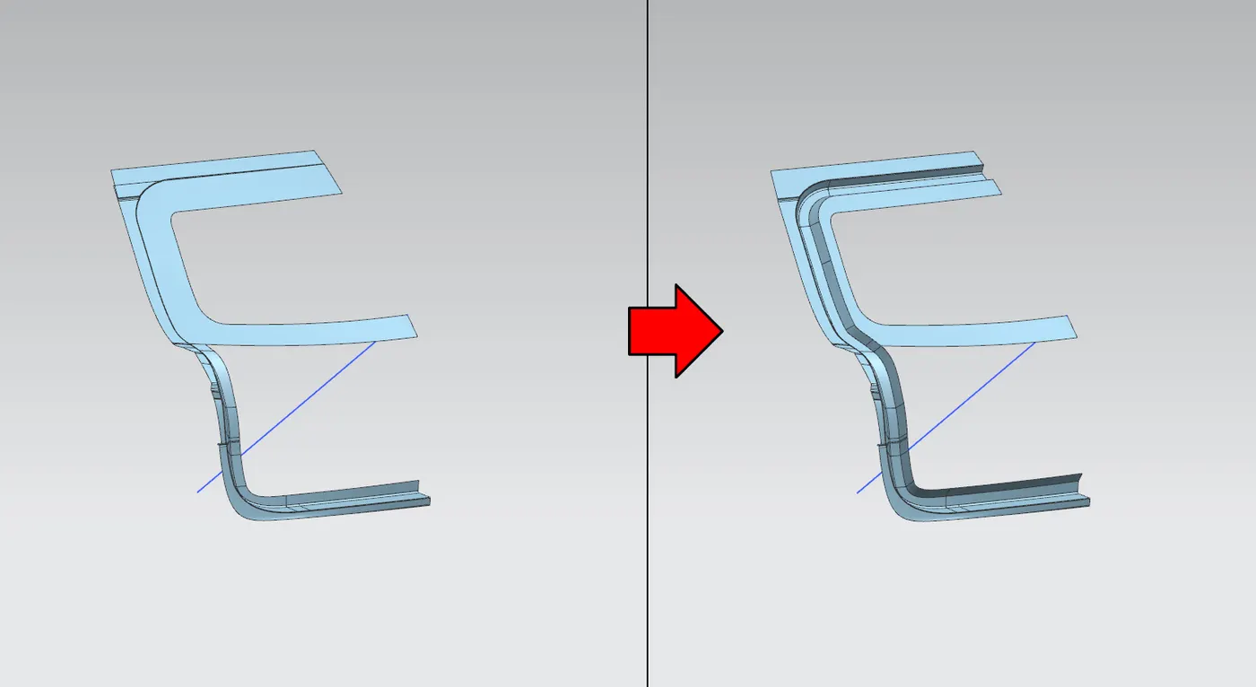
- To create the windshield region another surface from the upper outer panel is offset inwards a distance of 1.7mm.
- This surface is combined with previous surface using a law extension from the lower flange extending upwards to the windshield region.
- To create the lower region, two bridge curves are made from either edges left from the surface of the windshield region.
- These bridge curves are used as guides to create new surface with studio surface command.
- The excess gap is covered using extend sheet command and trimming it with the law extension surface to create an edge, which is followed by edge blends to remove sharp edges.
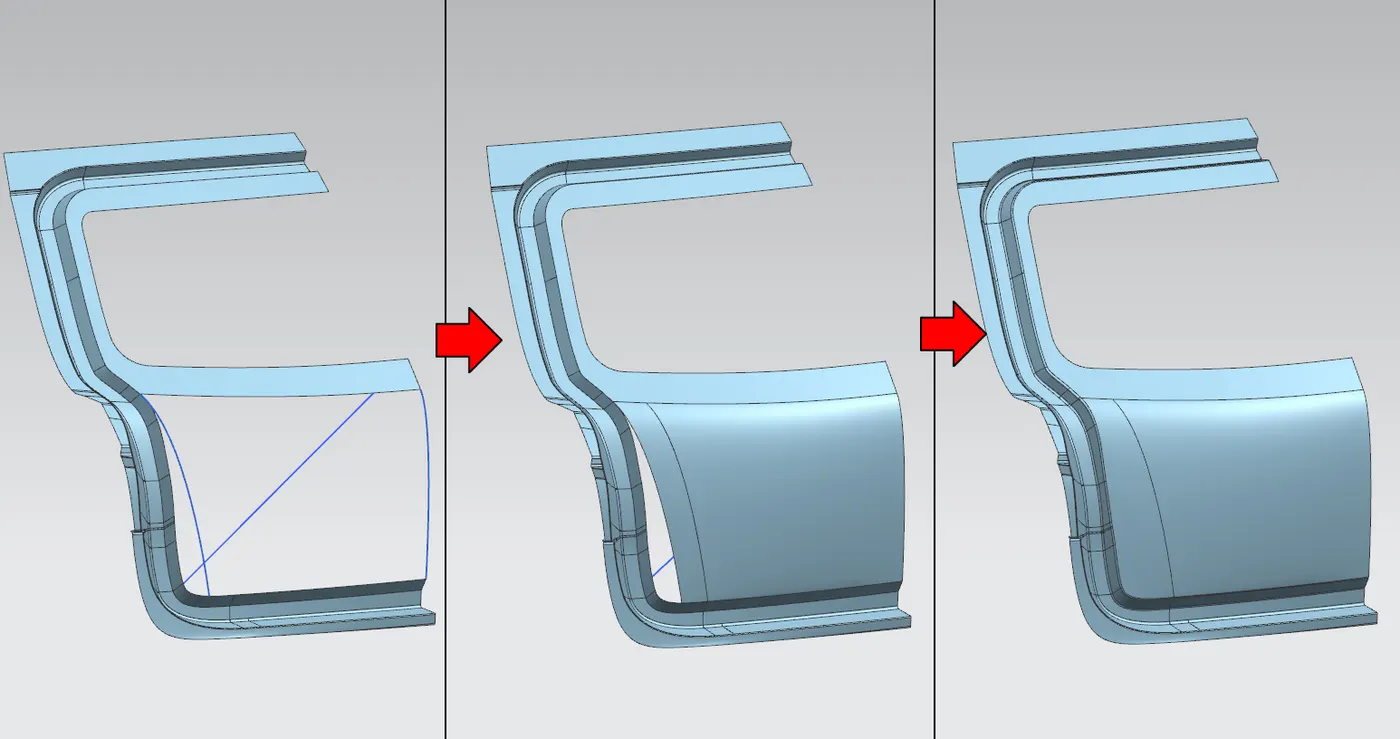
- For providing additional support using mastic sealants, a surface is made to mate with the outer panel upper such that a 5mm clearance is maintained to apply mastics.
- A cutout is made in the surface with help of sketch tool, from which a law extension is made to join the mating surface to the inner panel.
- Edges are given edge blend to avoid sharp edges, and reliefs are created at the starting of law extension.
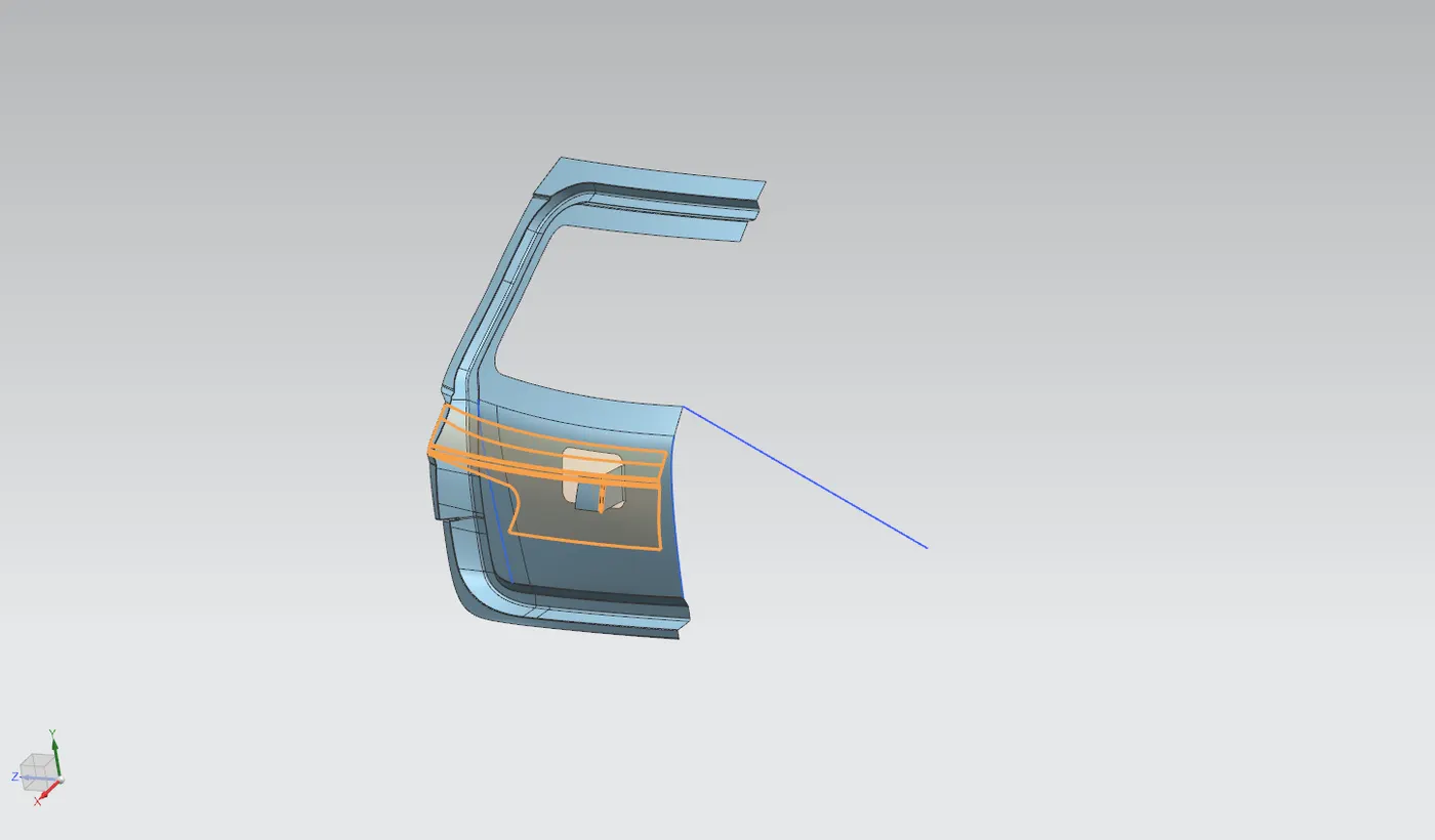
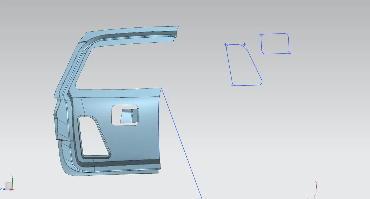
- Cut out is made to allow for installation of tail lamps, this can also be considered as a weight reduction on the inner panel.
- Sketch is made and projected on the surface, this is given a slight emboss with draft angle of 12 deg, with draft direction along created tooling direction.
- The final surface is offset on itself inwards and trim sheet command used to create a hole.
Multiple embosses are made to provide strength to the inner panel.
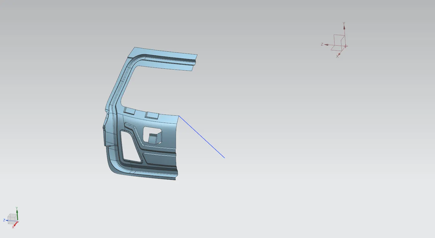
- The whole geometry is mirrored to create a complete inner panel.
- On this cutouts for wiper motor mount, striker mount, hinge mount and strut mount locations are created using sketches and embosses.
- A cut out is made at center to assist in mounting of wiper motor.
- Surface is given a thickness of 0.75 mm using thicken command.
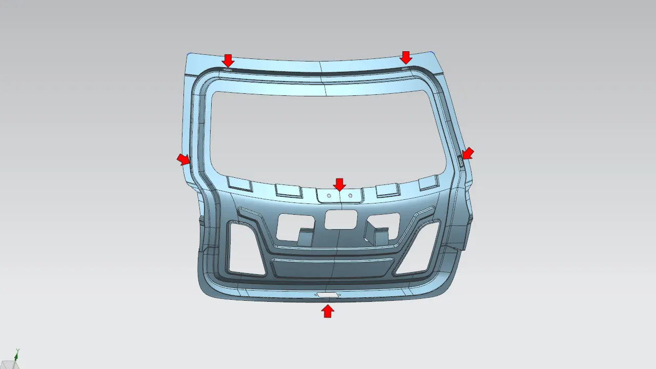
Design of hinge reinforcements
- New part file is created inside the assembly for hinge reinforcement (LH side), this model is later mirrored later along central axis to create RH side reinforcement.
- The required surface for creating the reinforcement along the flange is extracted using wave geometry linker into the new part file.
- The extracted faces are combined using sew command.
- The surface is offset upwards at a distance of 0.75mm.
- The excess regions are trimmed off.
- Edges are given smooth curves using curve on surface command and trimmed.
- Thickness of 0.75mm is given using thicken command.
- The same geometry is extracted in another part file and mirror feature command is used for RH side reinforcement.
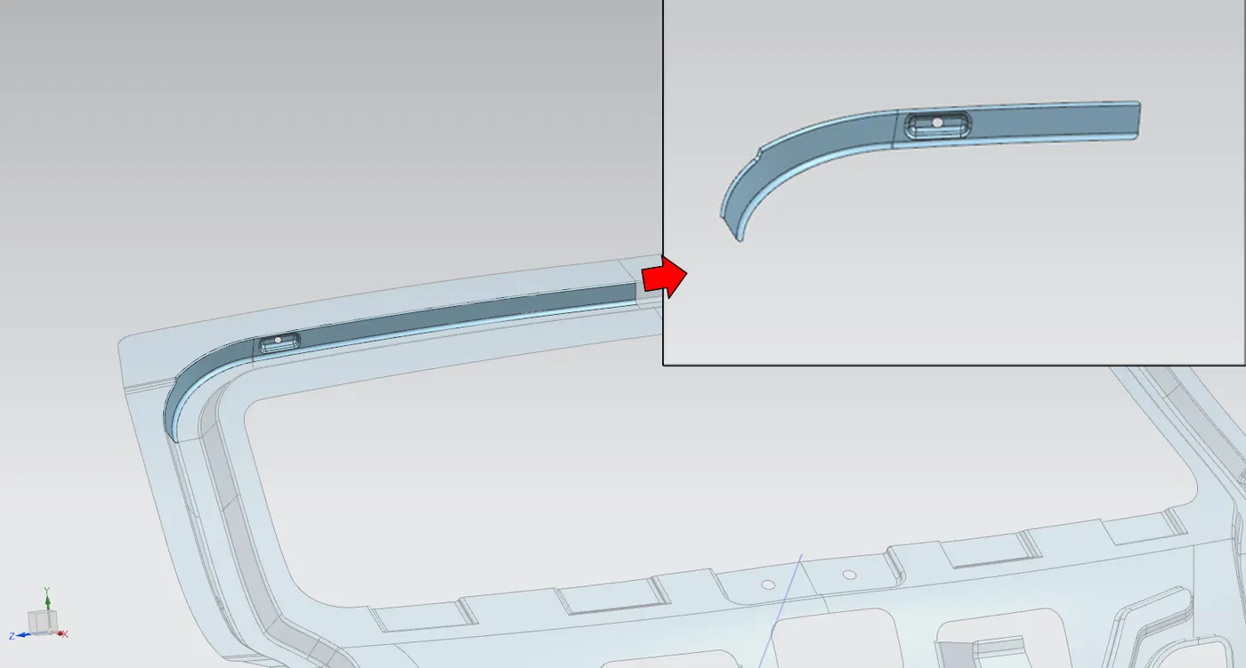
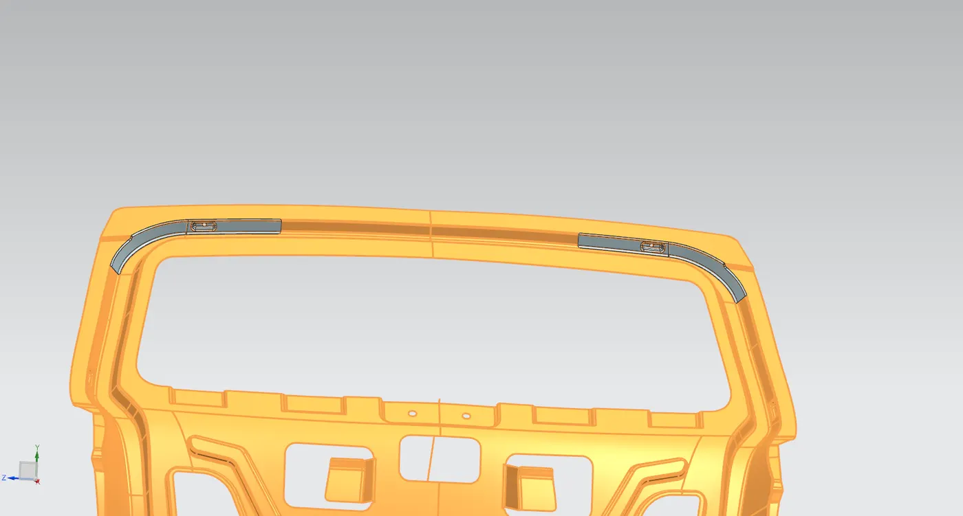
Design of strut mount reinforcements
- Similar to hinge reinforcements, new part file is created inside the assembly for strut mount reinforcement (LH side), this model is later mirrored later along central axis to create RH side reinforcement.
- The required surface for creating the reinforcement along the flange is extracted using wave geometry linker into the new part file.
- The extracted faces are combined using sew command.
- The surface is offset upwards at a distance of 0.75mm.
- The excess regions are trimmed off.
- Edges are given smooth curves using curve on surface command and trimmed.
- Thickness of 0.75mm is given using thicken command.
- The same geometry is extracted in another part file and mirror feature command is used for RH side reinforcement.
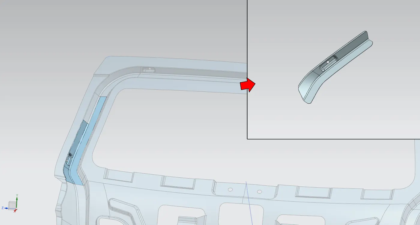
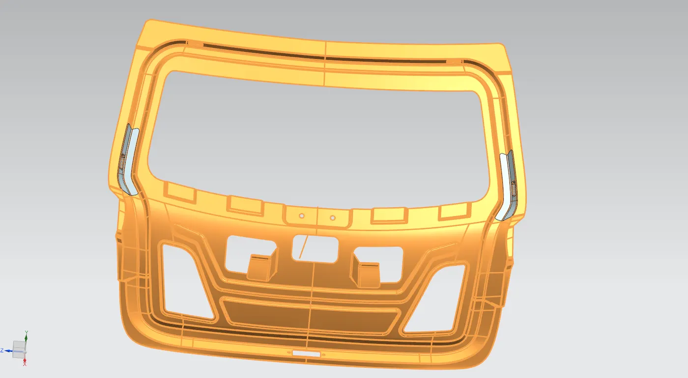
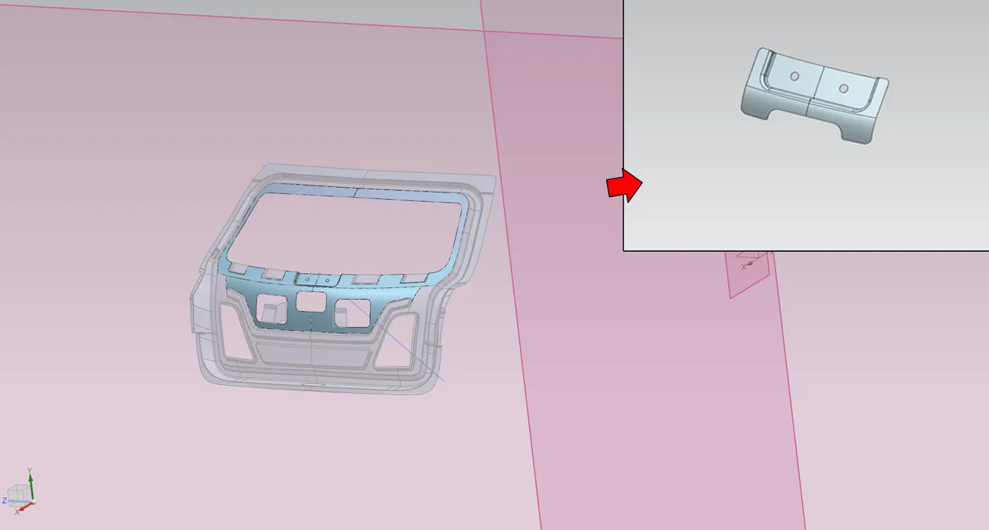
Design of wiper motor mount reinforcement
- New part file is created inside the assembly for wiper motor mount reinforcement.
- The required surface for creating the reinforcement along the surface is extracted using wave geometry linker into the new part file.
- The extracted faces are combined using sew command.
- Excess regions are removed by trimming them off with help of additional datum planes at the desired positions relative to the mount.
- The surface is offset upwards at a distance of 0.75mm.
- Edges are given smooth curves using curve on surface command and trimmed.
- Thickness of 0.75mm is given using thicken command.
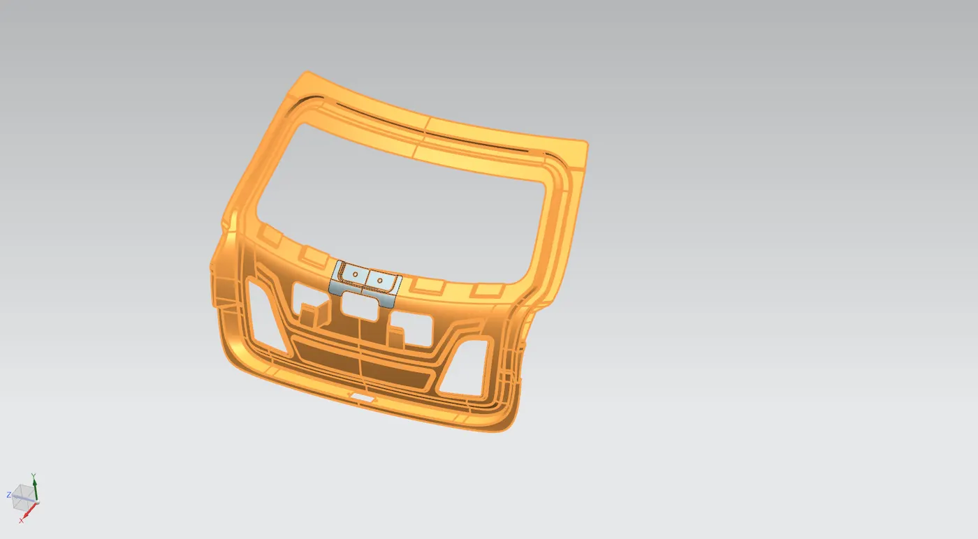
Design of striker mount reinforcement
- New part file is created inside the assembly for striker mount reinforcement.
- The required surface for creating the reinforcement along the surface is extracted using wave geometry linker into the new part file.
- The extracted faces are combined using sew command.
- Excess regions are removed by trimming them off with help of additional datum planes at the desired positions relative to the mount.
- The surface is offset upwards at a distance of 0.75mm.
- Edges are given smooth curves using curve on surface command and trimmed.
- Thickness of 0.75mm is given using thicken command.
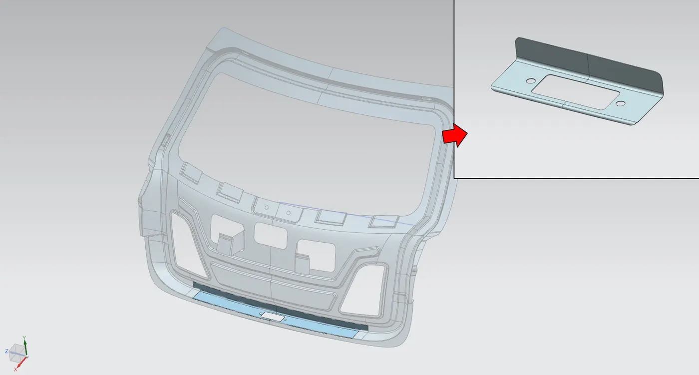
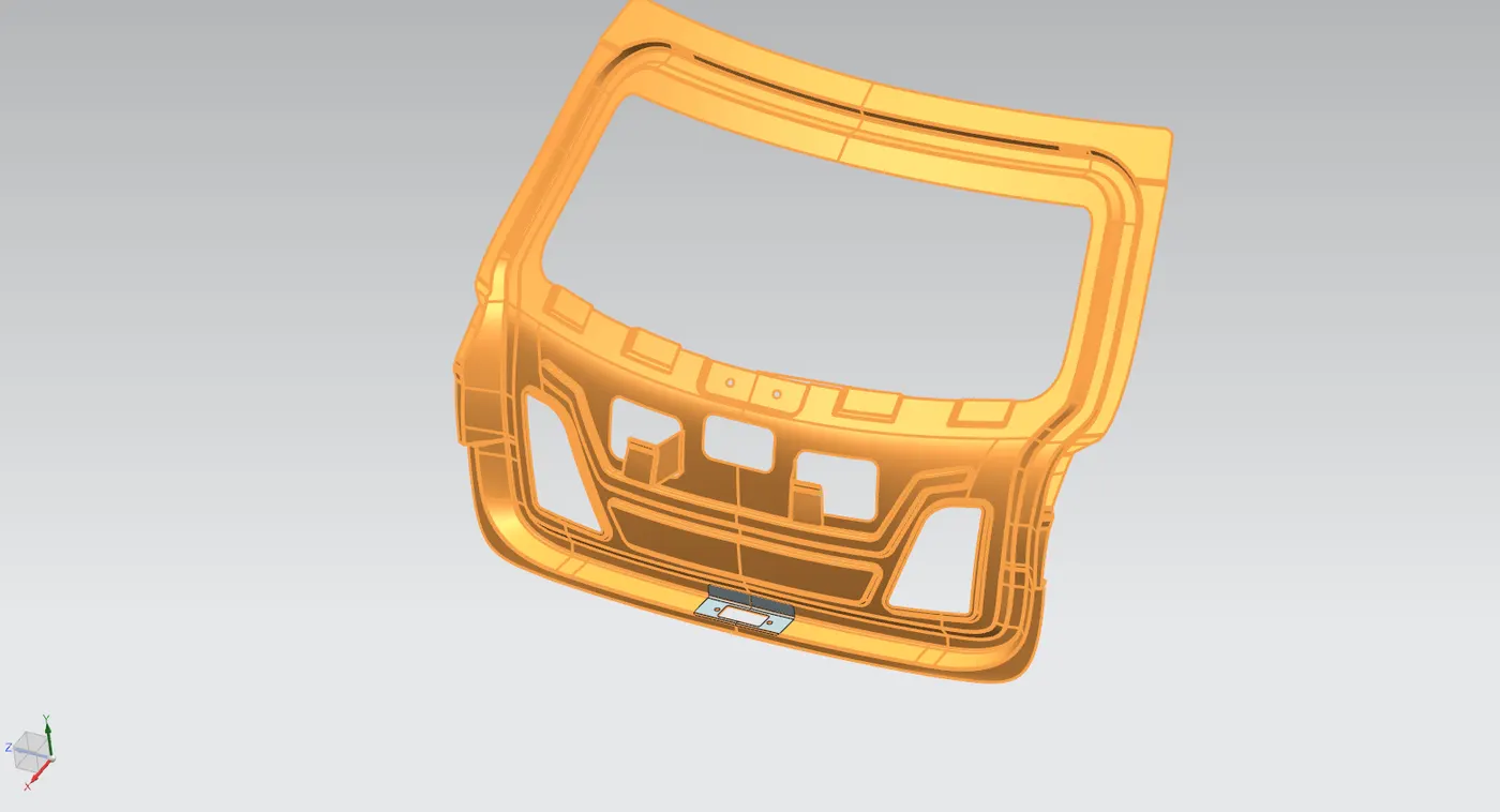
Design of outer panel upper
- The outer panel upper surface created during first step is used here.
- To create lower flange for hemming surface certain surface/faces from the inner panel design are extracted using wave geometry linker.\
- These surface are then offset to a distance of 0.75mm + 0.2mm
- These surfaces are joined together using bridge curves and surface is completed using through curves mesh command.
- The surface is trimmed to have a width of 7mm using offset curve command and project curve command and later trimming unnecessary surfaces.
- This leaves us with a flange for hemming.
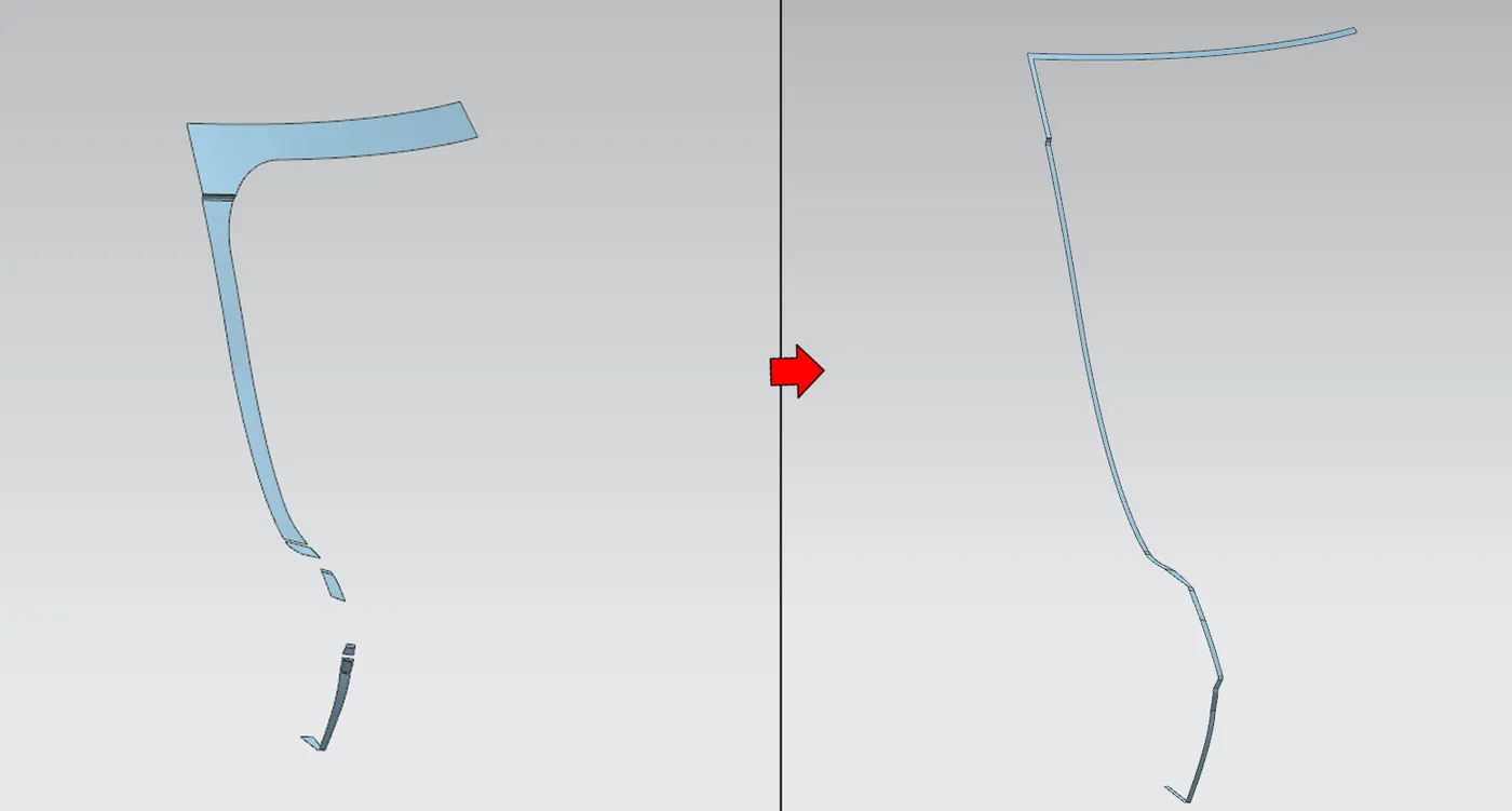
- Bridge curves are used to join (G1 tangency) the upper surface and lower flange at multiple points.
- Swept surface command is used to create joining surface between the two, wherever the geometry fails to do so we resort to through curves mesh to generate the additional surface with the primary curves as bridge curves and guide curves as the edges of the surfaces.
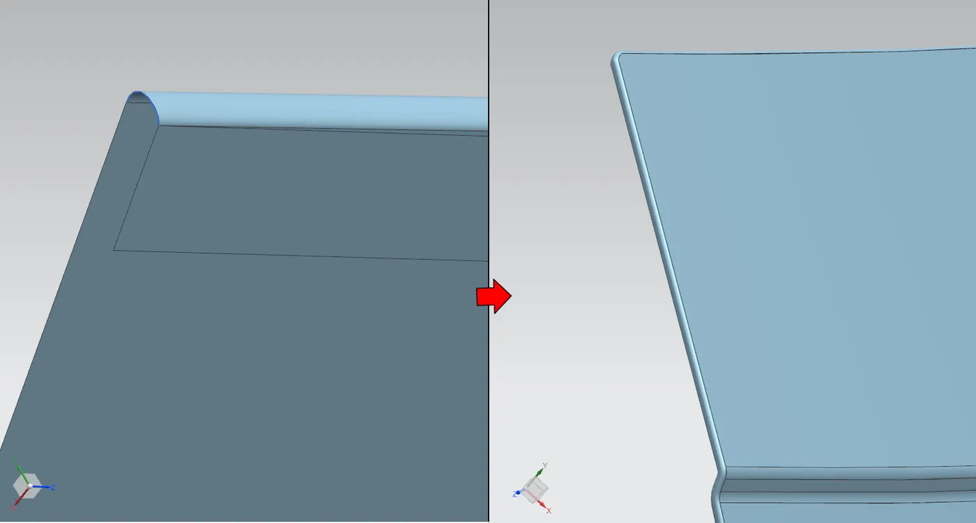
- The geometry is mirrored to form a complete upper panel.
- Reliefs are given throughout the hem region using curve on surface command followed by trim sheet command.
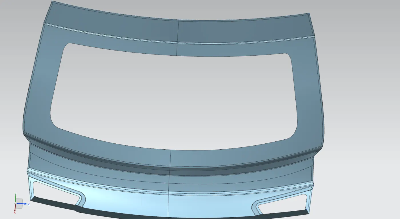
Design of outer panel lower
- Outer panel lower surface created earlier is used as the primary surface.
- This surface is offset downward to a distance of 2.65mm to create the hem flange.
- New sketch is made with the outer edges of the surface and offset to a distance of 7mm. This section is trimmed off to obtain the hem flange.
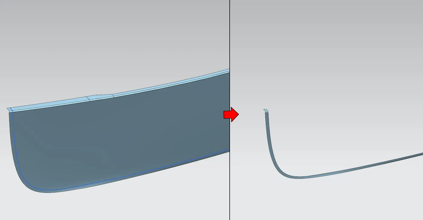
- Bridge curves are made at multiple points along the edges of the two surfaces (G1 tangency).
- This curves are used as primary curves and edges as guide curves in through curves mesh command to create a joining surface for hem.
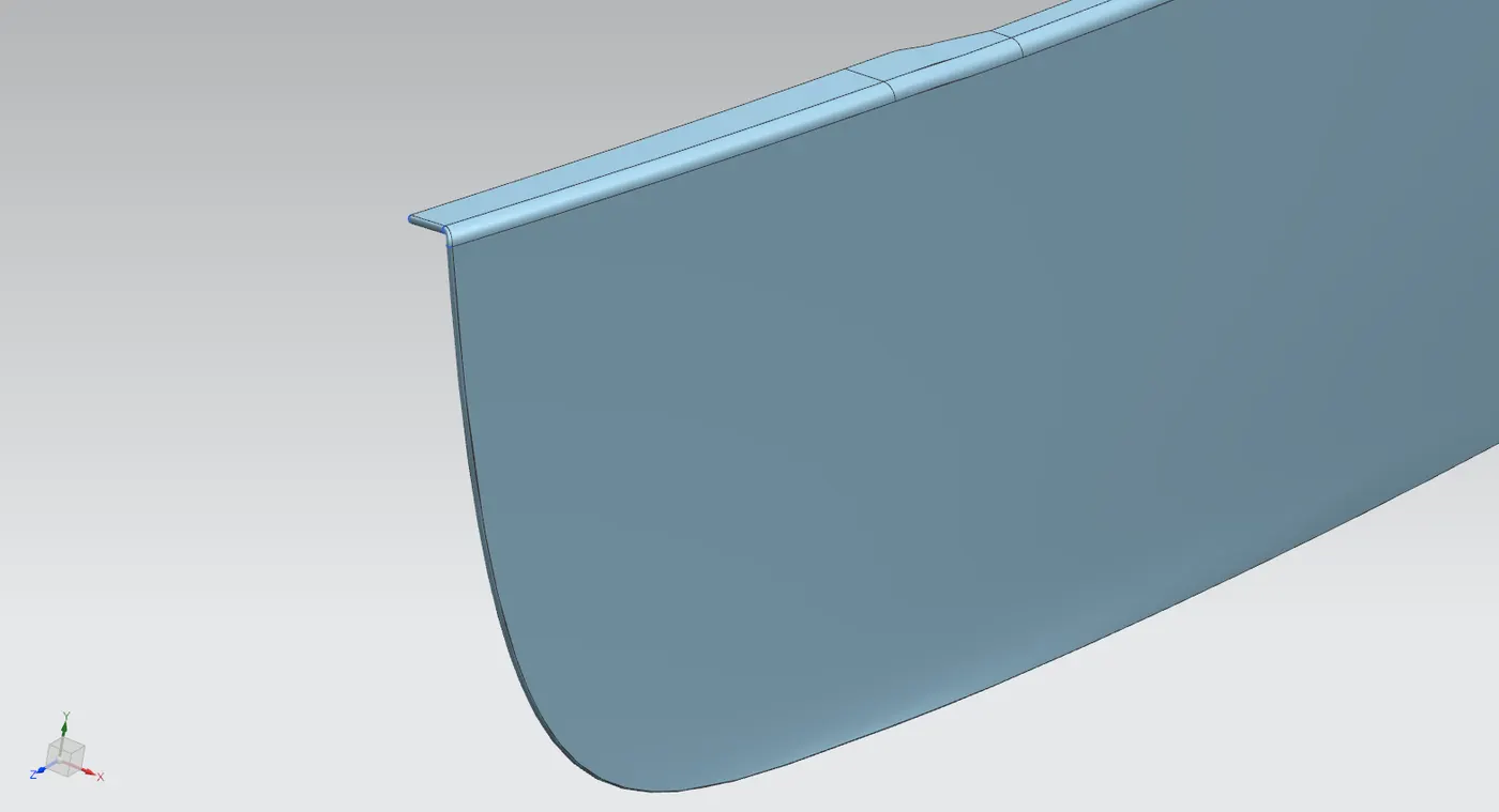
- The geometry is mirrored and joined using sew command to obtain final outer panel lower.
- Reliefs are given throughout the hem region using curve on surface command followed by trim sheet command.
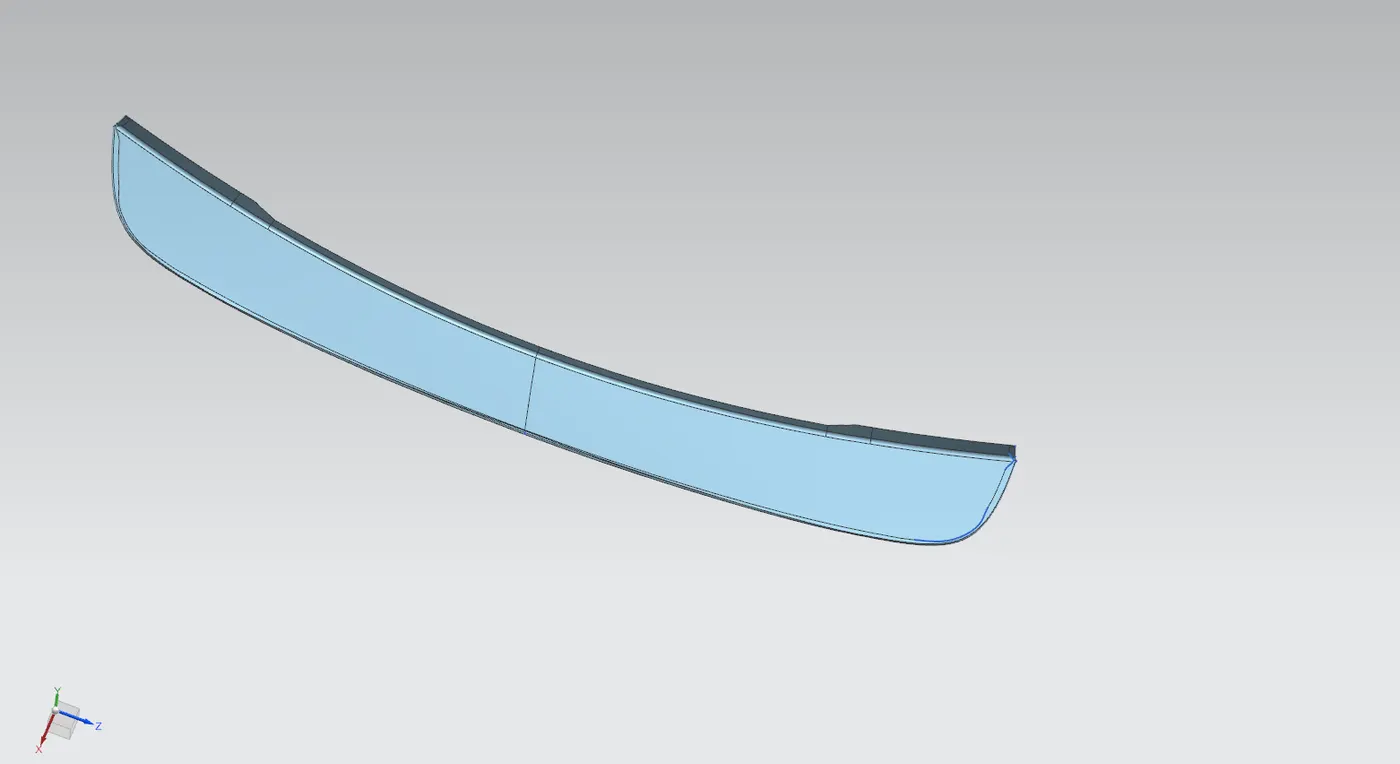
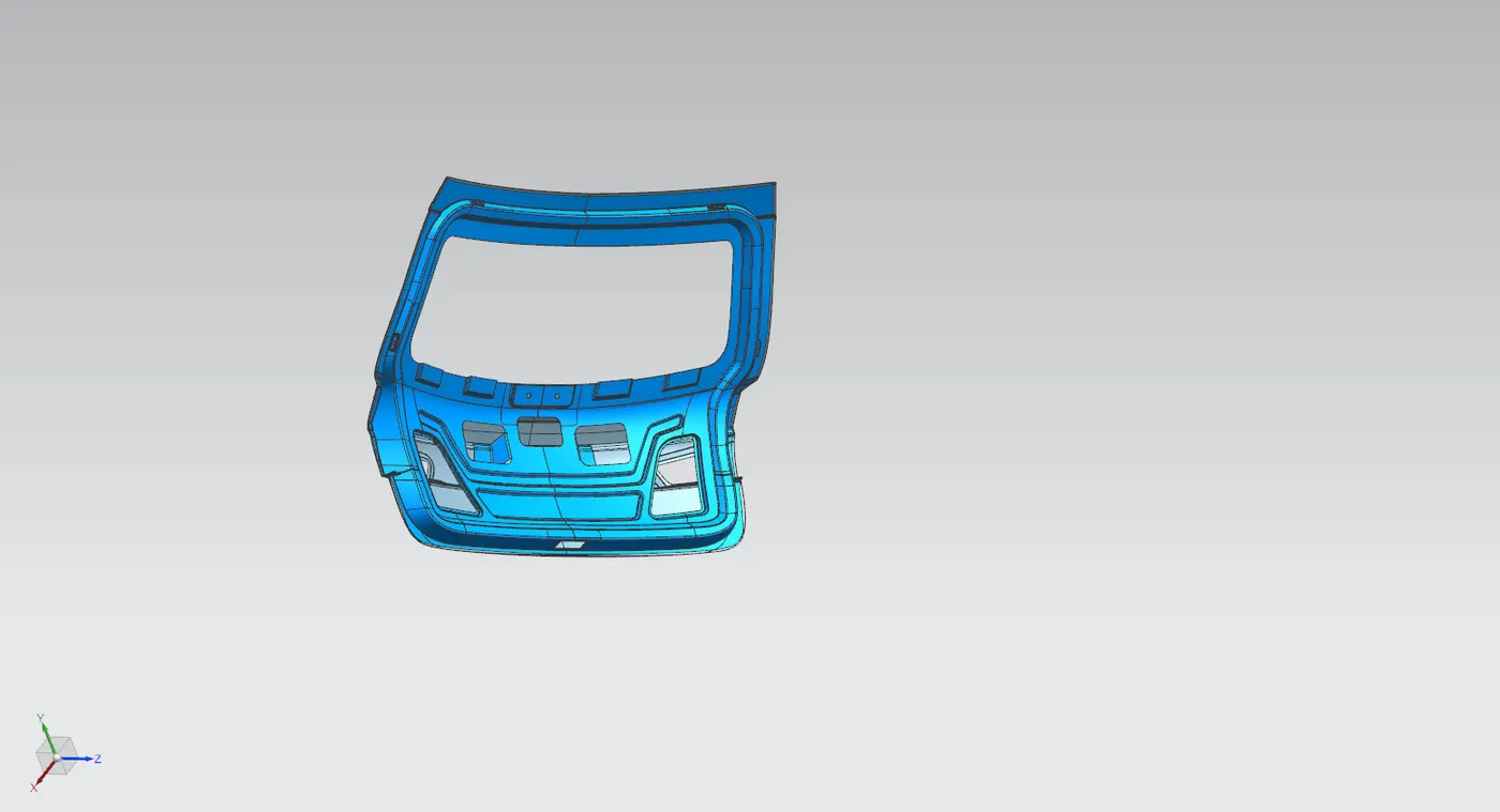
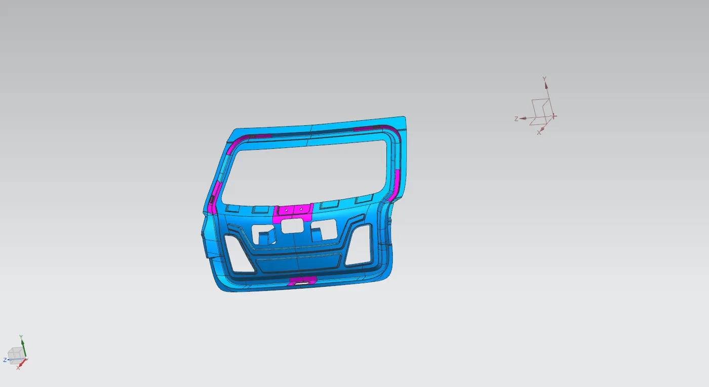
Final Design
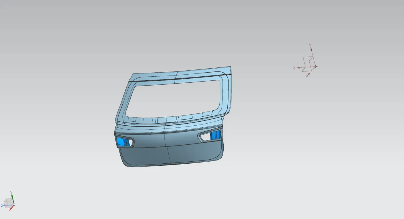
Draft analysis of the design
MANUFACTURING TECHNIQUES
Metal Stamping Process
It is the manufacturing process where flat metal sheets are converted to specific shapes through a number of metal forming techniques like bending, blanking, punching etc.
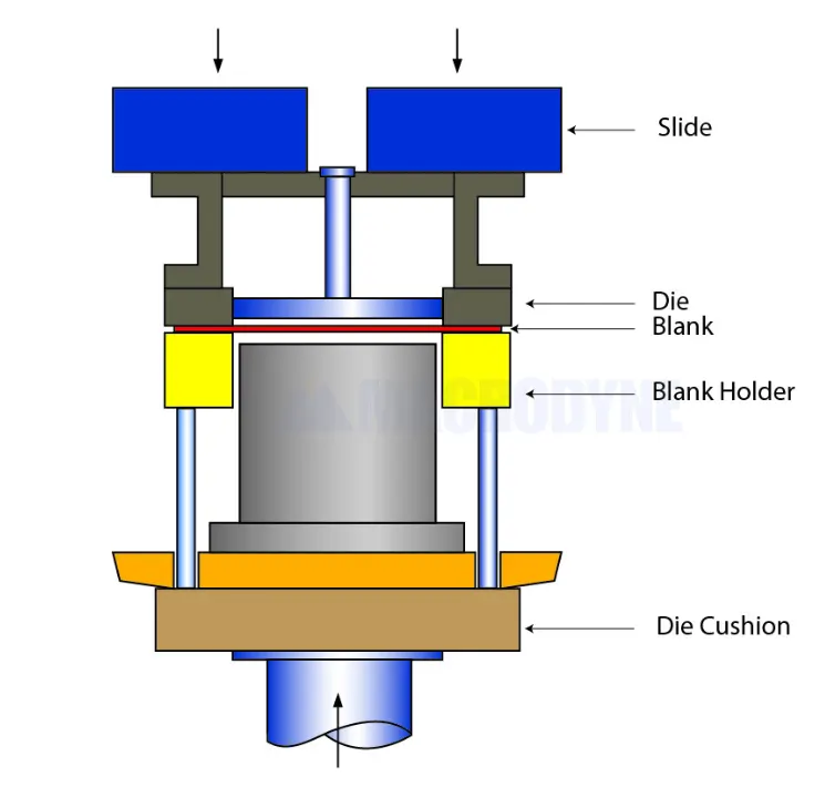
It involves placing the flat sheet metal blank into a stamping press. Using a tool and die surface form the metal into desired shape. There are several types of metal stamping methods like progressive die stamping, fourslide stamping, short run stamping but for manufacturing of automotive components mostly deep drawn stamping is utilized.
Deep Draw Stamping
In this method a sheet metal blank is pulled through the die via a punch, which results in required shape. This is called "deep drawing" when the depth of the drawn part exceeds it's diameter. This simple and cost effective method to manufacture seamless components thus widely used in automotive industry.
Hemming
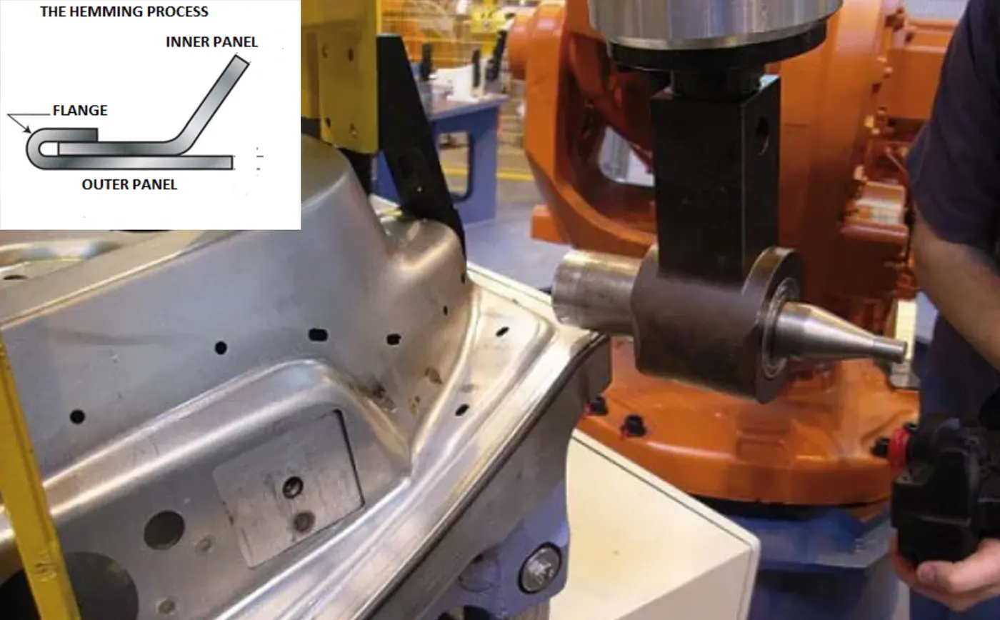
Hemming process is used in automotive industry to obtain parts with superior quality after the components are joined together. Commonly used to join together inner and outer panels of closure components such as doors, tailgates and hoods. Hemming is done by folding or bending of a flange of the outer panel over the inner panel to create a seal.
Hemming can be done by either tabletop hemming method where it is suitable for small parts at high production rates or roller hemming methods where the rollers can be integrated to industrial robots to make a progressive hems along components.
Mastic Sealants
Mastic sealants are used to bond the inner and outer panels by using a type of synthetic rubber sealant. Once the sealant cures it hardens thus providing strength to the parts it adheres to. They help to eliminate flexing in panels and provides improvements in NVH levels.
Welding
Welding is one of the major manufacturing process involved in automobile sector as the major components in them being metal. There are several methods used for different metals and for desired outcomes, but the major welding process involved during production is resistance spot welding. Others include MIG welding, TIG welding, Laser beam welding.
Resistance Spot Welding
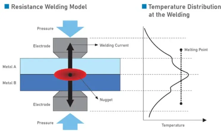
In this technique two metal sheets are pressed in between copper electrodes. An electric current passes through the points of contact which heats up and melts the metal thus joining them. This method is widely used as it produces clean and smooth welds, moreover the process is simple and easy to automate through a production line. This makes it cost effective in the long run.
CONCLUSION
A complete assembly of back door is done in NX CAD using provided skin data and other design consideration in mind. Draft analysis is done for the proposed design confirming the manufacturability.