Hood design-Week 2
HOOD DESIGN
AIM
To design a complete assembly of an automobile hood comprising of the hood outer panel, inner panel, latch, hinges along with required reinforcements by adhering to provided design parameters.
OBJECTIVE
1. To design the hood outer panel, hood inner panel and any necessary reinforcements required according to the master section and skin data.
2. To create an assembly of the hood using the designed parts along with latch and hinges following the master section and design parameters.
3. To validate the assembly whether it fulfills the design criteria provided including mastic data, latch trajectory and clearances.
INTRODUCTION
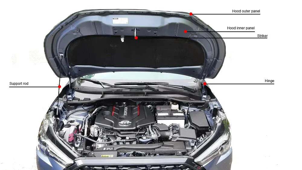
The bonnet or hood of an automobile is a closure component presented as a hinged part that acts as a cover over the engine compartment located at the front of the automobile. Hoods allow access to components within the engine bay for inspection and maintenance.
The hood consists of the following:
Hood outer panel : It is the outer visible part of the hood with a smooth surface finish. It is made by offsetting the styling surface ensuring it adheres to the proposed design by styling team. It makes a rigid structure which is held to the inner panel by hemming process along with mastic sealants.
Hood inner panel : It is the structure which provides mounting surfaces for the hinge assembly, striker, mounting points for strut. It acts as a reinforcement for the hood. They are designed in such a way that they are light weight yet provide necessary reinforcements as required.
Hinge assembly : Hinge assembly allows the opening and closing of the hood along the hinge axis. It is mounted on the inner panel on one end and to the engine bay at other end.
Latch & striker mechanism : The latch and striker mechanism allows the hood to be closed and opened upon requirement. The striker is usually placed on the hood inner panel and the latch is placed inside engine bay. When the hood is closed the striker is pressed against the latching mechanism and the latch slides over the hook and springs help them to stay in place.
While designing the hood of an automobile there are design parameters provided by the styling team along with that there are certain design considerations that needs to be taken into consideration:
1. Pedestrian and occupant safety. (Wrap around distance, Hood opening angle, NVH)
2. Manufacturability of the components. (Mastic points, reinforcements, clearances)
3. Styling of the final product.
DESIGN OF HOOD IN NX CAD
Steps involved in designing of the hood assembly:
Obtain design inputs and design parameters.
The design data should be obtained and analyzed before designing the new parts. Here the following data has been collected :
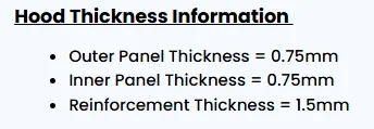
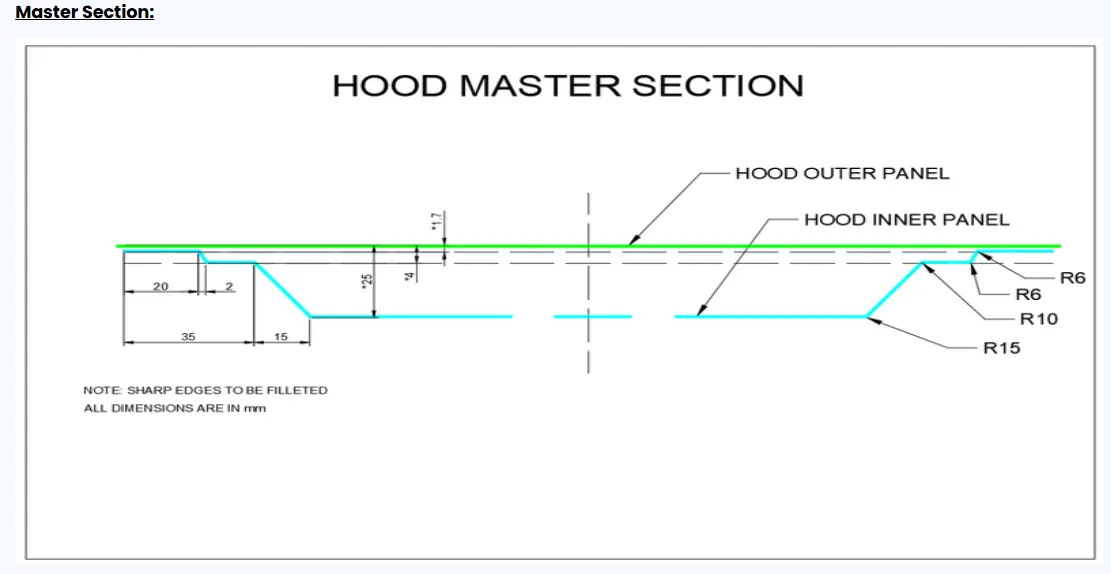
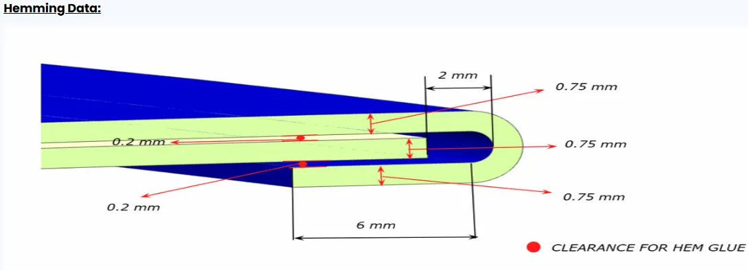
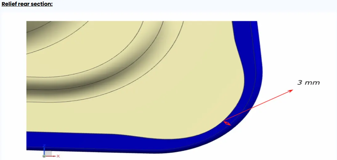
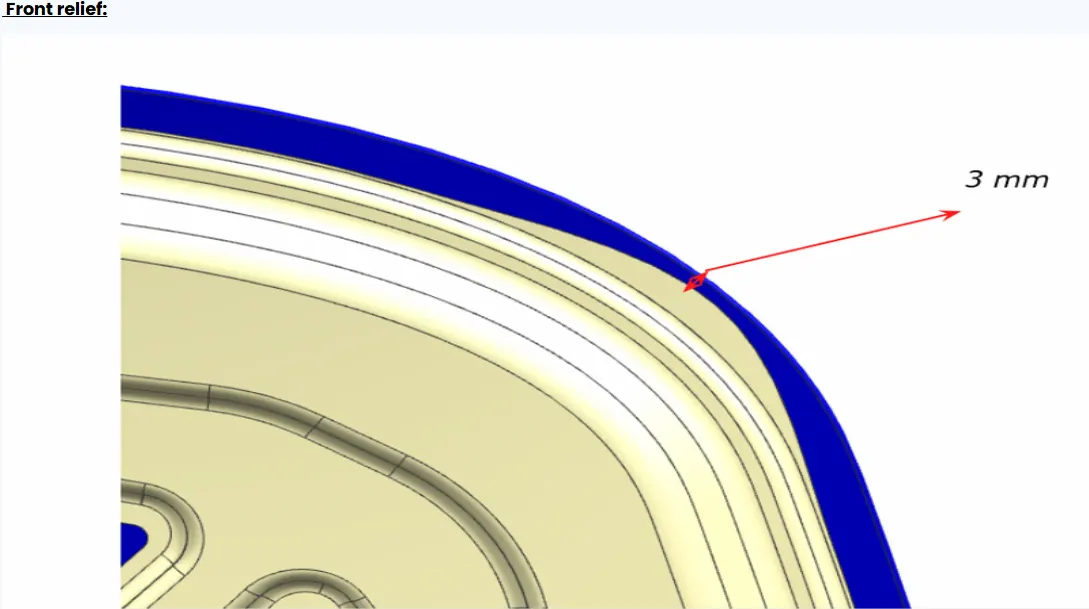
Along with these parameters parts of hinge assembly, striker and hood skin data is also collected. These parts are imported into NX by creating a new assembly and adding these components.
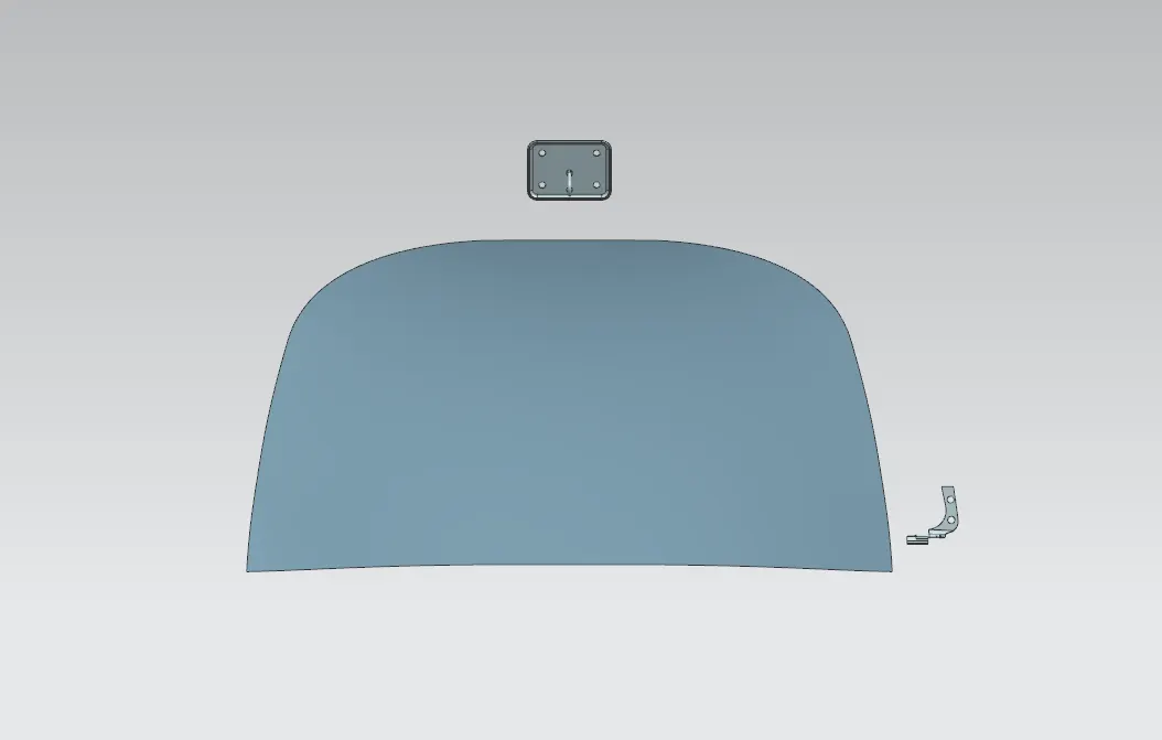
Design of Hood inner panel
Design the inner panel using the skin data by utilizing the surface using the wave geometry linker. Using this create a new part inside the assembly as hood inner panel.
To make work flow easier we trim the working surface/sheet in half using trim sheet operation.
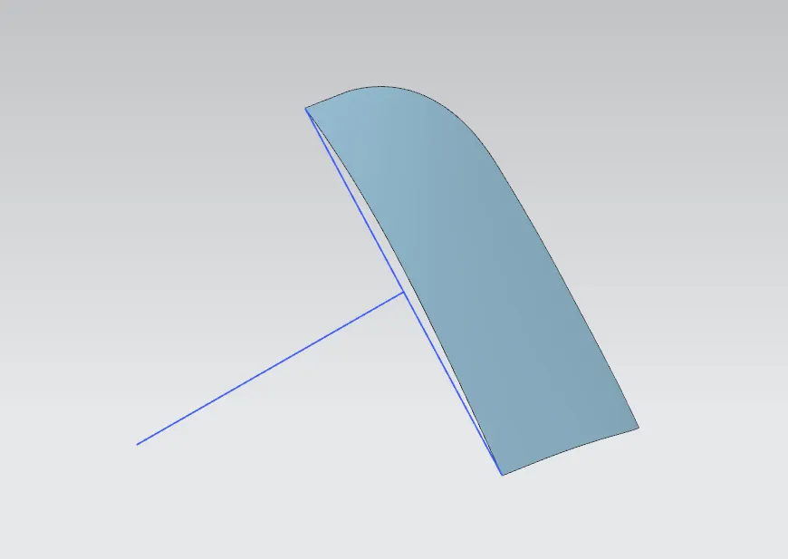
Tooling direction
Now the Tooling direction is specified in the part using sketch as shown in figure. The panel is made through stamping so, tooling direction is the direction about which the tool advances towards the die (It should have a minimum draft angle of 7 degree)
Creating Flanges
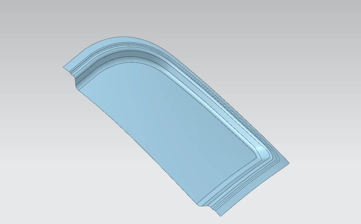
Now using this surface as reference we create the flanges inside the inner panel. Using "offset surface" operation the surface is off-set and trimmed according to the hood master section. 3 such flanges are made as in the master section. These flanges are then connected using "through curves" operation. After that the sharp edges are eliminated using "face blend" operation.
Creating Emboss
Before creating emboss it is important to get measurements of the striker and hinge assembly as there should be enough clearance for these parts to mount onto the outer surface of the inner panel. Using "Measure" tool from "Analysis" tab the measurements are obtained for the parts.
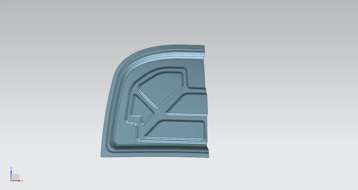
Now keeping these data in consideration the first level of emboss is done. The sketch is made on XZ plane with origin set on the point on the panel itself. This sketch is projected onto the surface using "Project curve" command. After this "Emboss" command is used to create the emboss with a depth of 9mm for this particular design making sure to make tooling direction is set to the one created and draft angle of 10 degree. "Edge blend" is used to remove sharp edges and unify it.
Followed by this operation second level of emboss is done similar way with different sketch at a depth of 9.5mm and draft angle of 12 degree. Leaving behind a gap of 5mm for the mastic sealant (according to master section)
Creating cutouts with mastic points
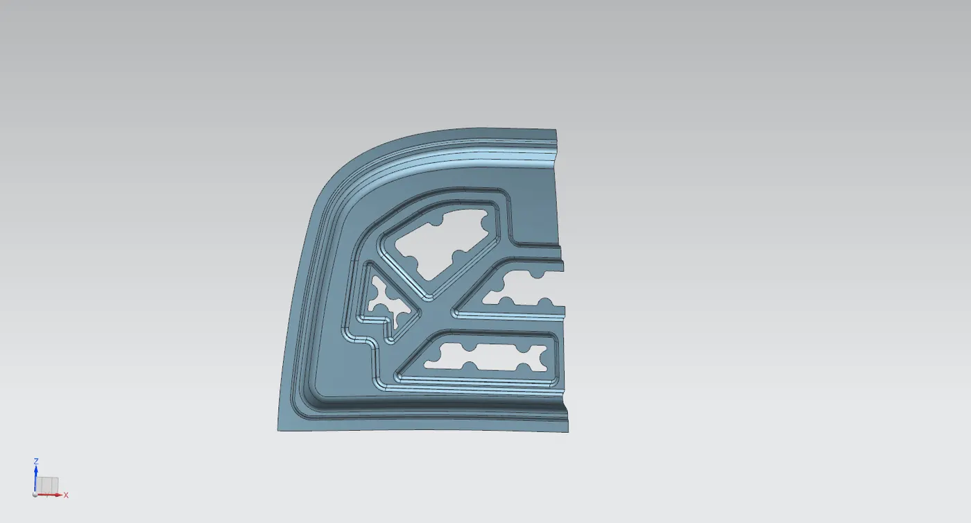
Cut outs are provided in the second level of emboss, It is done so as to improve pedestrian safety and also it reduces the weight of the panel. Mastic points are added for the sealant. Mastic region is the area around a mastic point. Here mastic regions are of 25mm diameter.
Sketches are made in the desired shape for the cutouts with regions allocated for mastic points. These sketches are projected to the surface and trimmed off to provide required cutouts in the sheet metal.
Creating Hinge Mounts and Assembly of Hinges
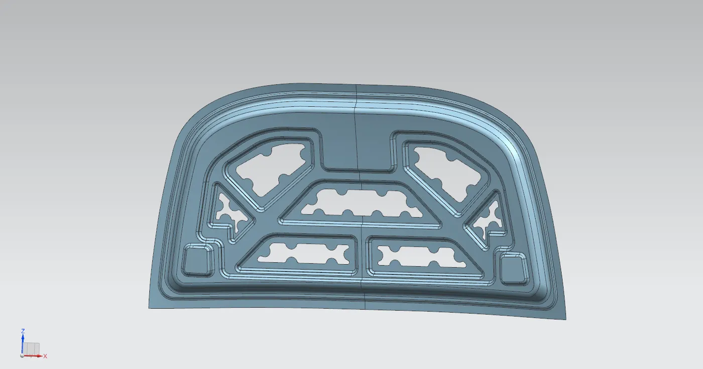
For creating hinge mounts the sketch is drawn on the ZX plane and projected onto the surface and using this sketch the surface is embossed in the tooling direction to create the mount. To obtain a flat surface for mounting the end cap is changed to a datum plane and depth is specified using an offset value.
After this the whole part is mirrored to make a complete panel. The mirrored parts are unified using "Sew" command.
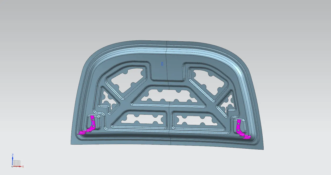
After this the hinge assembly is constrained to the hood inner panel using assembly constrains. The back face of hinge is provided with a touch constrain to the mounting surface. The hinge axis is given a parallel constrain with the X-axis. The component is moved and oriented. The hinge assembly is mirrored to get the hinge on other side.
Creating Striker mount and assembly of striker
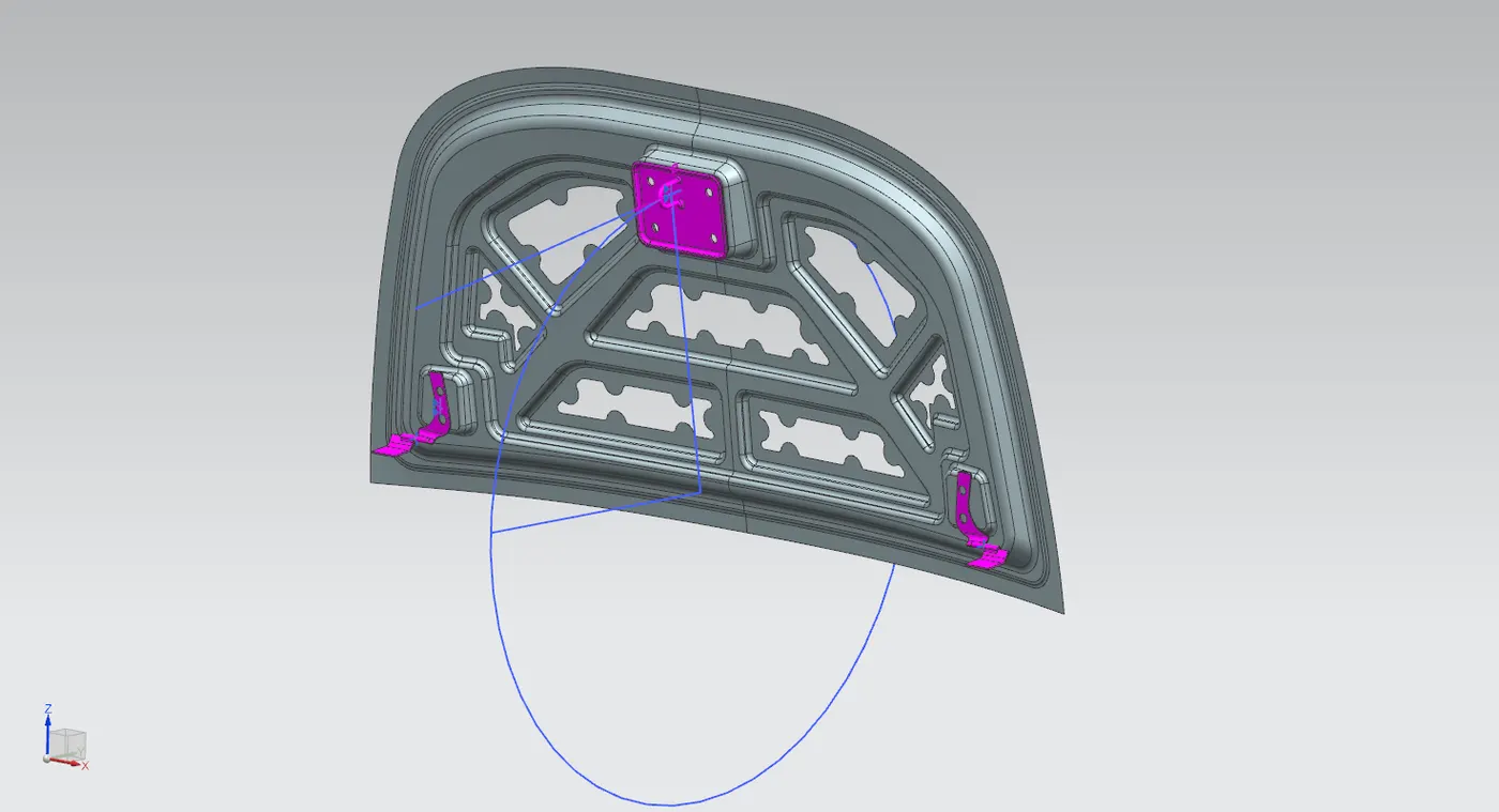
Striker mount can be created similar to hinge mount, but before that the latch trajectory needs to be specified in order to achieve an accurate position for the striker on the inner panel. A hinge axis is created passing through the two hinges by extracting the curves in the hinge using "wave geometry linker" and by using the center point axis is drawn.
Latch Trajectory
Latch trajectory is obtained by creating a circle with it's center at the middle of hinge axis. This circle shows the trajectory followed by the striker when the hood is opened or closed. The striker should be mounted in such a way that the tangent to this circle and striker are aligned in order to ensure proper closing with the latch.
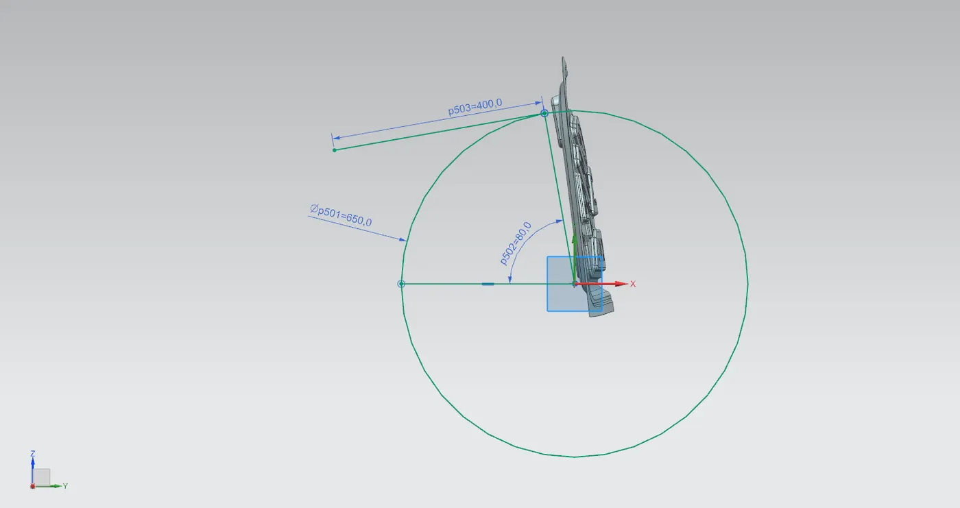
Now in assembly the striker can be constrained to the obtained trajectory. On the striker model a datum plane is created along its central axis (YZ plane) and a normal is drawn through the C-hook along the point of intersection of the latch and striker.
The starting point of normal is given a touch constrain with the intersection point of tangent on circle. Again the normal is given touch constrain to the tangent line and the central datum plane constrained to datum plane along the trajectory sketch is made. Making sure to orient the faces of striker correctly.
From the desired point of striker - extract the striker's rear face. "Extend Sheet" command used to extend the curve along 8 mm to avoid loss during trimming. Now using this surface a "law extension" is created along the vector of tooling direction (Positive draft). Now this parts are sewed together followed by a "Trim and extend" command to remove additional material. "Edge blend" is applied to remove sharp edges.
Thickening of inner panel
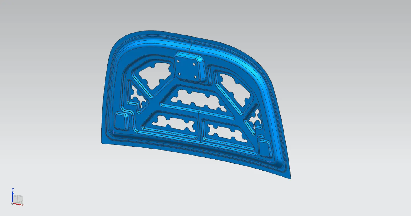
Before thickening of the panel the sharp edges are taken down by using a "bridge curve" command to create a smoother edge and trim off the excess. Now offset the outer curve onto the surface by 2mm (To provide clearance between hem of the outer panel) and trim the excess region . After that "Thicken" operation is used to give the surface a thickness of 0.75mm.
Creating Hood outer panel
The skin data is used to create the outer panel. The outer panel is trimmed in half for ease of workflow.
Similar to inner panel the edges are made rounded by using "bridge curve" command by the same value used for inner panel and the excess is trimmed off.
This surface is offset to a value of 2.65 mm downwards to create a flange as in master section. The new surface is offset on the face for a value of 6mm to create the width of flange and excess regions are trimmed off.
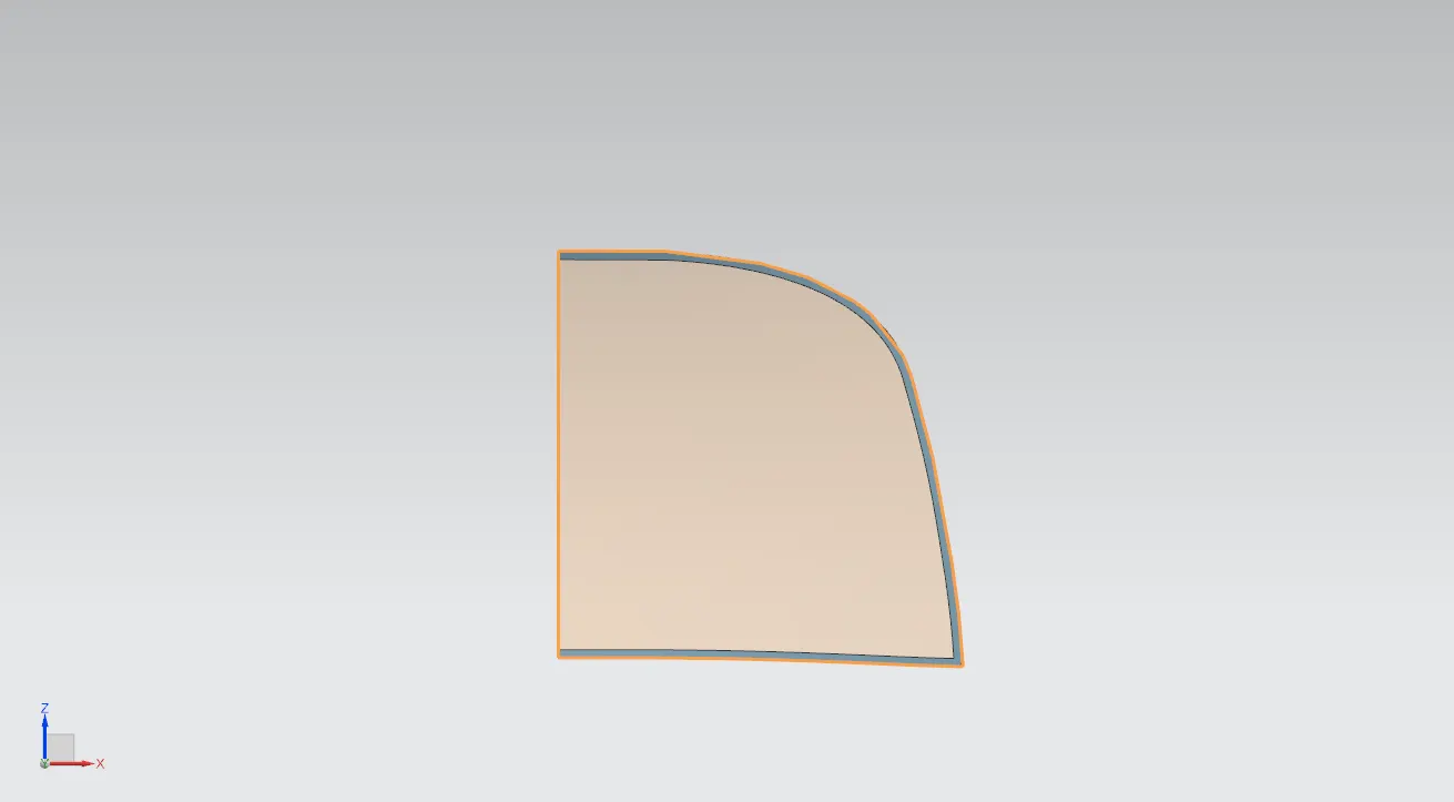
Now using this surface a new law extension is made to create a connection between the two surfaces. A 3 face blend is used to create the hem by using the upper surface, the lower flange and the law extension surface.
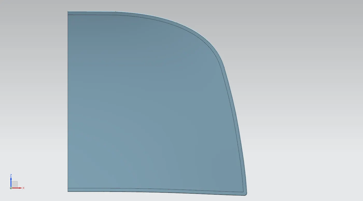
Hem reliefs are created to reduce stress concentrations on the surface as in the design parameter.
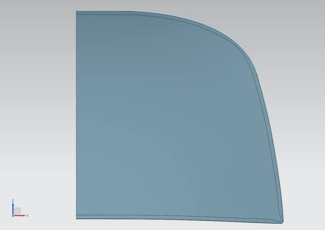
The whole part is mirrored to obtain a full hood outer panel. The panel is then thickened using a thickness of 0.75mm.
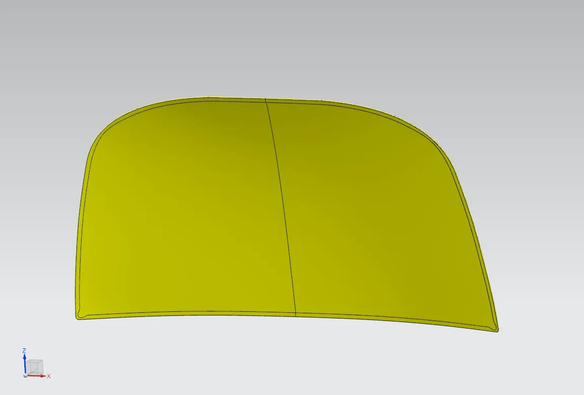
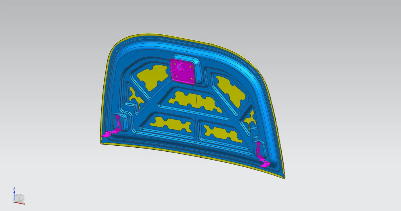
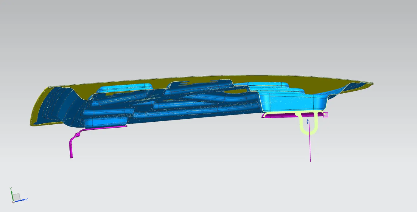
Thus the assembly is completed.
Manufacturing Processes involved
Deep Drawing
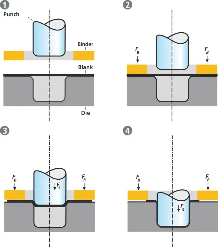
Deep drawing is one of the most commonly used forming techniques in sheet metals. They are widely used in automotive industry as these achieve parts with good mechanical properties at a reduced operation cost and a much faster production rate.
The deep drawing assembly primarily consist of 3 components a punch, a die and a clamping mechanism. Here the sheet metal blank is drawn into the die by the punch. When the depth of the part produced exceeds the diameter and hence considered deep drawing here the result is obtained through redrawing the part through several dies.
Hemming
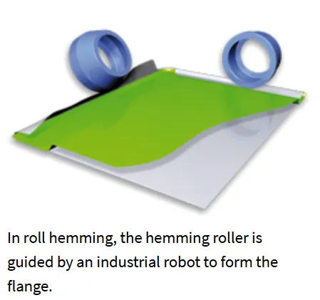
Hemming process is used in automotive industry to obtain parts with superior quality after the components are joined together. Commonly used to join together inner and outer panels of closure components such as doors, tailgates and hoods. Hemming is done by folding or bending of a flange of the outer panel over the inner panel to create a seal.
Hemming can be done by either tabletop hemming method where it is suitable for small parts at high production rates or roller hemming method where the rollers can be integrated to industrial robots to make progressive hems along components.
Mastic Sealants
They are a type of synthetic rubber sealant used to bond the outer panel and inner panel together. Once the sealant is cured it reduces panel distortion. It also helps to reduce vehicle NVH.
Conclusion
A complete assembly of hood including it's outer panel, inner panel, hinge assembly and striker mechanism has been designed using NX CAD. The design also includes required reinforcements and relieves as required for the manufacturing processes required.