Fender Design
FENDER DESIGN
AIM
To design a front fender with Drip, A-pillar, bumper, sill and baffle mountings for an automobile using Seimens NX.
OBJECTIVE
1.To design front fender using provided skin data and master section for drip mounting.
2.To design A-pillar, bumper, sill and baffle mounts for the fender with design considerations.
INTRODUCTION
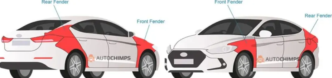
Fender is a panel which covers the front and rear wheel of a vehicle. They provide protection to the engine and components inside the vehicle from external elements like dirt, rocks and mud being flung-off from the rotating tires. They also prevent these projectiles from getting thrown outside towards pedestrians. The fender also provides an aesthetic purpose since it is visible from the outside it contributes towards the overall visual appeal and design of the vehicle.
Fenders can be classified into two types : Full and Half bumper type.
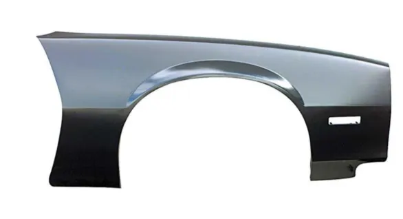
Full Bumper Type
As the name suggests the full bumper type fender extends from the bumper all the way back towards the A-pillar. This is considered a traditional design and is not used nowadays. The relatively large design resulted in difficulty to manufacture and produced a lot more scrap metal. It was not economically feasible.
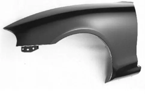
Half Bumper Type
This is the more modern approach on fender design as it significantly reduces the size of blank and uses less material thus reducing wastage and increasing cost effectiveness. They are relatively smaller in size.
DESIGN OF FENDER IN SIEMENS NX
The steps involved in designing the fender are as follows:
Obtain Design inputs and parameters
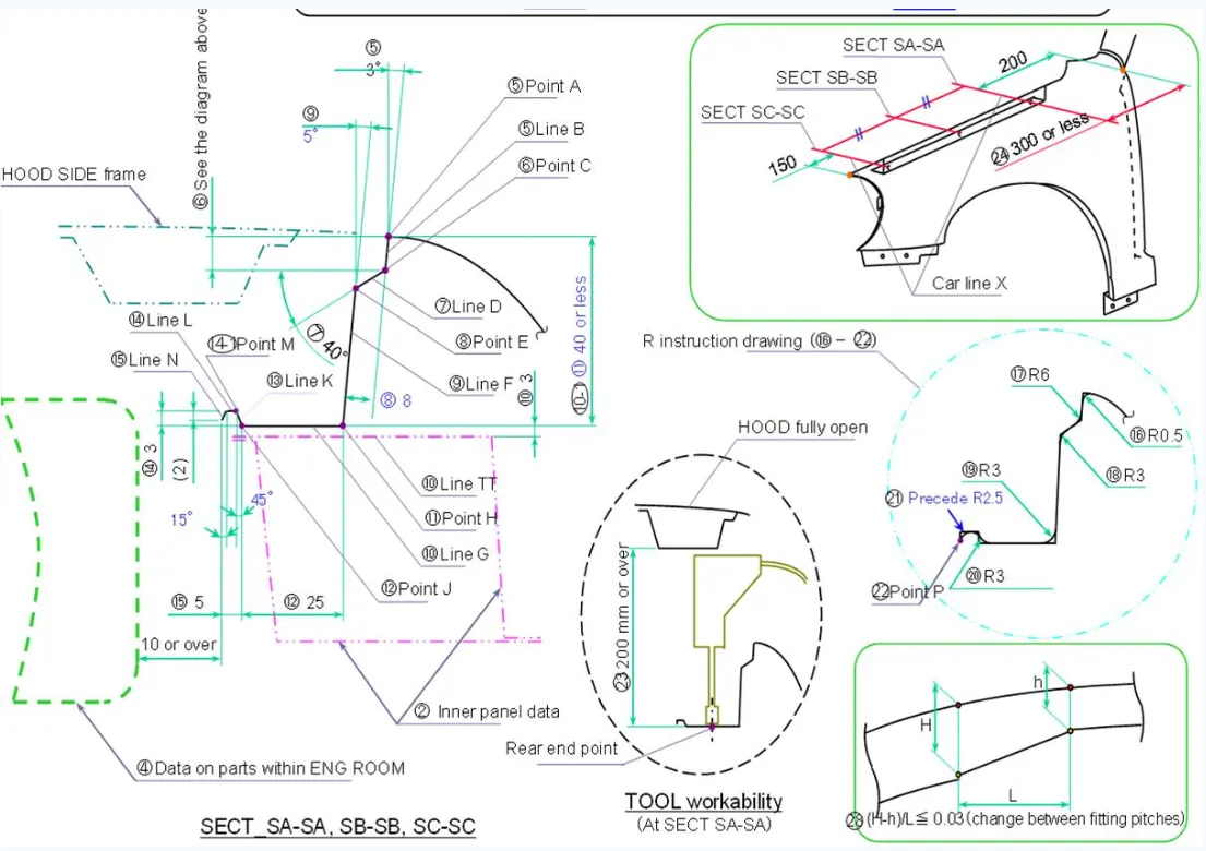
The given master section and skin data is studied before the designing of complete fender to identify the locations and considerations for various mounts throughout. The data given for the project are:
1. Master section for drip mounting.
2. Skin data of the front fender.
Design of drip mounting region
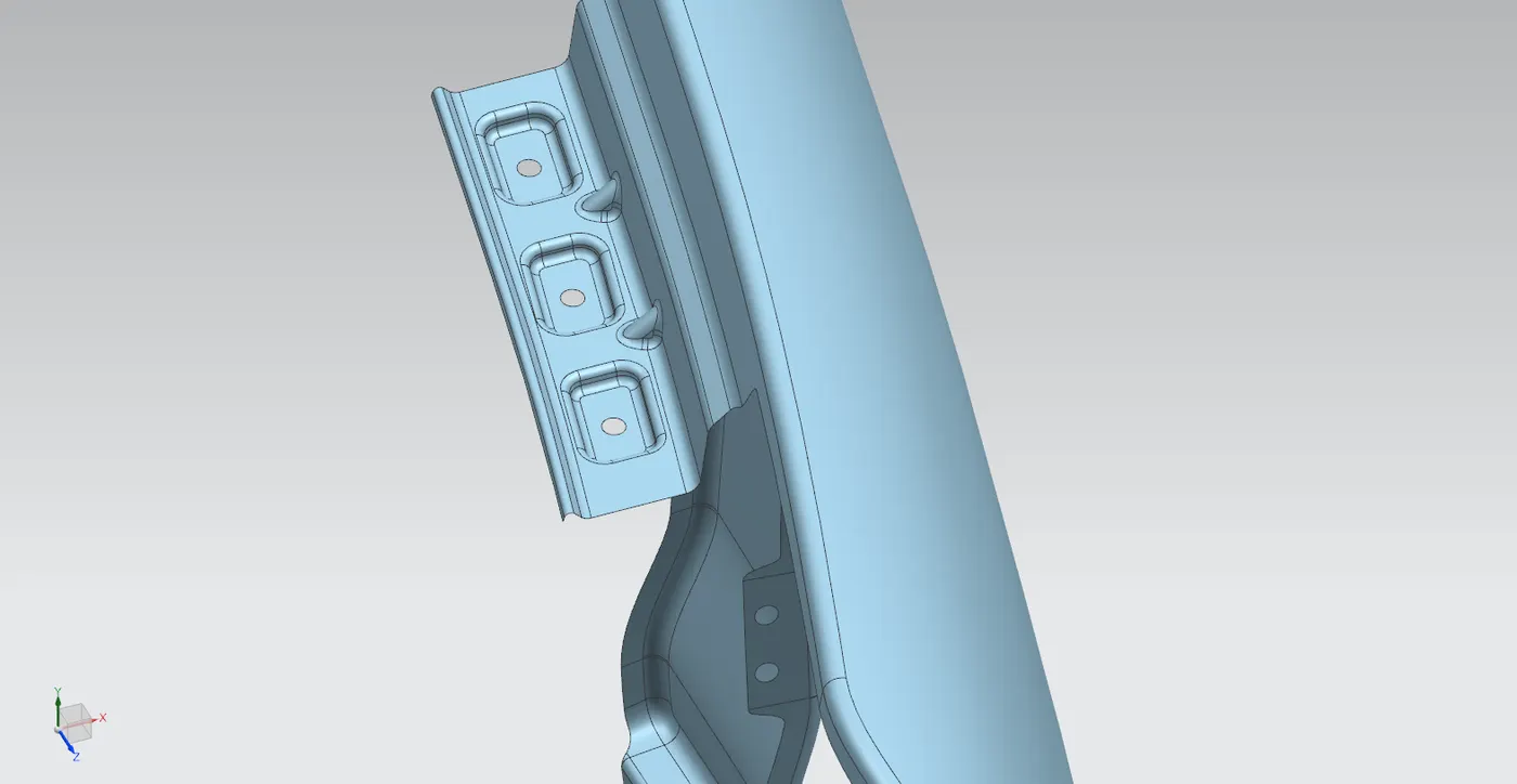
This region is the area where the fender is connected to the engine bay. This is designed in such a way that there should be proper gap and flushness between the hood and fender and the mounting region should not be visible from outside.
Conditions for the bumper mounting region is specified in the master section. The important parameter being the distances from bumper mounting (Should be 150mm) and A-pillar mounting (300 mm or less).
For the mounting region 3 holes (5mm) are provided over embossed surface for mounting along the drip region, Since the region is relatively large ribs have been added to ensure structural rigidity. The flange has been created according to the master section. The surface has been trimmed to size and extended using "law extension" command from skin data. Fillets and bridge curves are used to avoid sharp corners in the sheet metal. Embossing is done for the mounting regions followed by blends to eliminate sharp edges.
Design of A-pillar mounting region
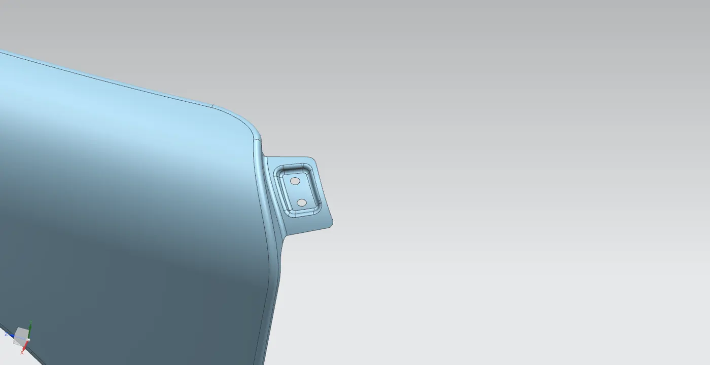
For this mounting points no specific data is provided but from master section we can observe the location of the mount. The mounting has been made by extending the sheet from the existing skin data (by 50mm) at the required location. The sketch for emboss and mounting holes are constructed by assigning a datum plane with inference to the mounting surface and later projecting the sketch to the sheet metal. Embossed regions are made similar to that of drip mounting region, holes are provided with 5mm.
The edges are given blend to avoid sharp edges. The excess regions are trimmed off followed by "bridge curve" command to remove sharp outer edges.
Design of Sill mounting region
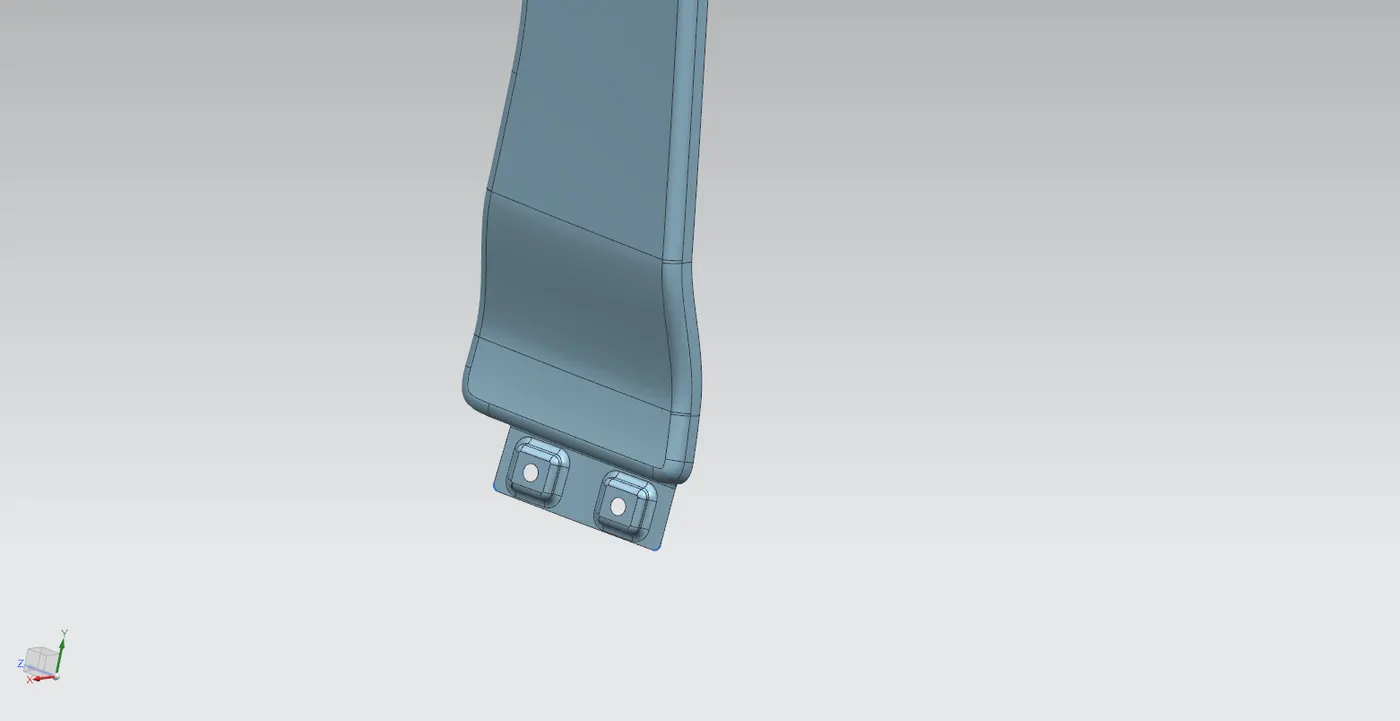
From the master section we can see that the sill mounting region is almost perpendicular to the drip region but located at the bottom of the fender. In similar way to that was used to design the A-pillar mounting region the sill mounting region is designed. Here two separate embossed surfaces are provided for mounting holes (5mm). The surface was extended and required sketch made on datum plane with inference to the mounting surface and later projecting the sketch to the sheet metal. Blends and bridge curves are used to avoid sharp corners.
Design of Bumper mounting region
The bumper mounting region is generated by extending the required region from the skin data using "law extension" command and required sketch for the mounting is made on a datum plane inferred from the extended surface. The mounting regions are embossed with holes of 5mm trimmed from it. Again blends and bridge curves used to smoothen out edges.
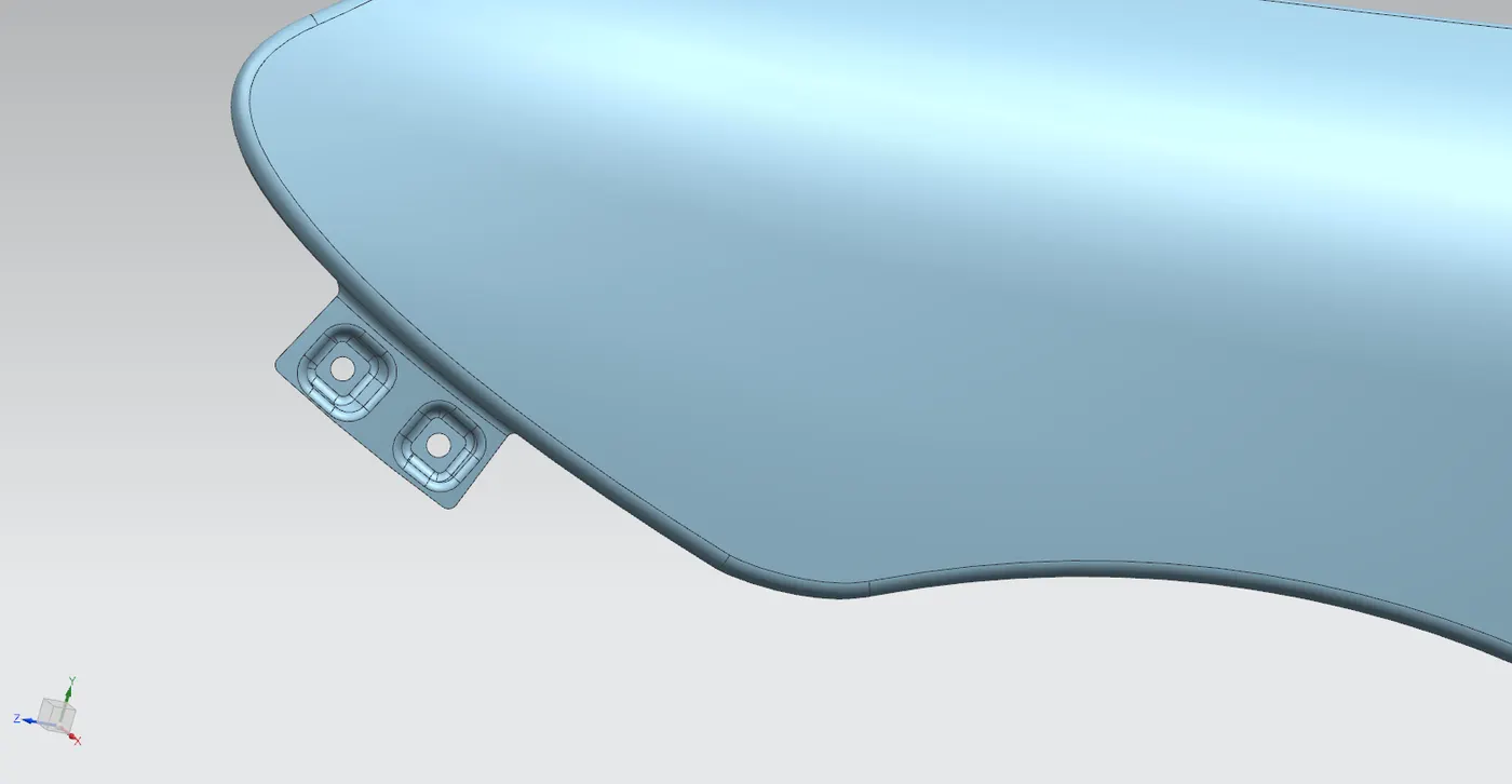
Design of Baffle mounting region
Baffle or splash mounting region is where a plastic component (baffle) is mounted with help of trim clips around the wheel well. Here there are 3 separate regions where mounting holes are provided. Three separate sketches are made based on the surface to be trimmed for the holes. The holes are of 5mm similar to that of others. The sketches are projected and trimmed to create the mounting.
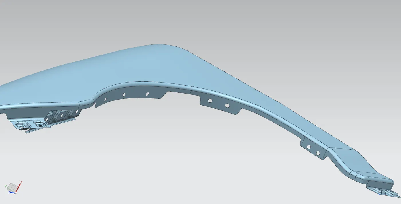
After the completion of all the mounting points thickness of .75mm is given to the surface using "thicken" command.
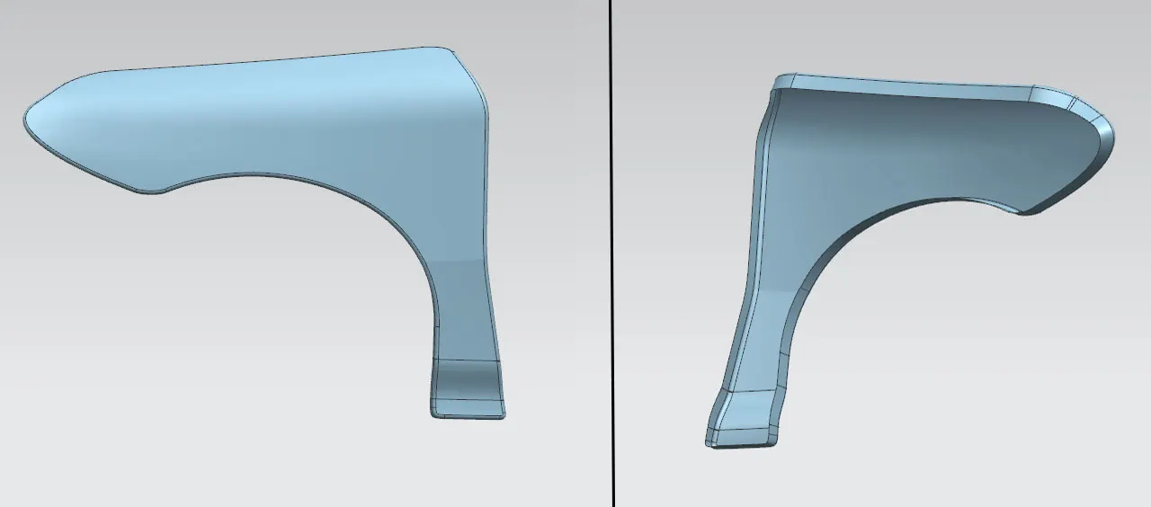
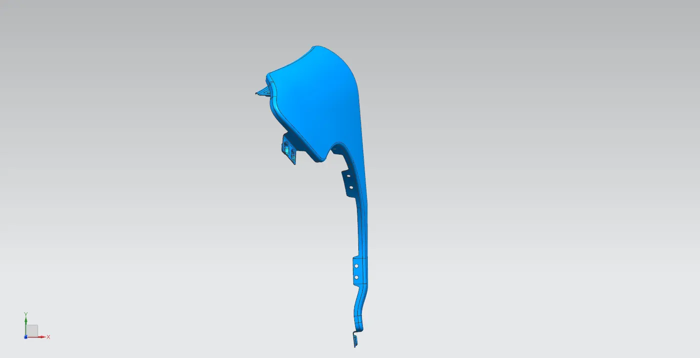
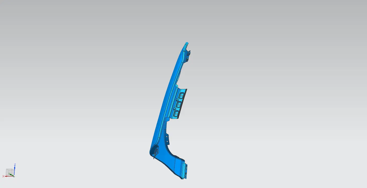
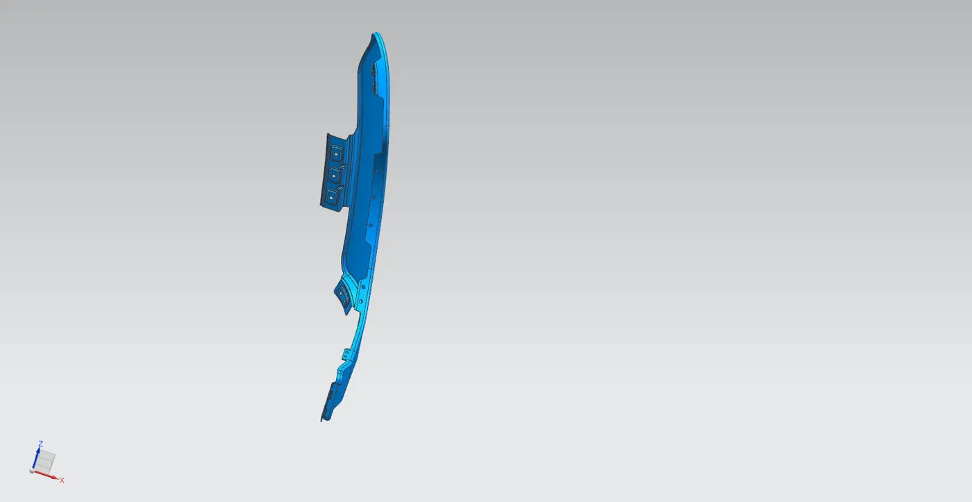
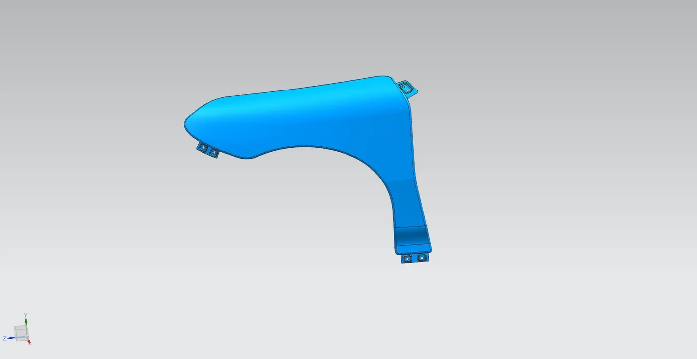
The final design in various orientations are shown below:
MANUFACTURING PROCESS INVOLVED
Metal Stamping Process
Metal stamping is the manufacturing process where flat metal sheets are converted to specific shapes through a number of metal forming techniques like bending, blanking, punching etc.
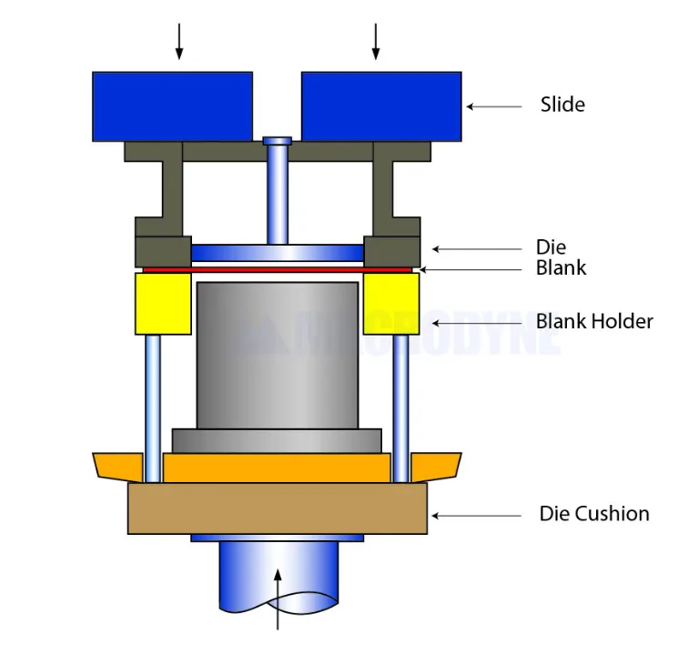
It involves placing the flat sheet metal in blank form into a stamping press. using a tool and die surface form the metal into desired shape. There are several types of metal stamping methods like progressive die stamping, fourslide stamping, short run stamping but for the manufacturing of automotive components mostly deep draw stamping is utilized.
Deep Draw Stamping
This method involves pulling a sheet metal blank through the die via a punch, which results in required shape. This is called "deep drawing" when the depth of the drawn part exceeds it's diameter. This a simple and cost effective method to manufacture seamless components thus widely used in automotive industry.
CONCLUSION
A complete design of the front fender is created including Drip, A-pillar, bumper, sill and baffle mounting regions using the provided skin data and master section using Siemens NX.