Week 9 - Challenge 2 - Switch Bezel Design
AIM: To Create the Switch Bezel Plastic component through the given Class-A surface by taking the Thickness of the component to be 2.5 mm. To begin with, the tooling axis for the given Class-A Surface should be created meeting the requirements of the draft angle and at the end perform the Draft analysis on the model.
OBJECTIVE:
- Checking continuity of class A surface.
- Deciding feasible tooling direction & creating tooling axis.
- Performing draft analysis on class A surface.
- Creating class B surface from given class A surface.
- Creating class C surface to join A & B class surface.
- Creating solid feature by using closed surface.
- Performing draft analysis on final plastic component.
NOTE:
- Ensure Proper Tree Structure
- Geometrical sets should have a proper name based on the sketches present inside of it
- All the sketches should be created under the Geometrical set
- Use the Close Surface feature to make a solid body from the surface.
- Publications: Use the publication option and publish the below
- Tooling Axis
- Class A, B, and C surface
PROCEDURE:
We'll receive Class-A surface as our input to create a solid part by creating the Class-B and C surfaces.
We'll check Class-A for any gaps or discontinuity in between the surfaces by visual check or by boundary command if there will be any connexity error so we have join Class-A by joining value of 0.003mm as shown below-
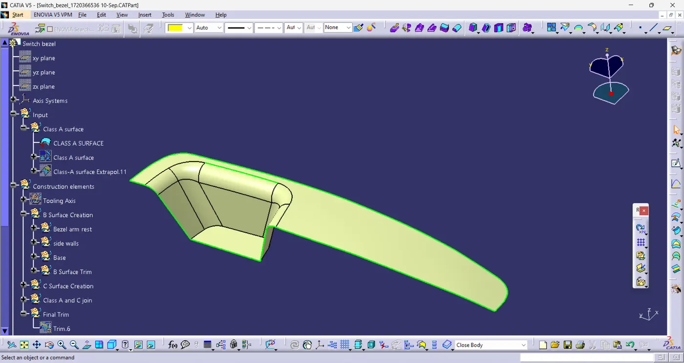
Correct Class-A surface-
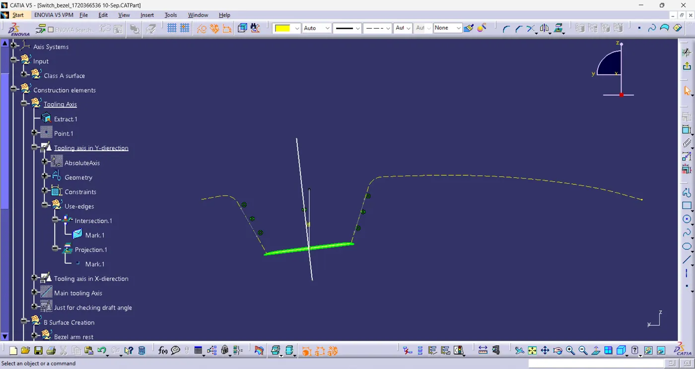
Creation of tooling axis-
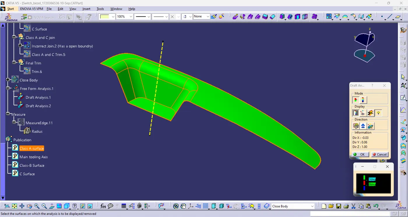
after creating the tooling axis we perform a Draft analysis of class A surface to check if class A has proper draft values along with the tooling axis-
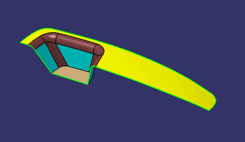
Class-B surface creation at off-set value of 2.5mm in order to create thickness and thickness should be uniform throughout the plastic part body by extracting surfaces from class-A, un-trimming and extrapolating the extracted surfaces and trimming them together-
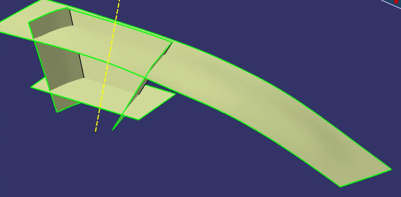
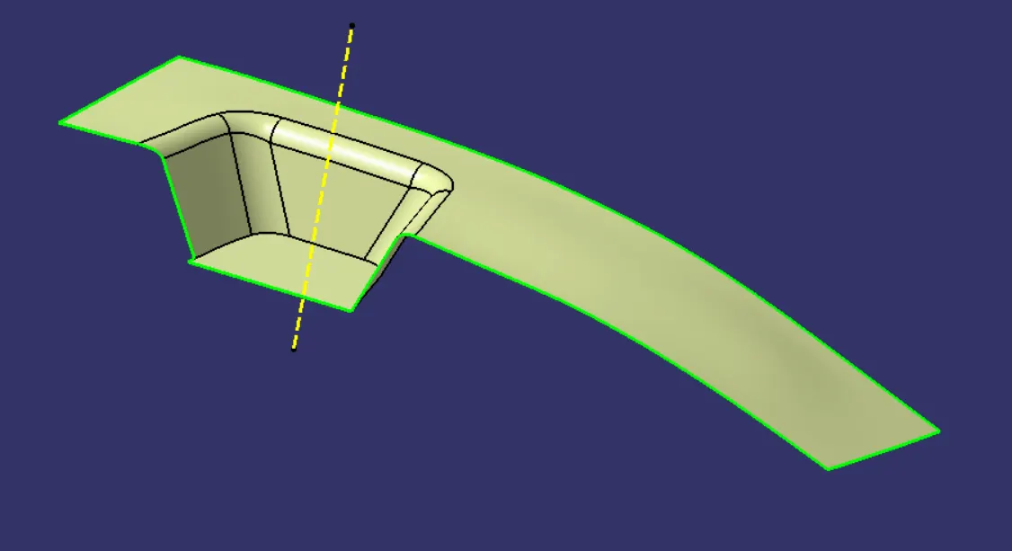
after trimming and adding fillets-
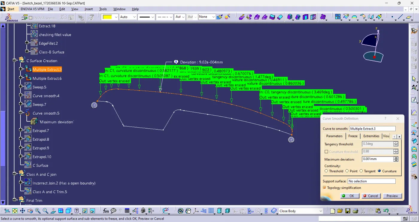
Class-C surface creation by creating boundaries of class-A in 2 parts and then we have smoothened the boundaries so that the small patches should not form and then sweeping them along the direction of the tooling axis after that we will join the class-A and C surfaces-
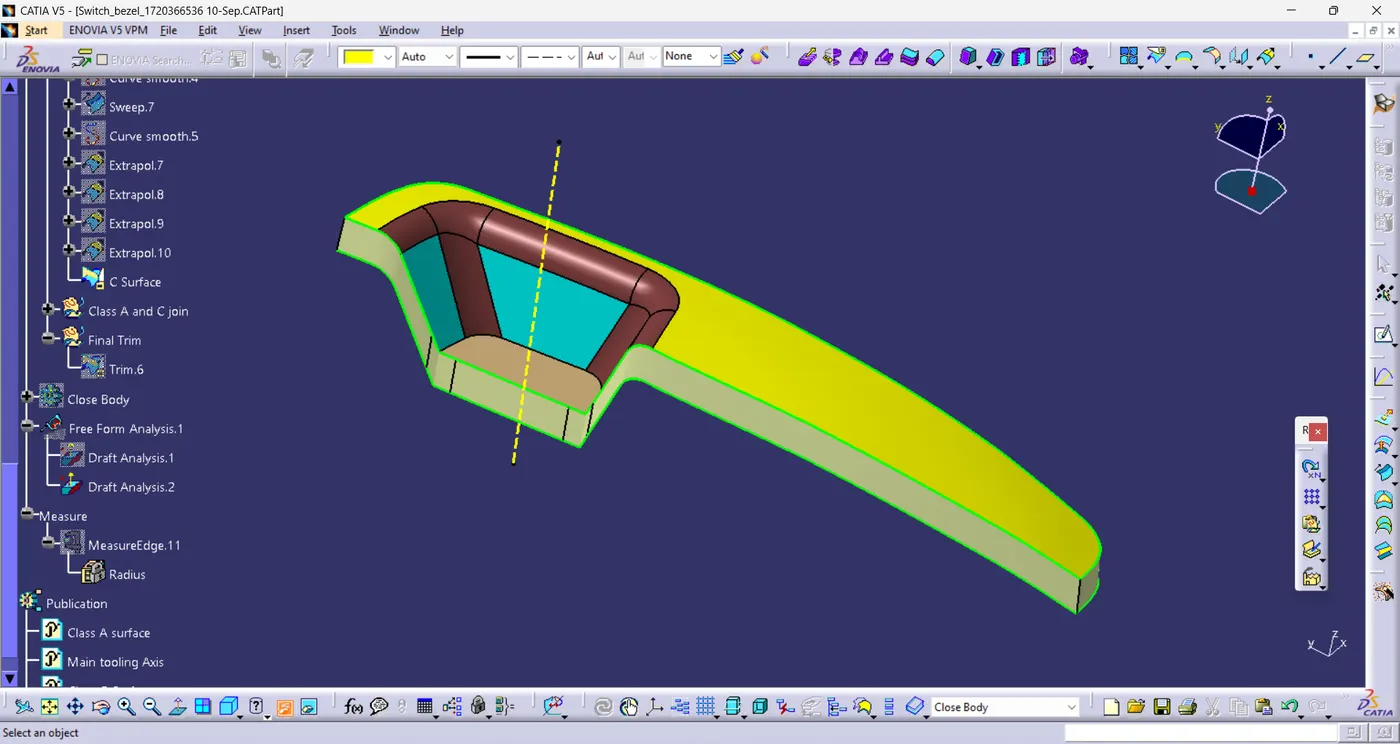
class A and C surface trimmed together-
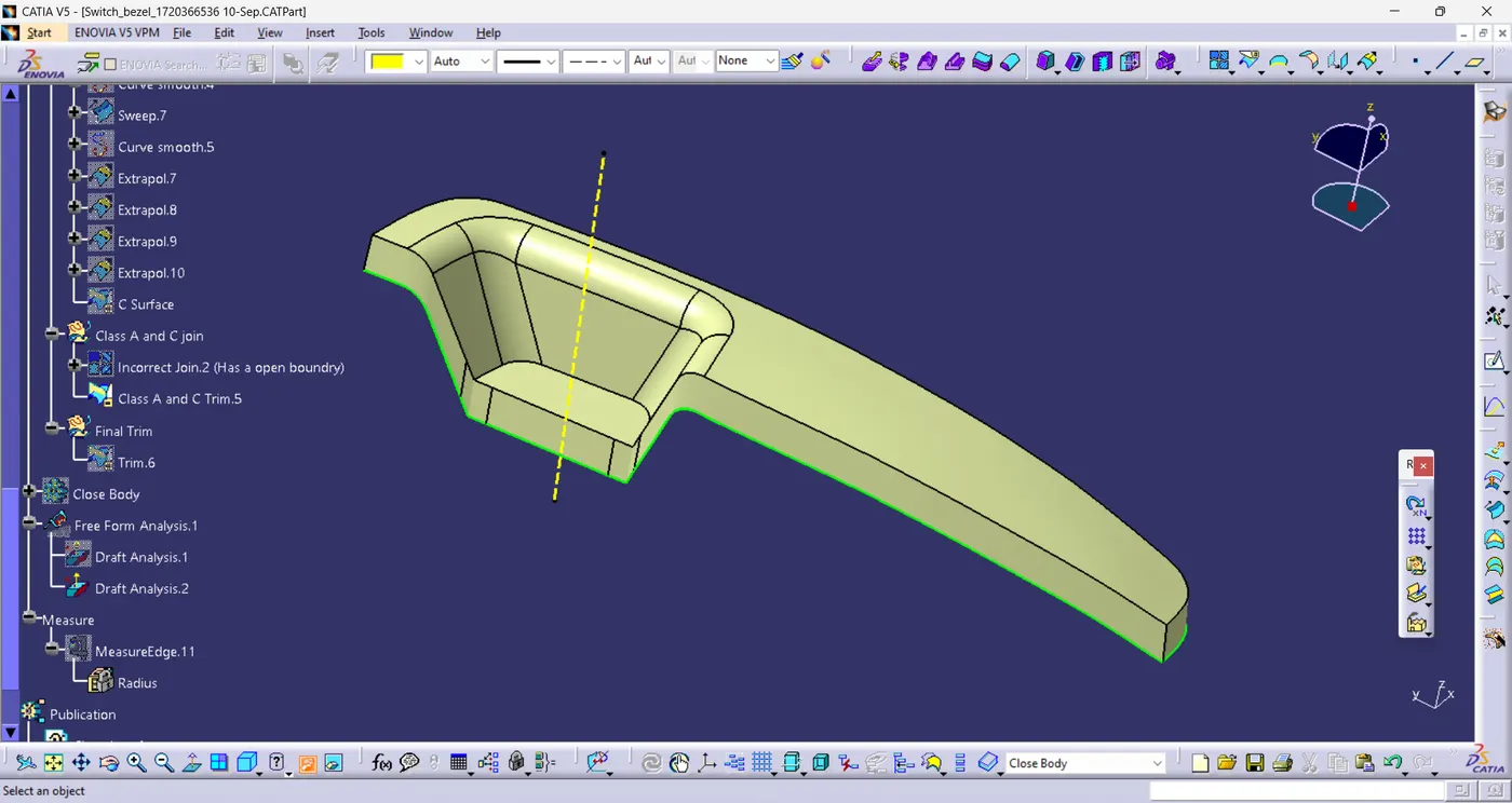
Final Trim-
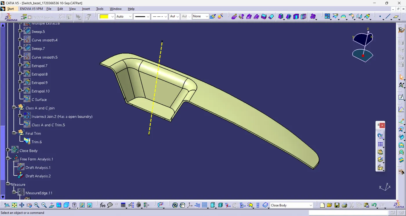
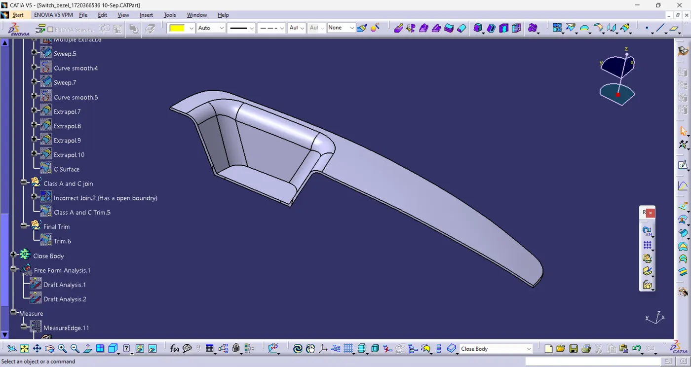
Will create a close body of the final trim using close body command in part workbench-
Draft analysis of the final solid body by providing proper color values for different draft values as shown-
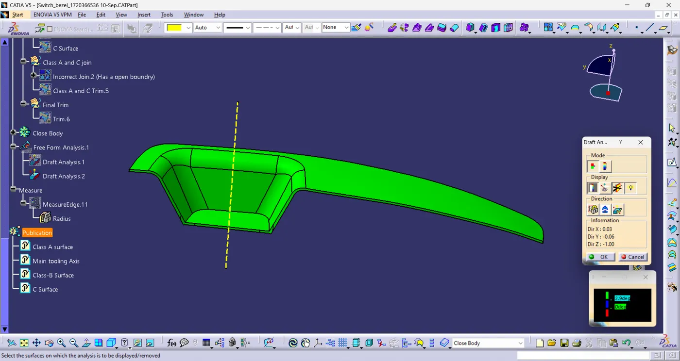
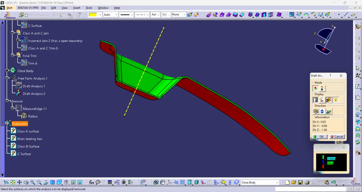
As we can see from the picture above the parting line is on the B-surface where the red color starts.
Ensured Proper Tree Structure-
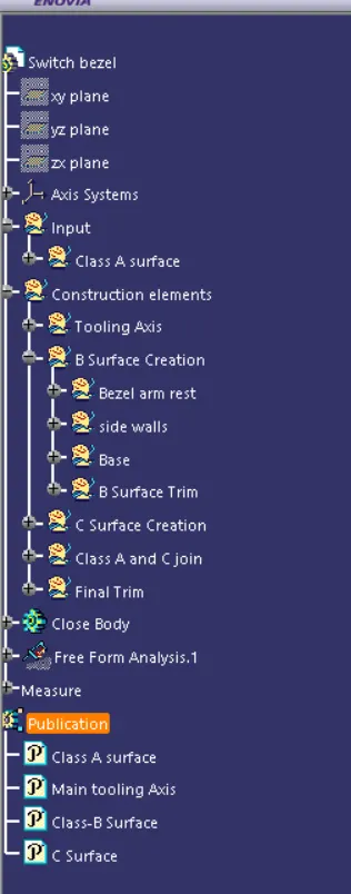
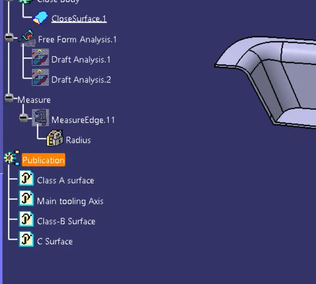
Publications: Use the publication option and publish the below-
- Tooling Axis
- Class A, B, and C surface
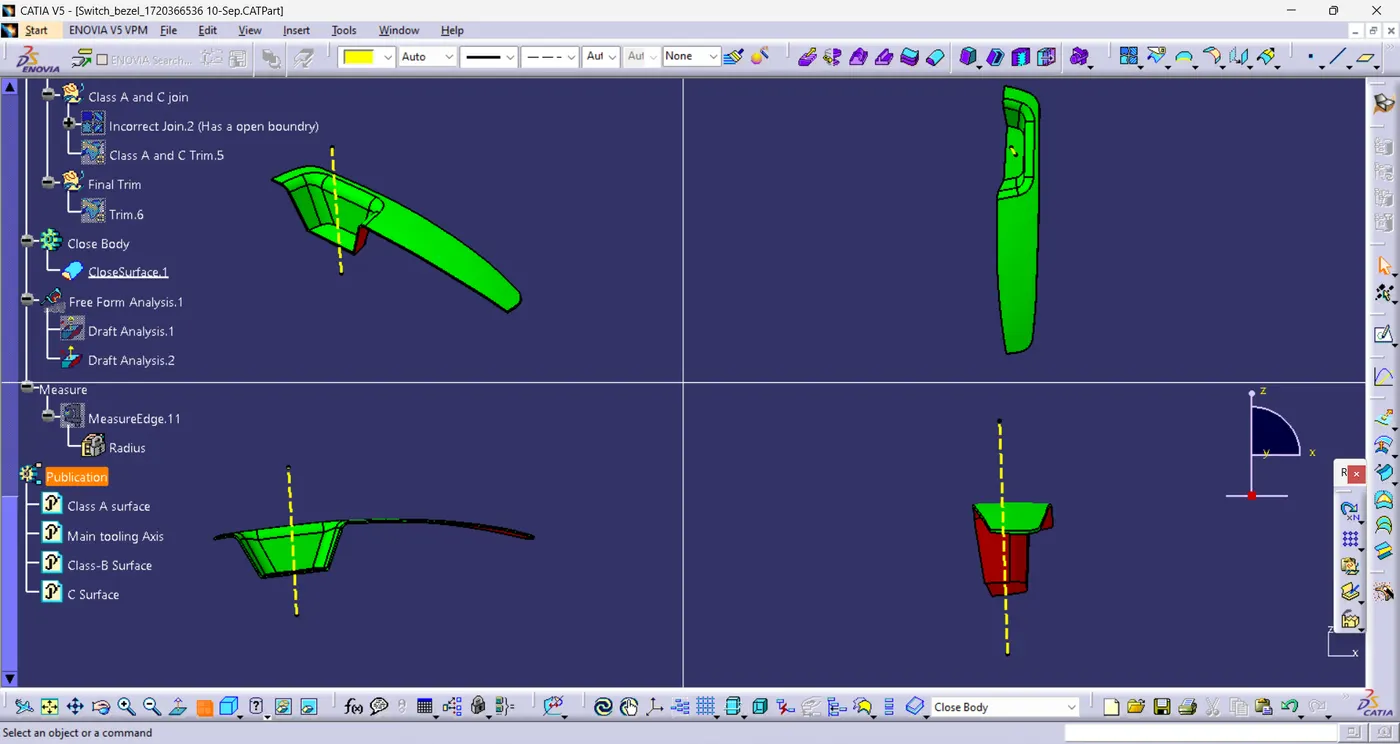
Screenshots of the solid model with the proper color code of the draft angle in various orientations (Isometric, Front, Side, and Top View)-
RESULT:
By the end i have Created the Switch Bezel Plastic component through the given class-A surface by following the operations that are listed below :
- Checking continuity of class A surface.
- Deciding feasible tooling direction & creating tooling axis.
- Performing draft analysis on class A surface.
- Creating class B surface from given class A surface.
- Creating class C surface to join A & B class surface.
- Creating solid feature by using closed surface.
- Performing draft analysis on final plastic component.