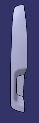
Week 9 - Challenge 2 - Switch Bezel Design
Given Class A Surface:
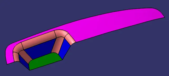
Tooling Axis:
A point is placed on the center of the bottom surface of the class A surface.
The Class A surface is intersected along the yz plane.
The two slant lines are bisected to get a new line along the point on the bottom surface.
The Class A surface is intersected again along the xz plane.
The slant line obtained from the intersect and a new line drawn at a 3 degree from the point on the bottom surface are bisected to get a new line.
The two previously obtained lines from bisecting is bisected with each other to obtain the tooling axis.
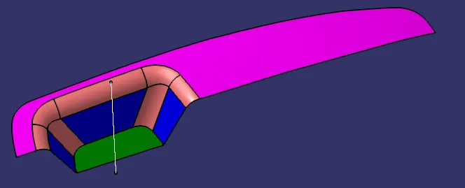
CLASS B SURFACE Creation:
BEZEL REST SURFACE:
The switch bezels hand rest part of the surface is extracted and untrimmed.
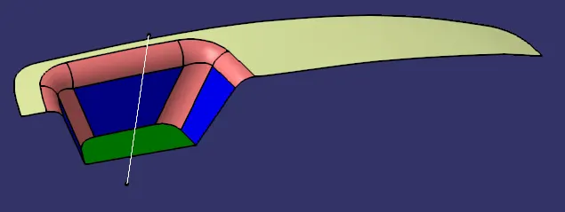
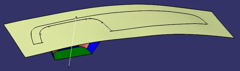
WALLS:
The wall surfaces are also extracted and untrimmed.
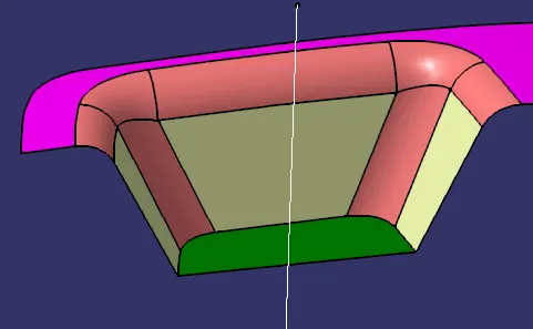
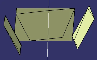
They are also extrapolated in order for them to intersect each other.
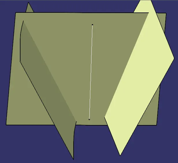
The wall surfaces are then trimmed with each other.
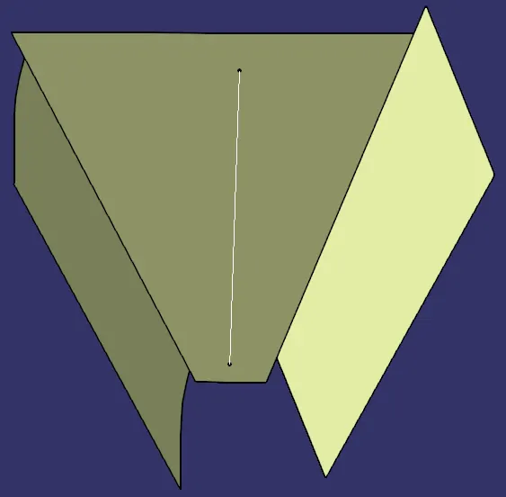
BASE:
The base surface of the switch bezel is extracted, untrimmed and extrapolated.
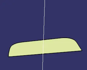
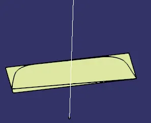
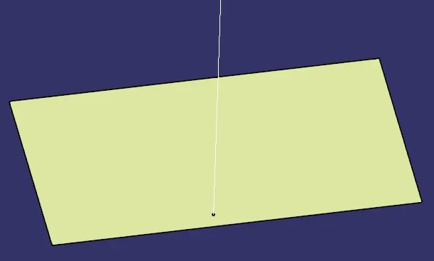
All the newly created surfaces are offseted by 3 mm to form the class B surface.
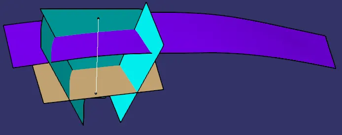
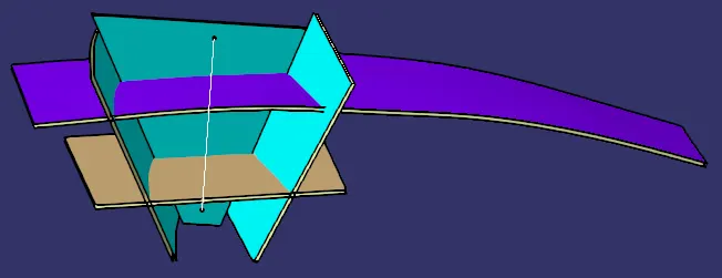
The offsetted surfaces are trimmed with each other to form the Class B surface.
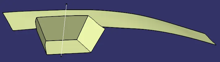
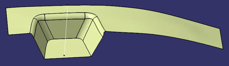
Fillets are added to the Class B surface.
CLASS C SURFACE CREATION:
The borders of the class A surface is extracted using multiple extract. The extraction process is done half of the borders at a time.
The extracted curves are smoothened to produce smooth curves.
The curves are then swept with an outwards draft angle of 3 degrees.
The edges are extrapolated and trimmed to form the Class C surface.
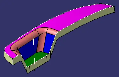
Closed Surface:
Join Class A and Class C surfaces.
Trim the joined surfaces with the Class B surface.
Use closed surface command to create the part body using.
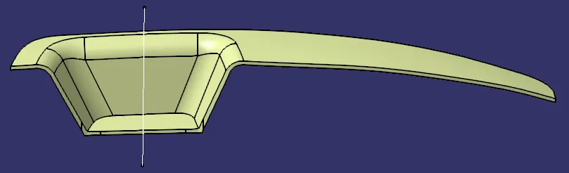
Draft Analysis is performed to see if the part can be drafted or not.
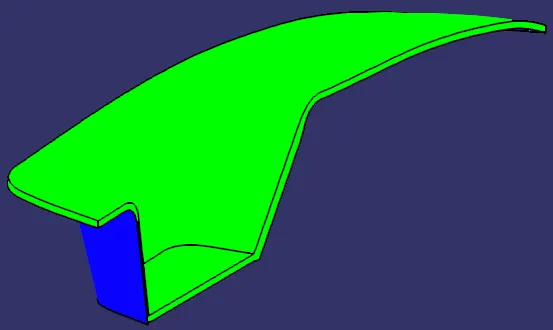
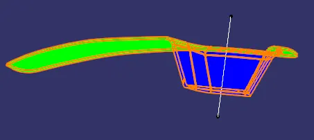
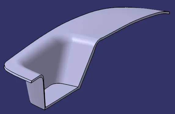
Isometric View:
Front View:
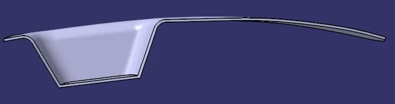
Side View:
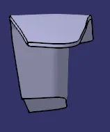
Top View: