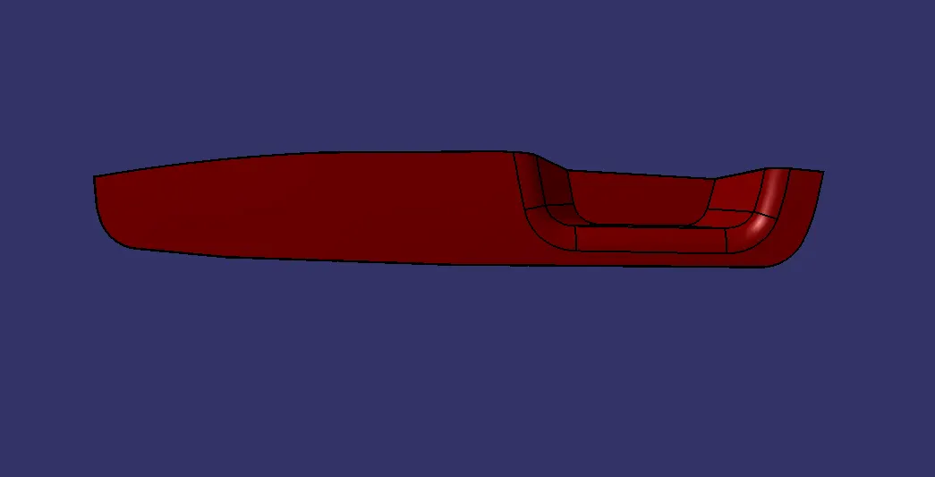
Week 9 - Challenge 2 - Switch Bezel Design
Objectives:
- Creation of Tooling Axis.
- Creation of Class B and Class C surface with referance of Class A surface.
- Creating a solid part out of surface modeling.
- Draft Analysis of Class A surface and final plastic component.
Tool Used to create model: CATIA V5
Introduction: We are designing a base bracket using given class A surface. The approach includes creation of Class B surface keeping 2.5 mm of thickness in mind for the complete component. The design also included Class C creation from the given parent surface.
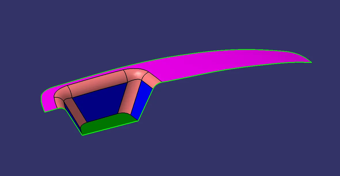
CLASS A:
Following surface is given as the input for the component creation. To design the part model we have to find out the tooling axis for the surface and check the drafts Analysis.
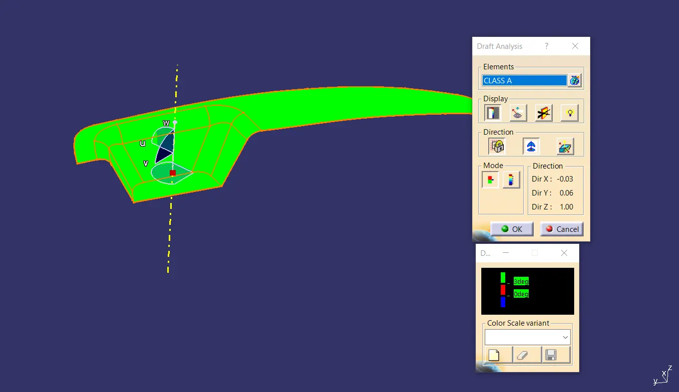
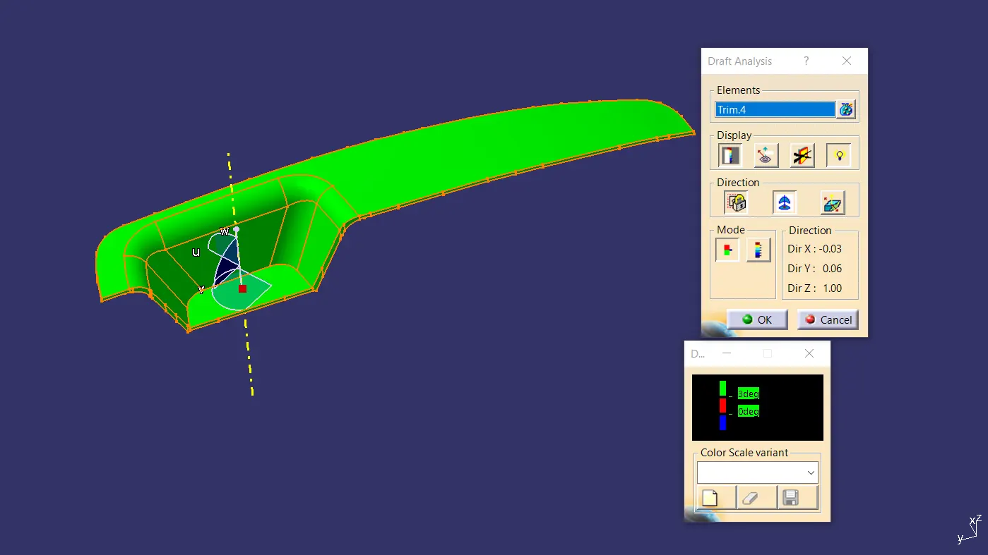
Draft Analysis of Class A Surface :
The analysis is done with 3 degree draft angle. As we can seen all the surfaces are more than 3degree. All the surface is in green colour is draft by 3 degree or more than 3 degree.
Tooling Axis:
- First we create an intersection of CLASS A surface with and from the intersection created the tooling axis as shown below.
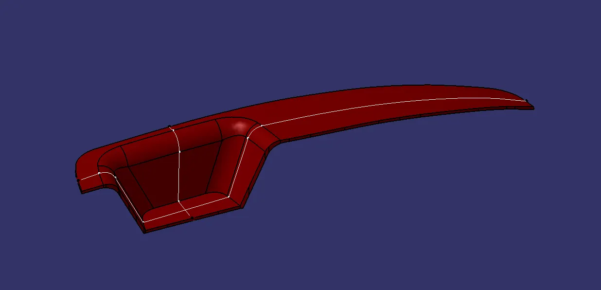
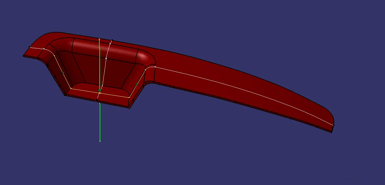
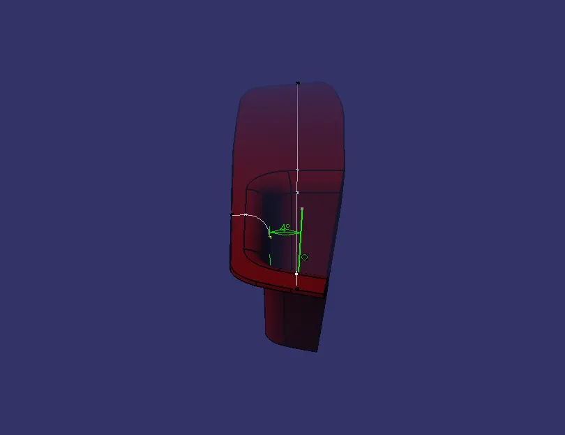
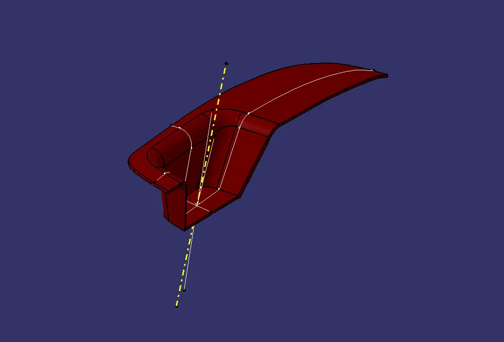
- Created a bisecting line using the lines shown.
- Here, Line shown in dotted yellow line is our tooling axis.
Creation of Class B:
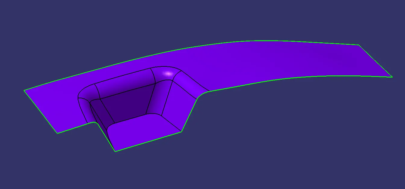
- Now for Class B creation, we have extracted surface from Class A and untrimmed them to obtain the original parent surface.
- Then offseted to the required thickness(That is 2.5mm).
- After offsetting, all the surfaces we trimmed into the required shape.
- After that required fillets are given to the surfaces.
Creation of Class C:
- For creating Class C surface we have extracted the boundry of Class A using multi-extract and then converted to smooth curve.
- Now this smooth curve is sweep along the draft direction with a 4deg draft.
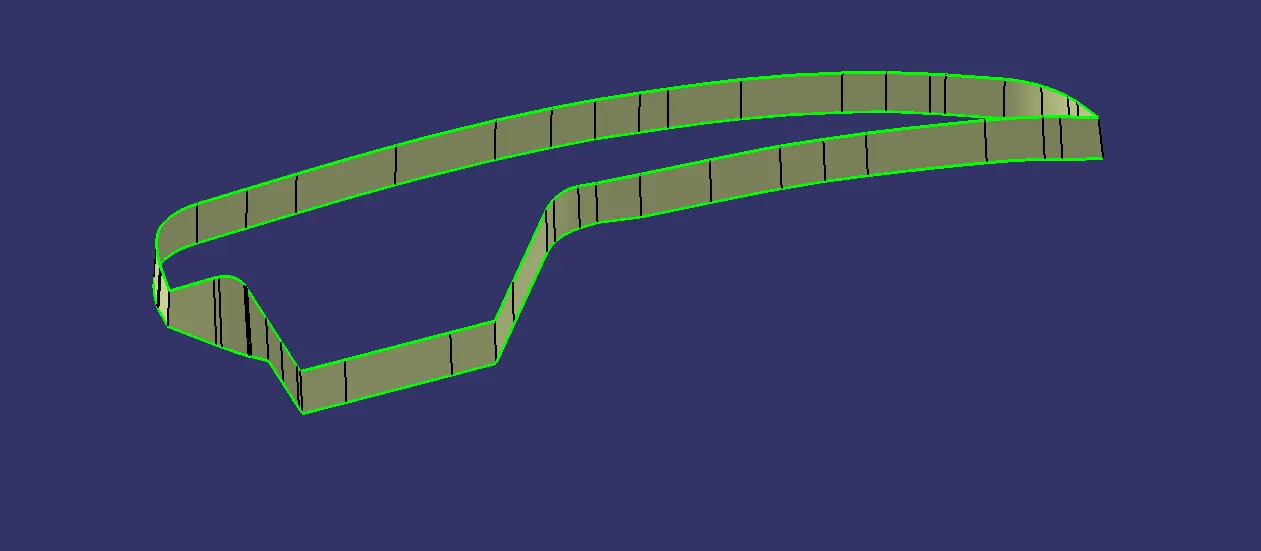
Trim or Join
Class A + Class C:
We make sure that there is not any open boundry between class A and class C, we have to join them to created the single body.
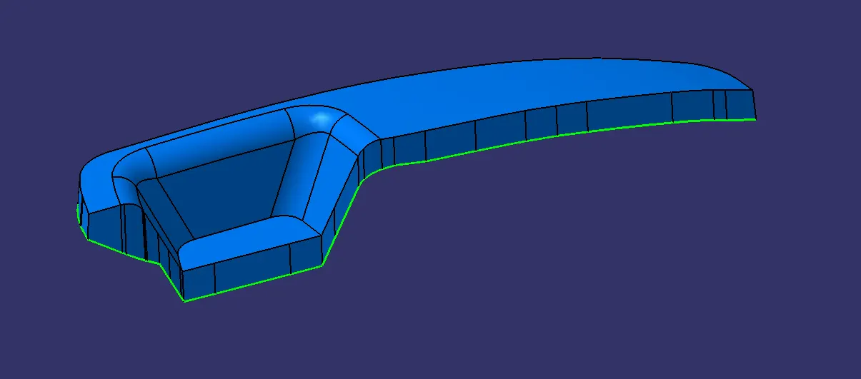
Final Trim or Part
Class A + Class B + Class C:
For this we have trimmed the above shown surface with the Class B surface using trim feature.
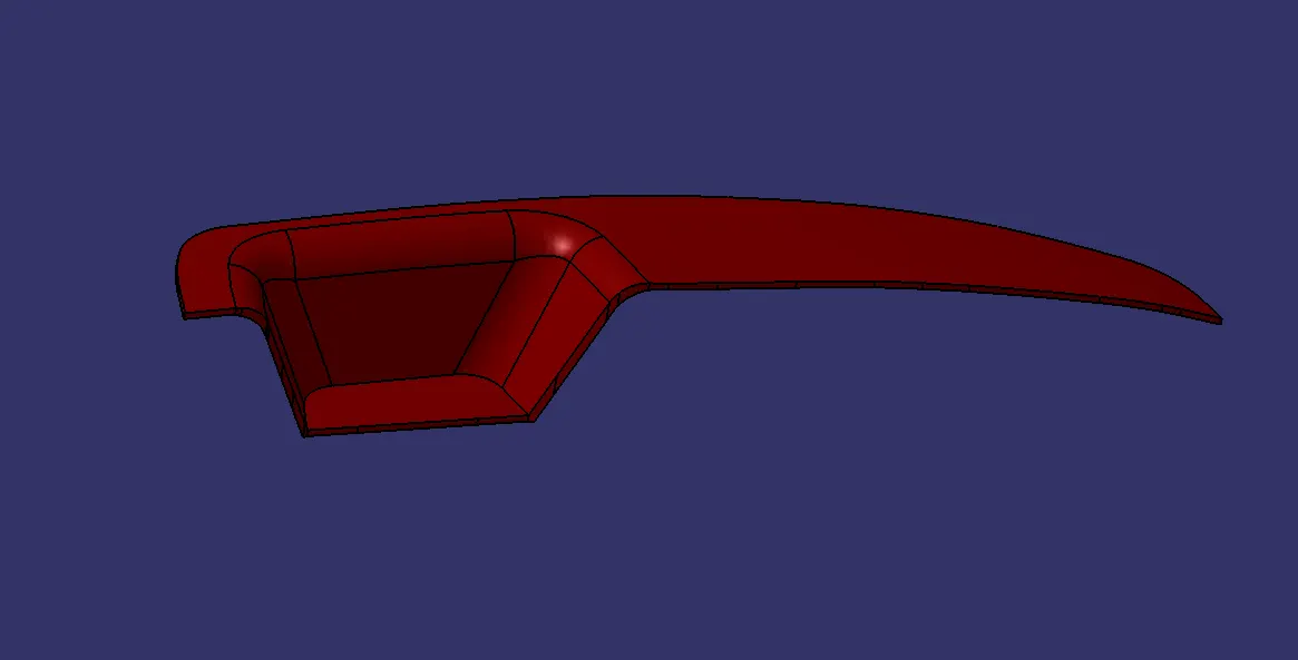
Draft Analysis of the Final Component:
For this analysis, tooling axis is taken draft reference.
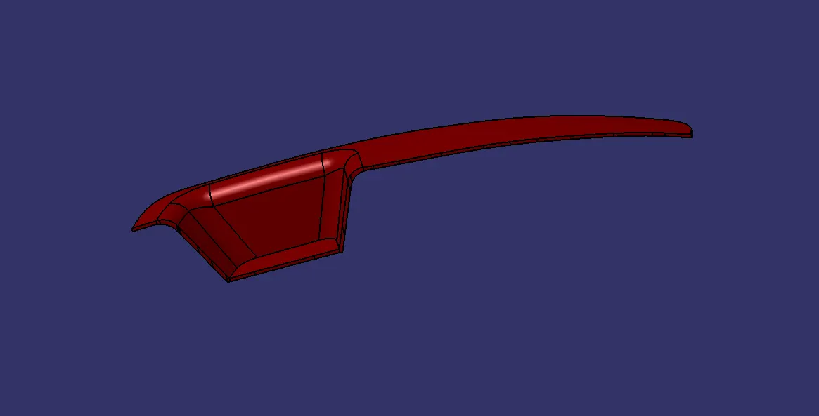
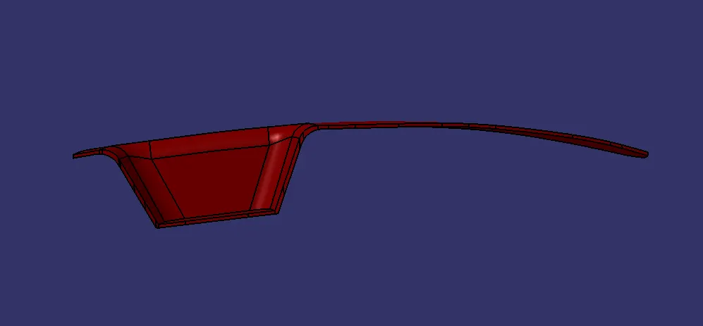
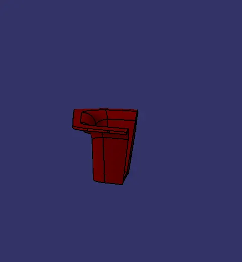
Different Views of the final plastic component.
Isometric View
Front View
Side View
Top View