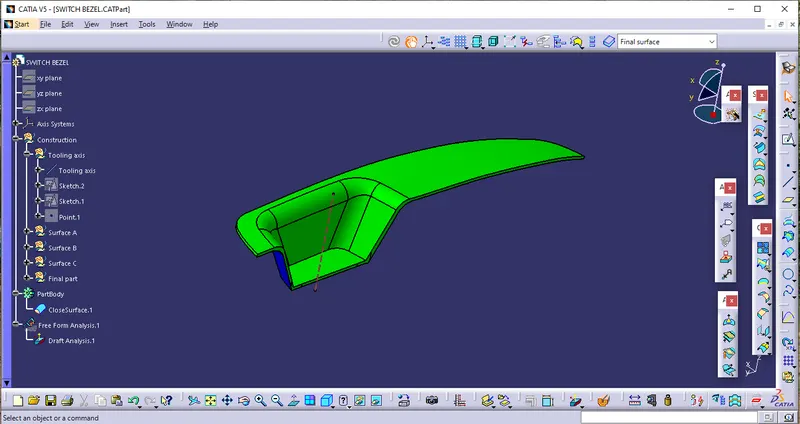
Week 9 - Challenge 2 - Switch Bezel Design
To create the plastic component of the Switch bezel with the Surface given we follow the given steps
Step 1
after getting the surface A we can create the other surfaces with the tooling axis reference to get the tooling axis we have to create two seperate dummy axis because the surface has the two different areas to get the axis instead of a full closed surface after get the two axis we can create the exact tooling axis with help of bisecting line of the both axis
Step 2
After that we can create the geometrical set for the each surfaces seperately before that we can get the draft analysis for the surface A which is given we can use the draft analysis command from the insert opition and by selecting the feature analysis to analysis the surface A
after that we get the toolbar which used to analyse by using compass we know the angle of the surface which is below 3 deg or above or equal to 3 degree for better understanding
Surface B
then we insert the geometrical set for tooling axis which used as a basic axis for the remaing surface creations then we create the surface B by selecting the part with using of the extract and untrim commands to create the b surface by creating the offsetof 2.5mm to create the final part
surface C
then we create the surface C inside of a seperate geometricl set and with reference of surface a and using the boundary and sweep command we can get the surface c and we can finnaly trim the surface c with surface b to get the final plastic part and we can check the draft analyse of the final part same as surface a analysis to check the degree the axis of the part and then we can create the part as a closed surface at part workbench as final part
Draft analysis
after geting a closed surface body we can use the draft analysis to get the detais about the degrees of the ploted part to know it is under the 0-3 degree variation
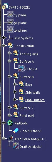
Tree structure
Surface A
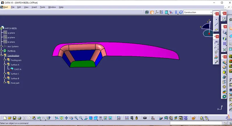
Surface B
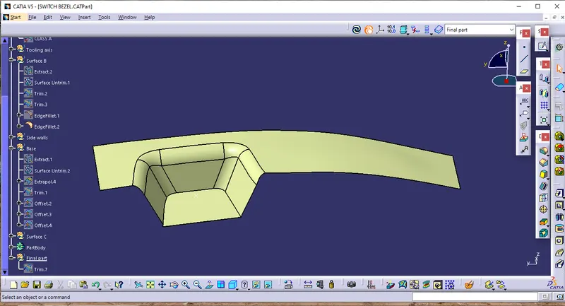
Surface C
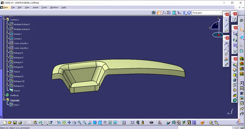
Final surface
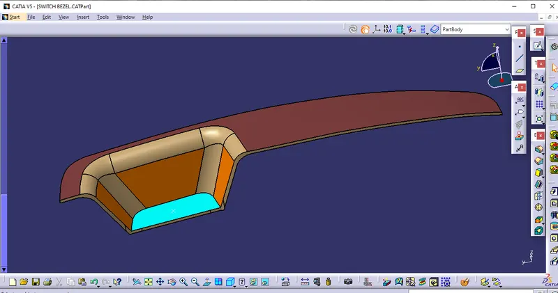
Closed surface
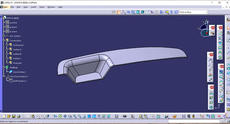
Draft analysis