Week 9 - Challenge 2 - Switch Bezel Design
Switch Bezel Design
Aim:
To create a Closed surface component of switch bezel through the given IGES/STEP file in Catia V5 by constructing Class B and Class C surfaces by extracting Class A.
Construction:
1). Open IGES/STEP File.
2). Check whether any open in class A surface, if any "Join" all surfaces and make into single surface.
3). We need tooling axis to create the Class B and Class C surface to be feasible for manufacturing.
4). Insert a new geometrical set and name it as “construction”, insert another geometrical set and name it as “Tooling axis” as child for construction.
Tooling Axis
i). Extract the surface needed, Create point on the surface, and create a axis system on the points, Create a position sketch at that point, Intersect the surface through the plane, draw two lines at the angular profile.
ii). Create Bisecting line for the edges lines created.
iii). Create as another Bisecting line in another direction, But there is no another edge to create a Bisecting line create a constraint of minimum draft angle of 3deg, bisect both lines.
iv). The bisecting line is taken as final Tooling axis.
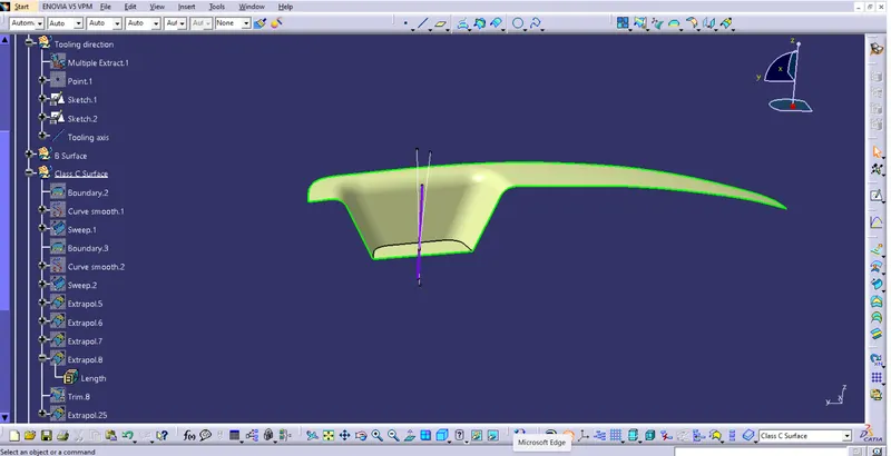
4). Insert a new geometrical set and name it as “B surface” and another child geometrical set “Bezel rest surface”. Extract the surfaces of the bezel region. untrim the surfaces and offset the bezel rest surface to 3mm.
5). Insert a child geometrical set “Walls” and extract the wall region of bezel and untrim it Extrapole and trim it with bezel rest and offset to 3mm.
6). Insert a child geometrical set “Base”. Extract the base and untrim, offset to 3mm and radius the edges.
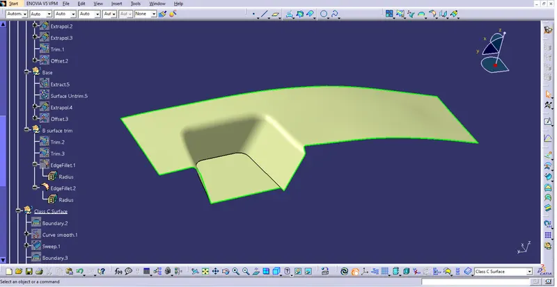
7). Insert a child geometry “Class C” for construction. Take the Boundary of class A surface in 2 patches by using first point and second point. Smooth curve to do Sweep along the tooling direction, Extrapolate the edges and trim it. Later, Join with class A surface (sometimes Class A need to be extrapolate and trim with class C .
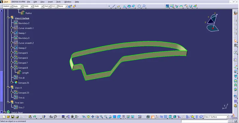
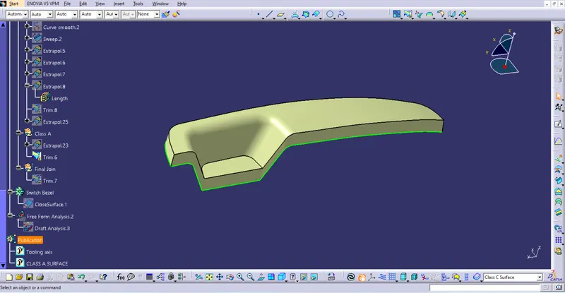
8). Insert a new child geometrical set "Final trim". Unhide the Class B and trim it with joined Class A.
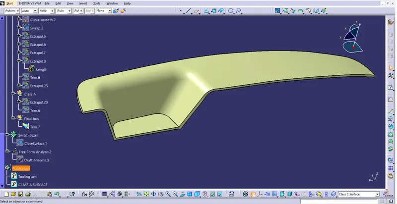
9). To create a closed component.
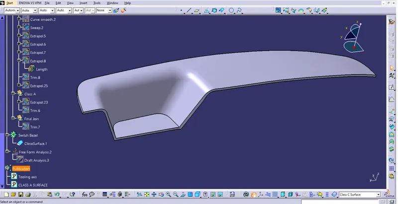
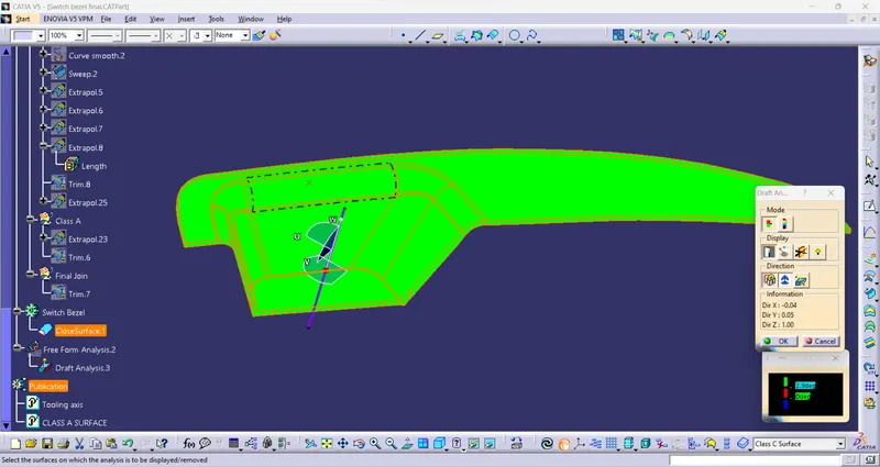
10). Final step is to check the component is feasible for manufacturing using Draft analysis.
Draft Analysis
i). Insert --> Analysis --> Feature draft analysis --> Set the compass on the tooling axis --> Lock the position --> Click on the component.
ii). My design is passing 2.9 Deg.