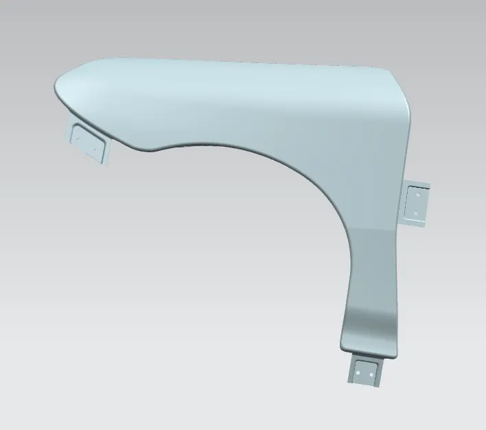
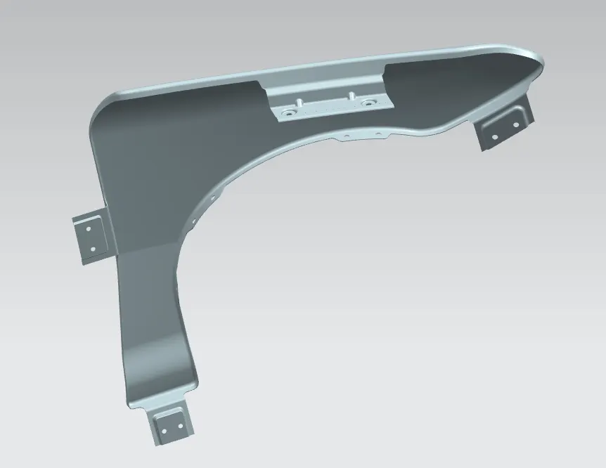
Fender Design
AIM:
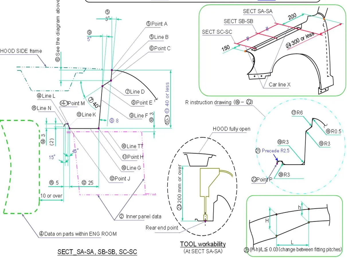
To create a fender model and provide mounting areas for bumper, engine, A-Pillar and engine compartment area along with drip area by refering standards
PROCEDURE:
1. Import the Class A surface and save as part file.
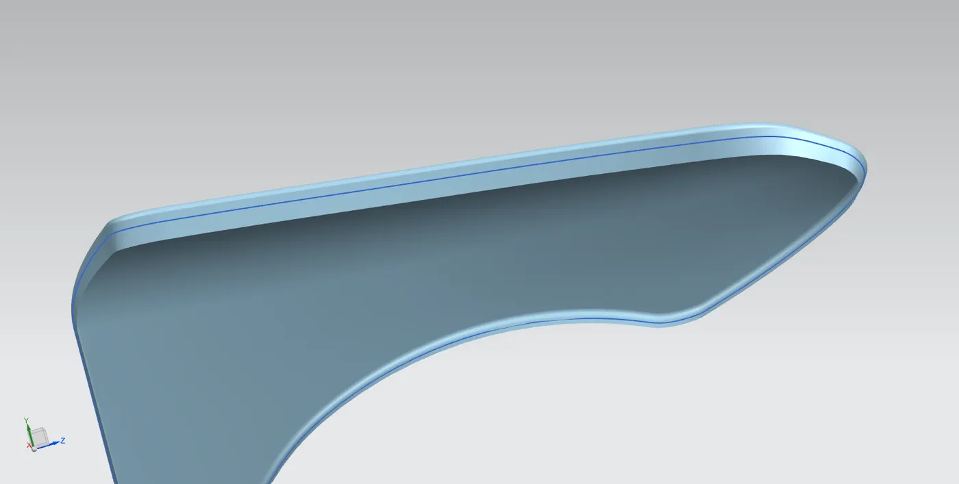
2. Offset curve 5mm towards inner, as shown in pic
2. To create engine mounting, create planes at 200mm from the A pillar mounting edge and another plane at 150mm from bumper mounting edge as per standard, create a bridge curve at the intersecting point and using law extension at the required angle as per std drip area is created along with embosses and darts for strength
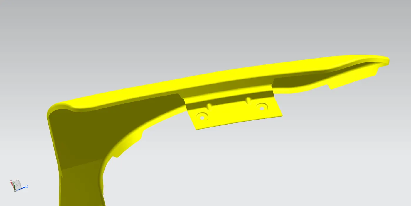
3. Using same method Bumper mounting and other mountings also created
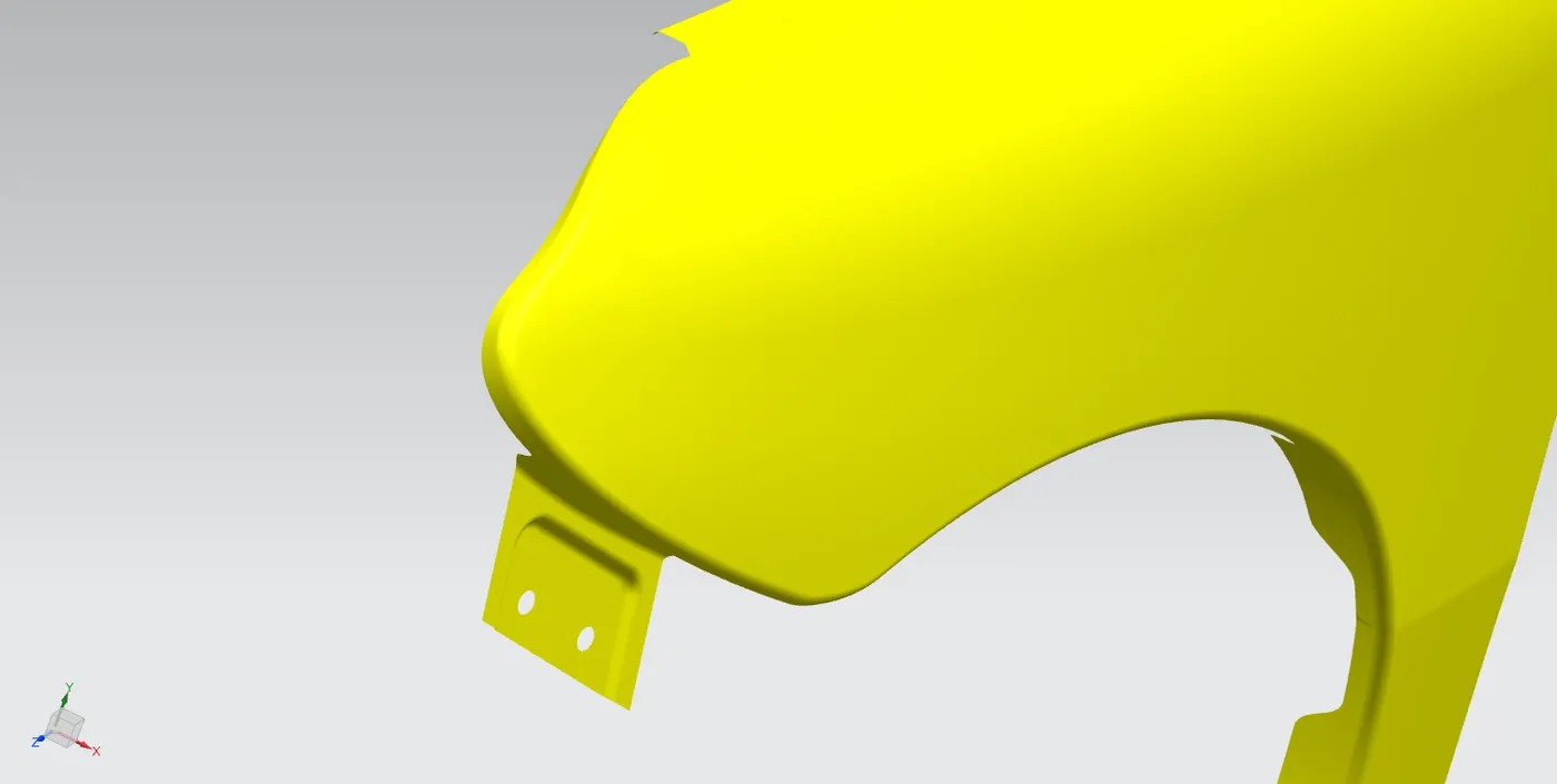
(Bumper mouting)
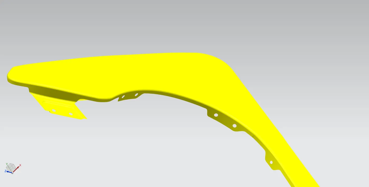
(Wheel arch mouting)
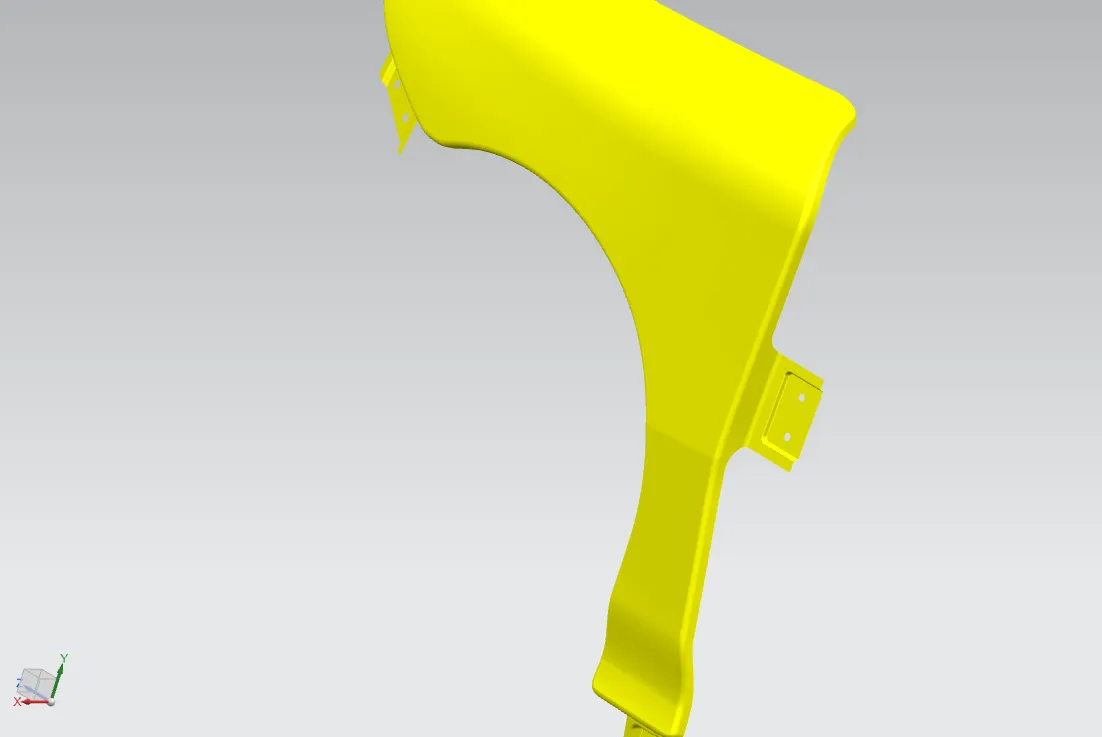
(A pillar mouting)
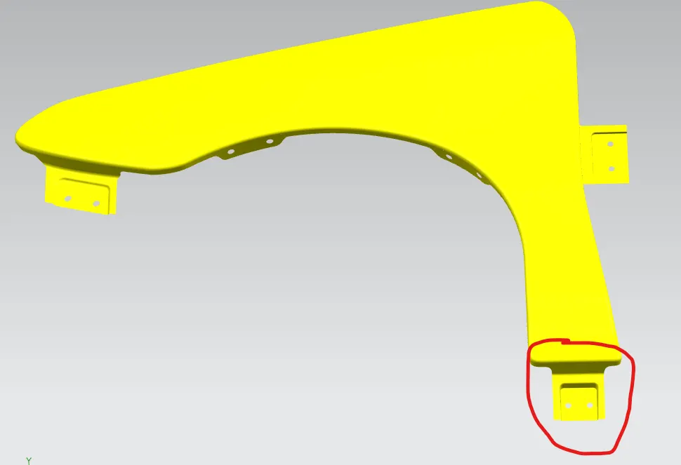
(A sill mouting)
4. Finally part is thickened to 0.7mm thickness