Hood design-Week 2
HOOD ASSY
Output File:
https://drive.google.com/drive/folders/1s5T2e1MJL_hCCdGlWvcVtz9CpvOX_ZHO?usp=drive_link
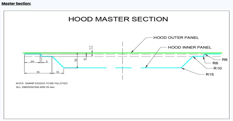
MASTER SECTION:
Design approach using NX-CAD
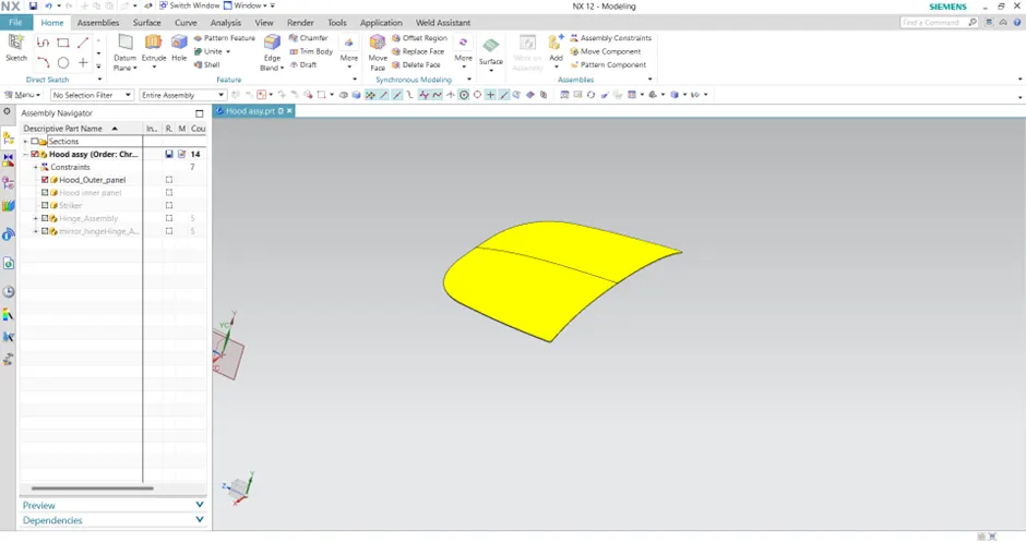
1. Inserting outer panel into NX-CAD
Create New Assembly → Give name = Hood Assy → Assemblies → Add component →Open folder(Select Hood outer panel, skin data download from webpage)→ Assembly Location → WCS → OK
2. Create New component (Hood Inner Panel)
Assemblies→Create New Component→Choose Model→Give name= Hood Inner Panel→Select same location→OK
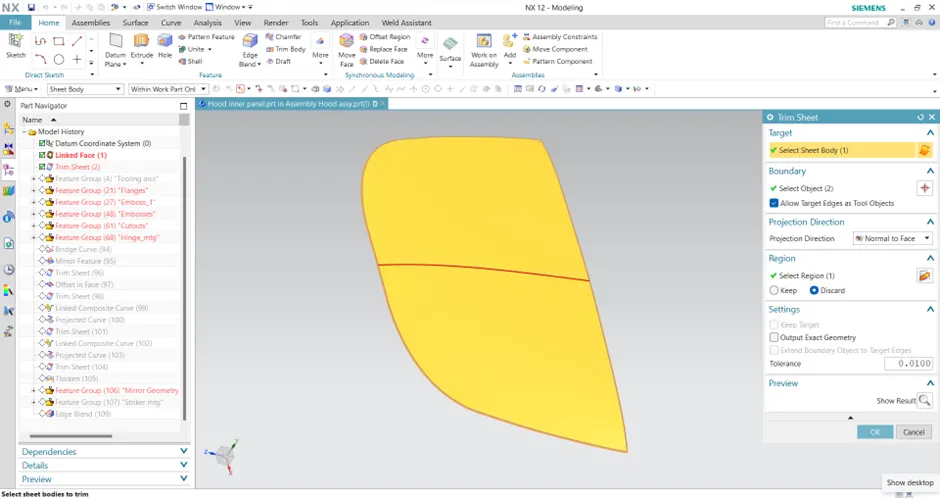
Hood Inner Panel created → Make Workpart → Assemblies →WAVE geometry linker → Select Hood outer panel skin data → OK
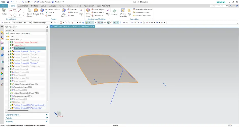
Surfaces → Trim sheet → Select sheet → Select Boundary as ZX plane → OK
3.Create Tooling Axis
Create a New Sketch in YZ plane→Draw a line at the edge of the trimmed sheet
Create anothe line perpendicular to the line already drawn → Create New Feature Group → Rename as "Tooling Axis"
4.Create Inner Panel
Surface→Offset surface→Select trimmed sheet→Offset to 0.75mm in inner direction→OK
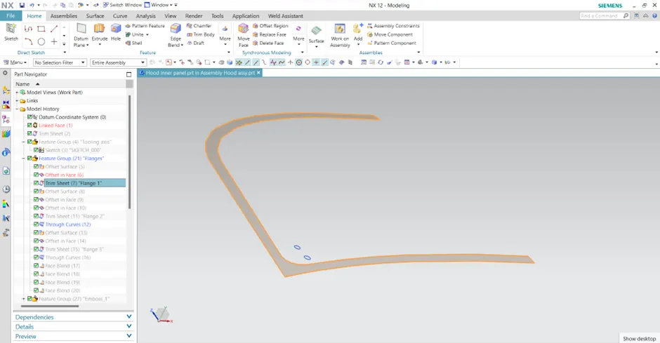
Curve→Offset curve in face→Select Edges and Face→Offset to 20mm as per master section→Fillet = Best Fit, radius=30mm→Select trim to face edges, Edges to face edges→OK
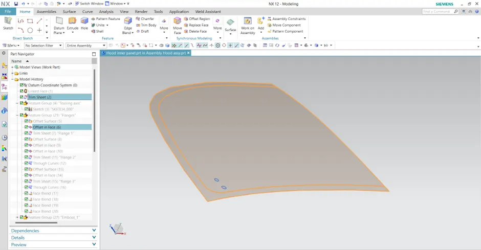
Surface→Trim sheet→Select sheet and boundary→OK
Rename to Flange1
Next, again one more offset needed as per master section
Surface→Select working surface→Offset to 4mm →OK
Curve→Offset curve face→Select the edges and create two offsets→offset to 22mm & 35mm
Trim unwanted region and rename as "Flange 2"
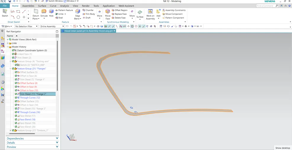
Create a new surface between 2 flanges
Surface→Through curves→Select two edges→OK
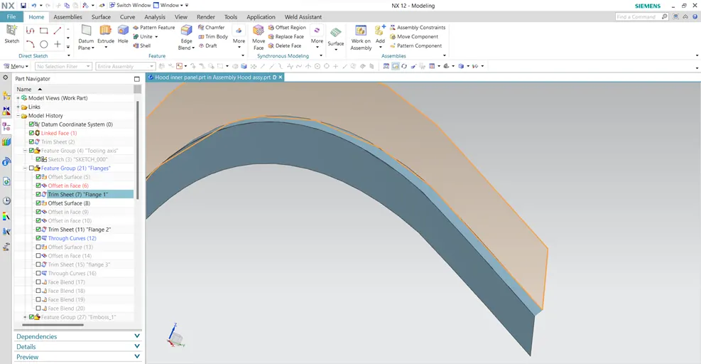
Create another offset of working surface to 25mm→ Offset curves to 50mm →Trim sheet→Create a surface between them using same steps followed previously→Rename as "Flange 2"
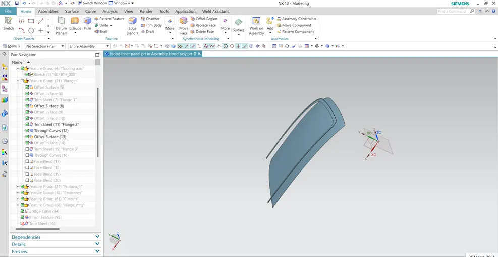
Apply Blends
Surface→Face Blends→Give Radius as per master section→OK
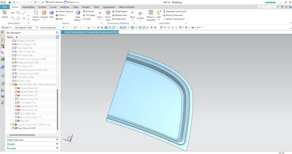
Create Embosses
For creating embosses, first import striker and hinges,
Assemblies→Add→Select striker from folder→OK
With same way add hinges also
After measuring horizontal and vertical distance of tge striker create a sketch in XZ with 5mm to 10mm clearance to create edge blend to avoid stress concentration
Using Project curve tool, project the curves drwan on the plane to the surface after constrain all the curves
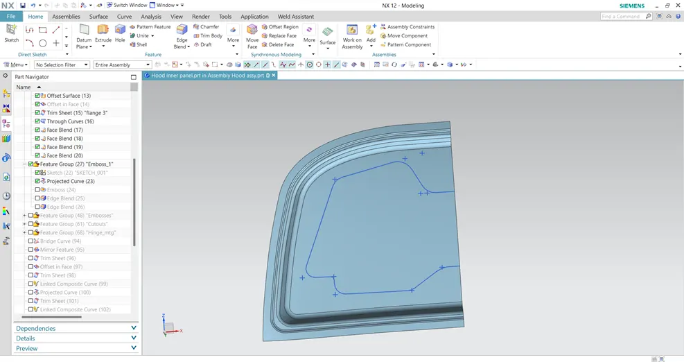
Next, Emboss is applied
Surface→More→Emboss→Select the curves and face, considering min draft angle 7deg i have taken 10deg, end cap depth is 10mm, choose vector as already created tooling axis
Give Egde Blend of radius 6mm, create a new feature group and name as "Emboss 1"
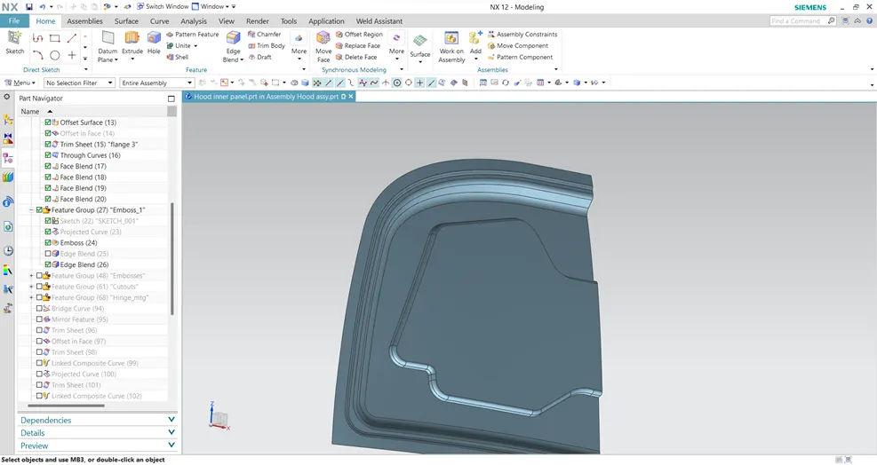
Create 2nd set of Embosses by creating sketch in same plane using same tools followed before
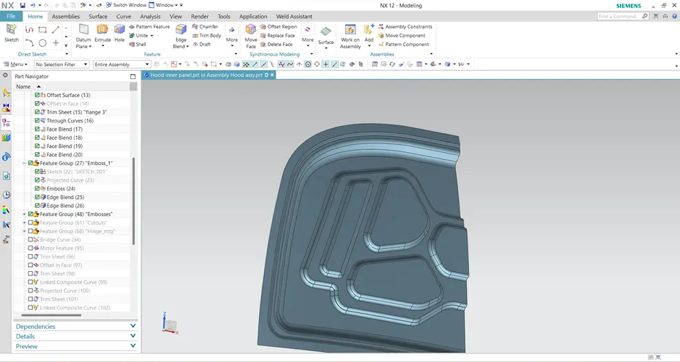
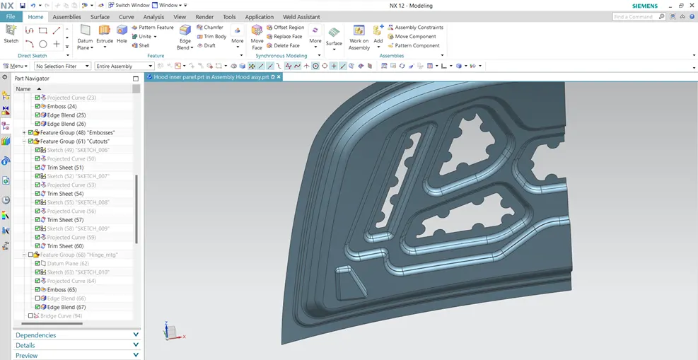
Creating Cutouts
Next step is to create cutouts by creating sketch in same plane and draw the curves along mastic points
Project curves to the face→Surfac→Trim sheet→Select boundary and face→OK

Creating Emboss for striker and Hinge
For Hinge mounting, Create a plane in Hinge rotating axis, at ZX plane and through axis is X axis, give the angle as -7deg and offset the plane at 590mm
Initially create Hinge mounting area draw sketch on the plane apply Emboss select the direction of emboss as tooling direction, End cap will the datum plane and give angle then OK
Give edge blends to avoid sharp corners
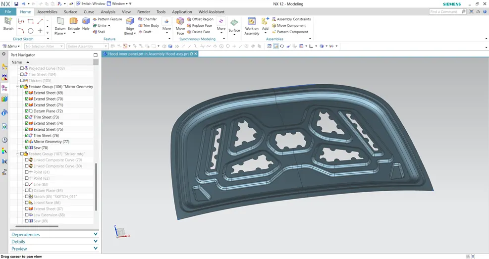
By applying Mirror Geometry
Extend tthe sheet little bit to avoid gaps inbetween
Menu→Insert→Associative copy→Mirror geometry→Select surface and plane→OK
Trim both the sheets and Sew it together
Next start moving hinge assembly to hinge mounting area, for that hinge has to be fixed with the sewed surface by applying constraints
Assemblies→Assembly constraints→Apply necessary constraints→OK
Mirror assembly to the other side
For striker mounting a sketch need to be created about the hinge rotating axis through which striker lock will happen with mating part
Initially a line is drawn at centre of two hinge assemblies to create a trajectory line and a circle of approx radius is created to the center to that line, again a line on top of the circle a line is created to fix striker using assembly constraints and rotated about the axis close to the sewed surface and applied blends to created emboss for striker mounting
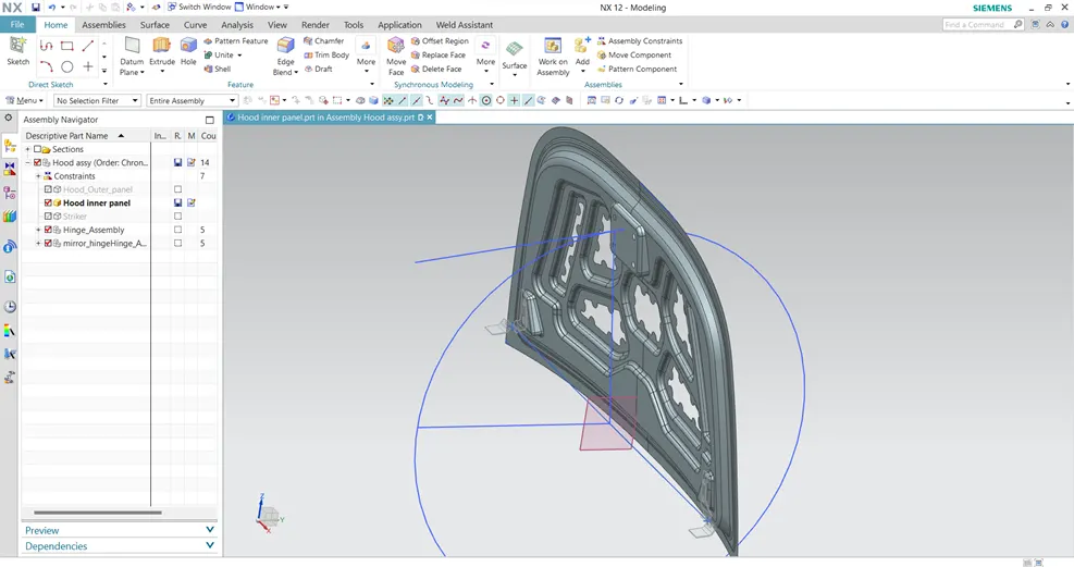
Creating Hemming
Referring Master section minimum gap between sheets must be 0.2mm and 2mm for the edge of the other sheet
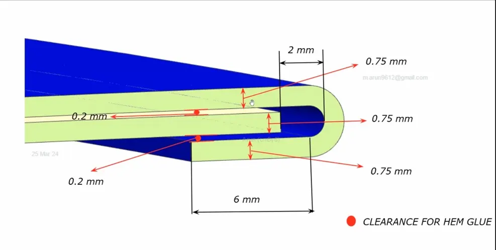
Select the bottom surface offset curve in face to required level trim the sheet to get lower hemming region. Using Law extension join top and bottom surfaces and applying three face blend
Hemming requires less material near the edge meeting points to avoid shrinkages. So, considering all these design reules hemming is created
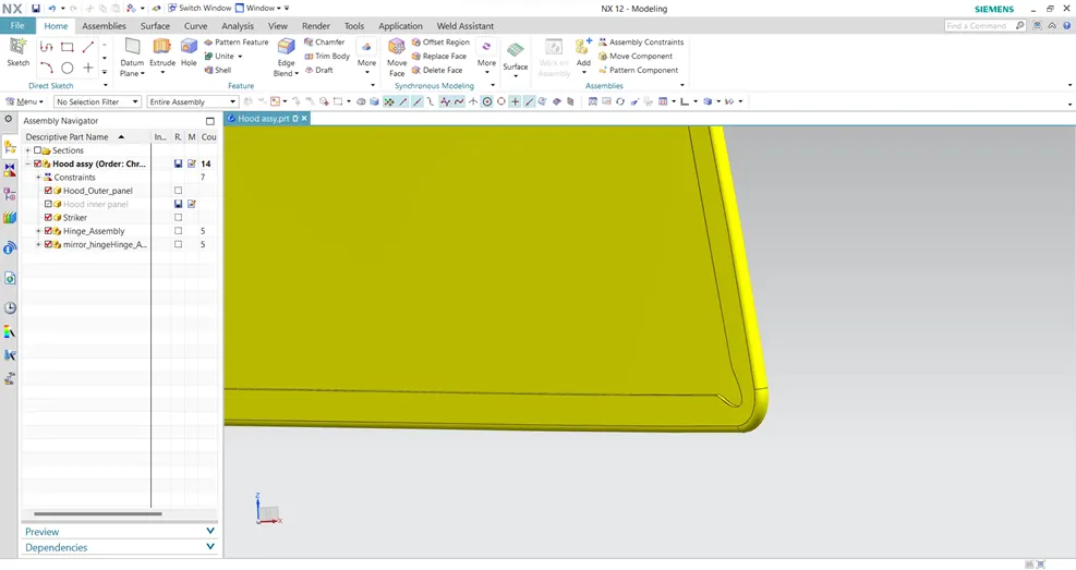
Finally surfaces has to be thicknened to 0.75mm thickness of the sheet
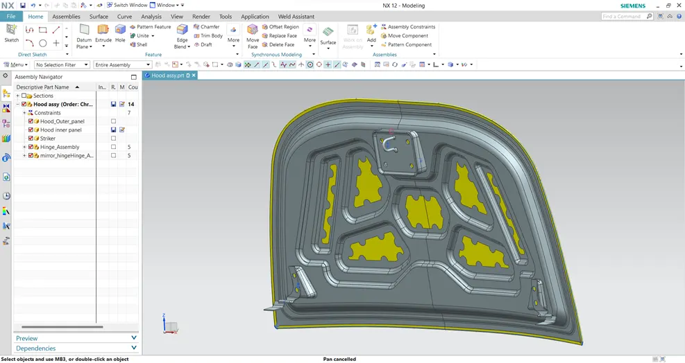
Final Hood Output
Output file : https://drive.google.com/drive/folders/1s5T2e1MJL_hCCdGlWvcVtz9CpvOX_ZHO?usp=sharing