Challenge 4 : Concept Modelling of Alloy Wheel
CONCEPT MODELLING OF ALLOY WHEEL
For this project, I have used Renault duster alloy wheel, which is more stylish.
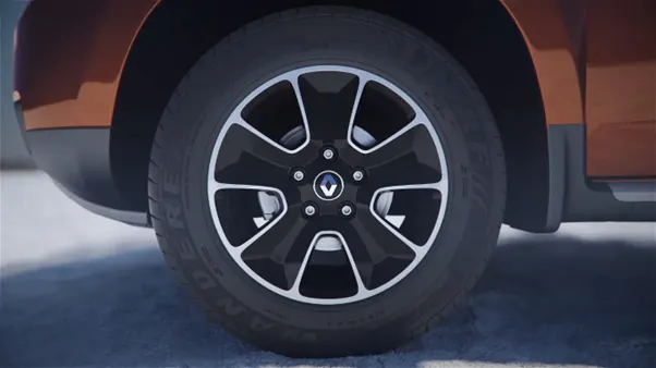
OBJECTIVE:
Objective is to create an 3D design of the alloy wheel approximate scale that matches the real design using Autodesk Alias 2023.
ABOUT THE PROJECT:
Alloy wheels are class A parts, more stylish models are more attractive. Through, this project I have learned to visualize an alloy wheel and design the same by concept modelling approach.
DESIGN METHODOLOGY:
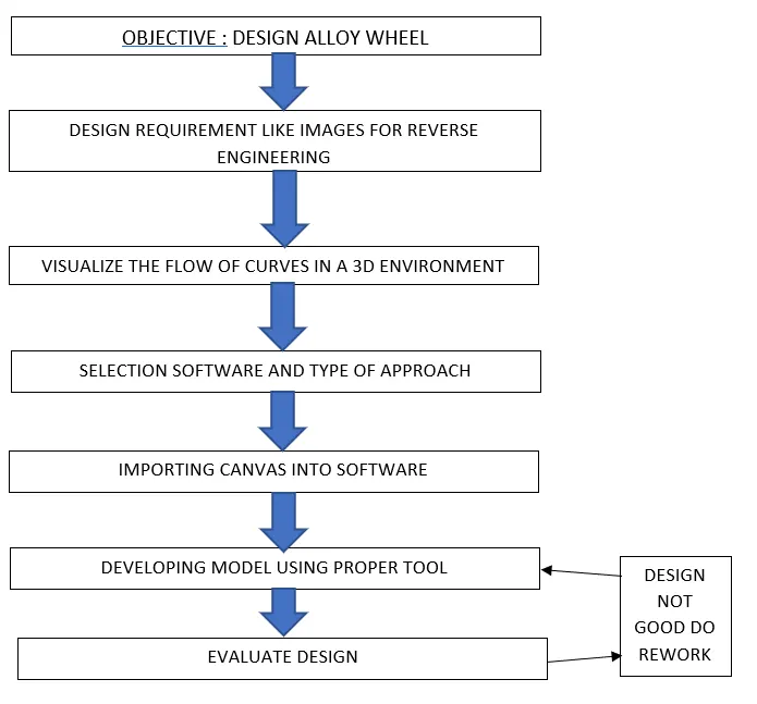
DESIGN HISTORY:
To start designing first canvas image is imported in respective plane. After importing canvas image, image is scaled down to the required size. Using plane editor feature the contrast of the image is adjusted to make it more transparent.
Then the first outline is done using circle feature and scaled to fit the outline of the alloy wheel as in the image. A parallel line is drawn to the Y axis in the canvas image and another line of 54° from X axis is drawn to divide a segment of alloy wheel. Later, using detach command the circle drawn is detached at the points were a segment of alloy wheel starts and ends. Another circle is put and moved in Z-axis since, the center surface is little inside. Detached curves and another circle drawn at center is connected to form a surface later. The connected G2 CV’s are given with 3 degree and aligned parallel to Y-axis.
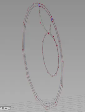
Image (1)
Hence a smooth curvey surface is formed using rail command as shown in the below figure.
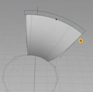
Image (2)
Using layers feature Canvas image, curves and surfaces are separately assigned in their respective layers. The mid part in the alloy wheel is build by the same CV feature and adding G2 blend curves the edges are joined to the skin and CV as shown in image (3).
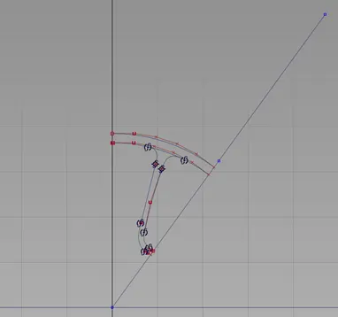
Image (3)
Then the curves are projected to the pre-form rail surface and trimmed out. Planar command is applied on the center circle parts given 3 degrees to it their CV points are adjusted to from a dome shape surface as shown in image (4).
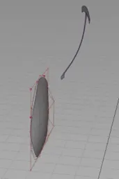
Image (4)
The 54° and parallel line is projected to the surface and trimmed to maintain the segment size and scaled it little bigger. Same as the flat end the surface that flow at the inner part of the alloy wheel is build by CV curves and blend curves as shown in image (5).
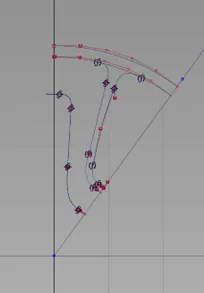
Image (5)
Using blend and skin feature all surfaces are joined and controlled to one span. In some places G2 surface is not generated hence using extend command the surfaces are extended and surface intersection is done then unnecessary surfaces are trimmed out. The surfaces formed are as in image (6).
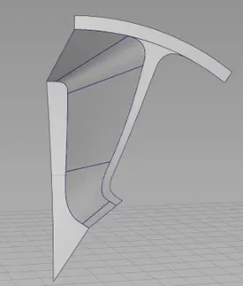
Image (6)
The right side surface is also build using as technique. Same as in left side surface some surfaces are not formed in G2(curvature) mode. So, they are extended to untrimmed top surface and intersected to trim it to form perfect segment. To do symmentry the plane is set to Y-axis and the symmentry is applied. The final step is to create the bolt hole swtich on the canvas image layer to become visible then the bolt hole is created using circle and skin options. One segment is fully created and all the surfaces grouped using ctrl+G option. The pivot of the model is moved to the center of the alloy wheel. Using duplicate object feature in edit option the number of segments is given 5 and the angle of rotation along Y-axis is given 60° then the final alloy wheel model is completely generated.
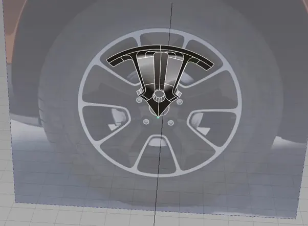
Image (7)
The final alloy wheel model is as shown belown;
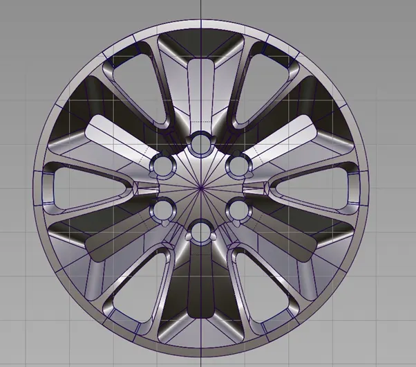
Front view
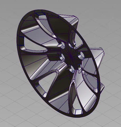
Perspective view