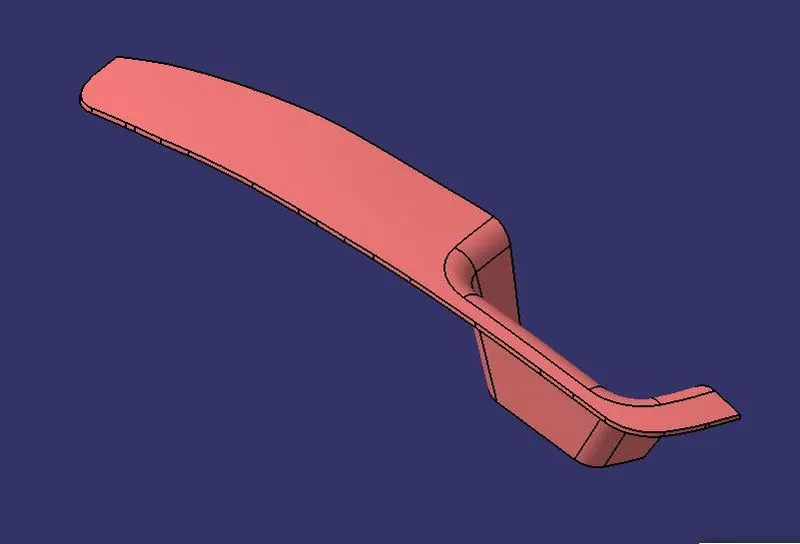
Week 9 - Challenge 2 - Switch Bezel Design
Objective:
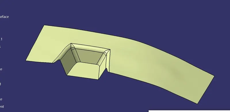
The main objective of this challenge is to create the Switch Bezel Plastic component through the given Class-A surface. To begin with, the tooling axis for the given Class-A Surface should be created meeting the requirements of the draft angle and at the end perform the Draft analysis on the model.
Switch Bezel:
Switch Bezels in car are parts which contains switches and controls for different functions like Window control, Door lock/Unlock,Media and Temperature controls.
Input-Class_A_Surface:
Here we'll download the class_A _surface by using the above link.
Tooling Axis:
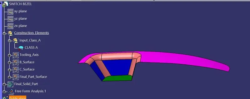
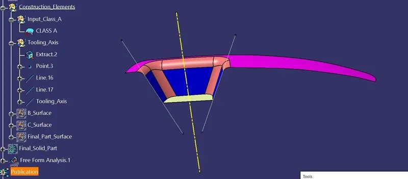
For creating the tooling axis I'm using the base surface in green colour by the extract option. I create the point on the middle surface. Then I decided to choose the side wall edges to create the lines on it with a colinear by using there vertexes. Later using that two lines and with the point I created the bisecting line for the tooling axis. It was shown below.
Draft Analysis for Class_A_Surface:
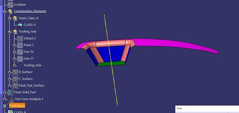
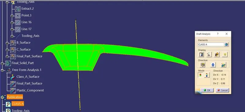
First we'll do the analysis for Class_A_surface. First we want to unhide class_A_Surface. Then go to Insert-> Analysis-> Feature Draft Analysis. Sometimes it'll some error for give material to this. We can make the part as material by using the material option. Then we'll do the draft analysis. For doing that we using the compass tool on the draft analysis window to place on the tooling axis and then lock it.
By clicking on the surface, the whole part turned into green color. If blue was visible that meant that the analysis was inversely done so just by flipping the direction, draft analysis.
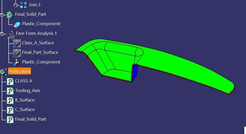
The green region shows the part which is toolable or produceable by the molding machine and the draft angle is 3degree.
Blue color region states that the part can be allowed in some OEMs but still need to be improved for the other OEMs as the draft angle is more than 3 degrees.
Red color which is not there in this case states that the draft angle is less than 3 degree and cannot be produced or if produced would be faulty.
Class_B_Surface:
Side Walls:
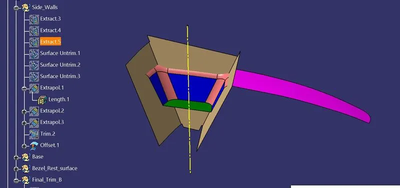
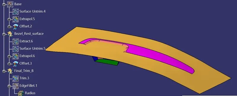
Then I decided to create the B surface offset to 2.5mm. First I used the walls on the A_Surface extract it, untrimmed then extrapolated that surfaces. Later I trimmed that surfaces to get the walls. Then offset to the 2.5mm.
Base:
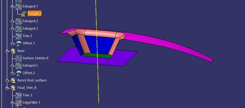
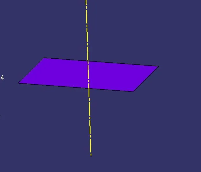
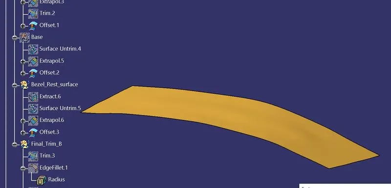
I'm using the same procedure for the base surface in the green colour. Then offset to the required distance.
Bezel_Rest_Surface:
Later the last surface of the bezel rest surface is offset by using the same above procedure, then we'll get this output.
Final_B_Surface:
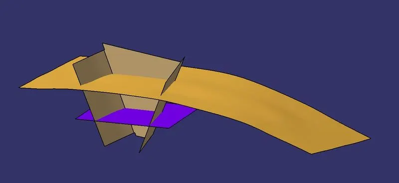
Then by using these 3 offset surface we'll trim them to get the final B surface, it shown below,
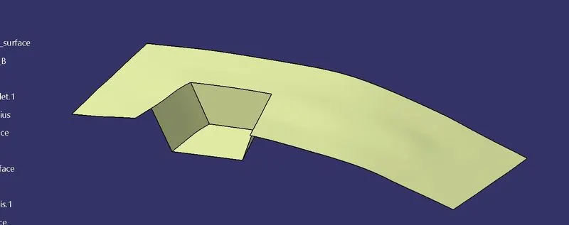
Then we'll give the smooth surface by using the edge fillet on the required edges. It is on the outer side so I decided to reduce the radius with the thickness value. Top 3 edges = 14-2.5=11.5mm. Side 2 edges= 15-2.5=12.5mm.
Class_C_Surface:
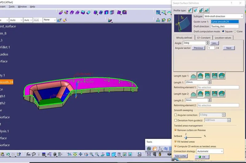
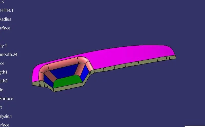
For creating the class_C_Surface, I'm using the boundary of the class_A_Surface. But the boundary has lot of edges on it that will create uneven surface finish. So I'm using the curve smooth option to smoothen the curve. Later using the sweep tool to create the C_Surface by using the tool axis for give the direction and the draft angle will be 3degree.
Final_Trim_Surface:
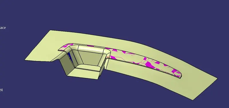
Then joining the A and C surface and later trimming the A,B and C surface to get the final output of the part surface.
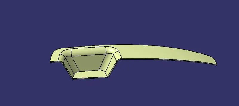
Final_Plastic_Component:
After creating teh final part surface, we'll create that as a solid by using the close surface tool in the part workbench.
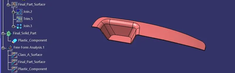
Draft_analysis for Pastic_Component:
The final plastic component is going under the draft analysis in the same procedure which was used for the class_A_surface.
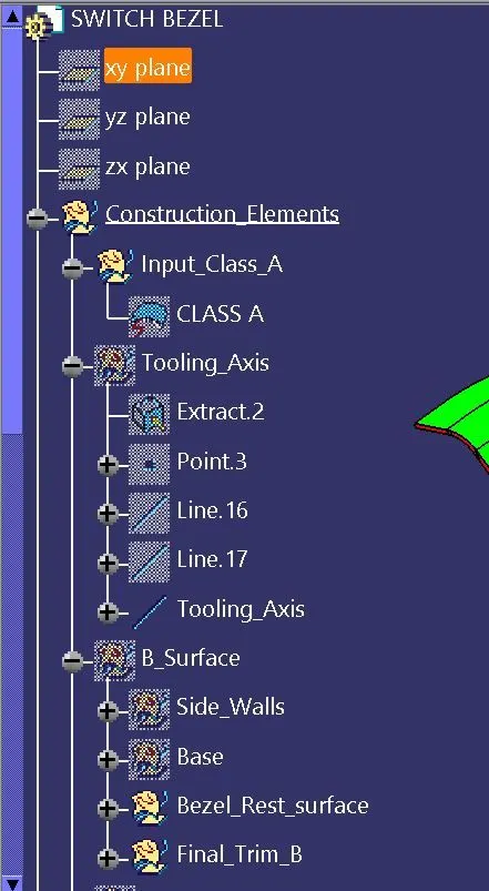
Tree_Structure:
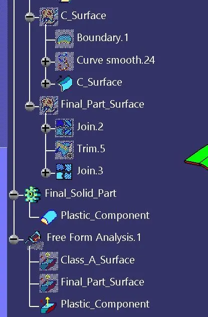
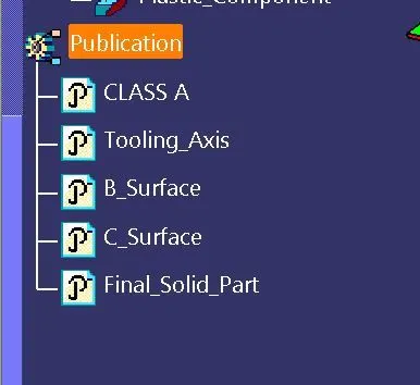
Solid_Part_with various_orientations:
Front View:
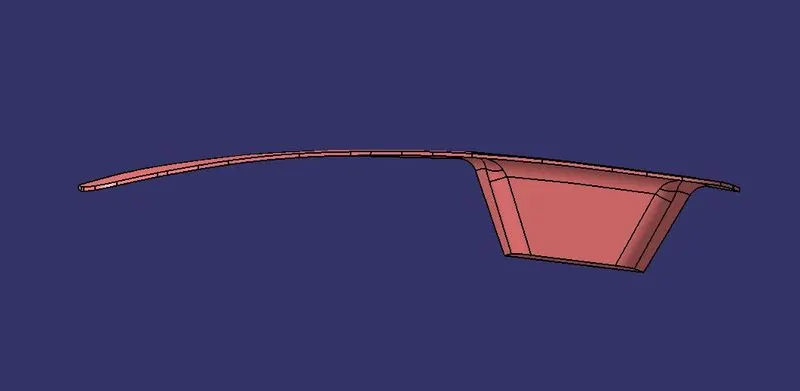
Top View:
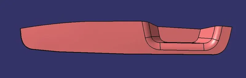
Side View:
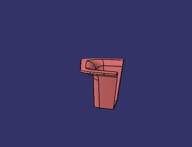
Isometric View: