Week 9 - Challenge 2 - Switch Bezel Design
AIM:
Create the Switch Bezel Plastic component through the given Class-A surface. To begin with, the tooling axis for the given Class-A Surface should be created meeting the requirements of the draft angle and at the end perform the Draft analysis on the model.
Take the Thickness of the component to be 2.5 mm
INTRODUCTION:
Switch Bezels in car are parts which contains switches and controls for different functions like Window control, Door lock/Unlock,Media and Temperature controls.
PROCEDURE TO CREATE SWITCH BEZEL COMPONENT:
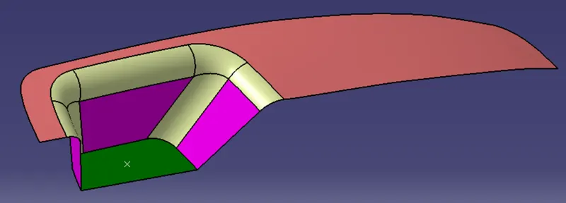
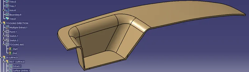
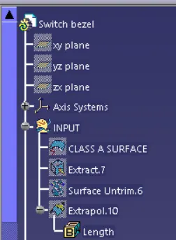
STEP 1: CLASS A SURFACE
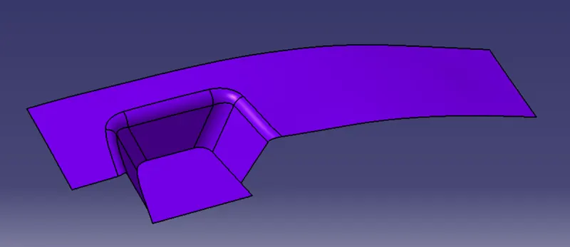
The above is the given class A surface.
Take the surface and insert in the separate geometric set.
Publish the Class A surface for Easy use.
STEP 2: TOOLING AXIS
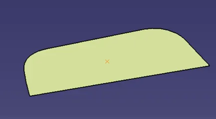
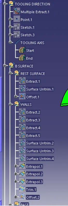
1.Create the point on centre of the extracted surface.
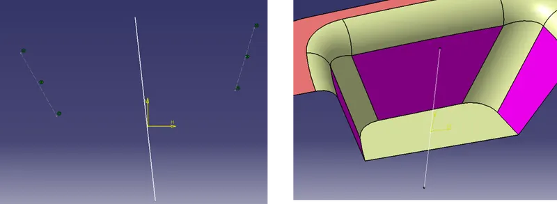
2.Create the bisect line from two side surfaces.
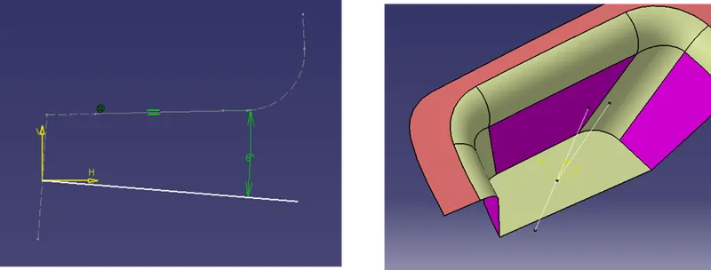
3.Create the line angle to the single side surface as shown in figure.
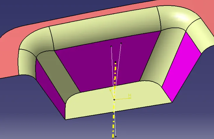
4.Create the bisect line from the two surface lines and create the line, which is the Tooling axis as shown in yellow colour.
STEP 3: B SURFACE CREATION
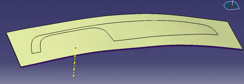
1.REST SURFACE
Extract, untrim and offset (2.5mm) the rest surface as shown in figure.
2.SIDE WALLS
Extract, untrim, Extrapolate and offset (2.5mm) the side wall surfaces as shown in figure.
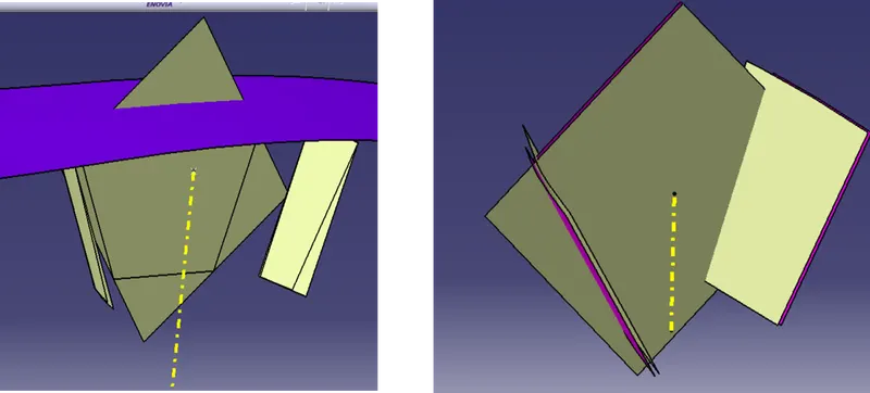
3.BASE SURFACE
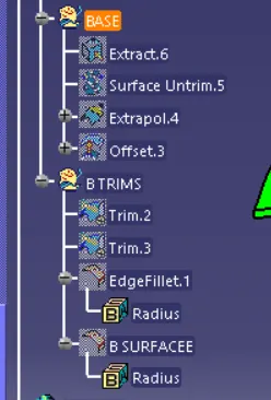
Extract, untrim, Extrapolate and offset (2.5mm) the base surface as shown in figure.
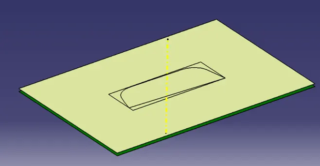
TRIMMED B SURFACE:
Trim the B surfaces and add the edge fillets to the edges, we now get the B surface.
STEP 4: C SURFACE CREATION
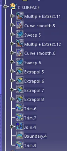
1.Extract and smoothen the bondaries
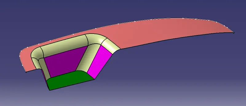
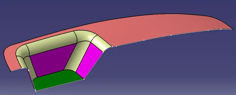
Extract the boundaries from A surface to create the C surface
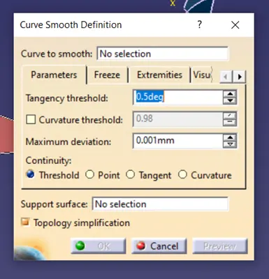
Smoothen the curve using the smooth curve option to get the non patchy and smooth surface.
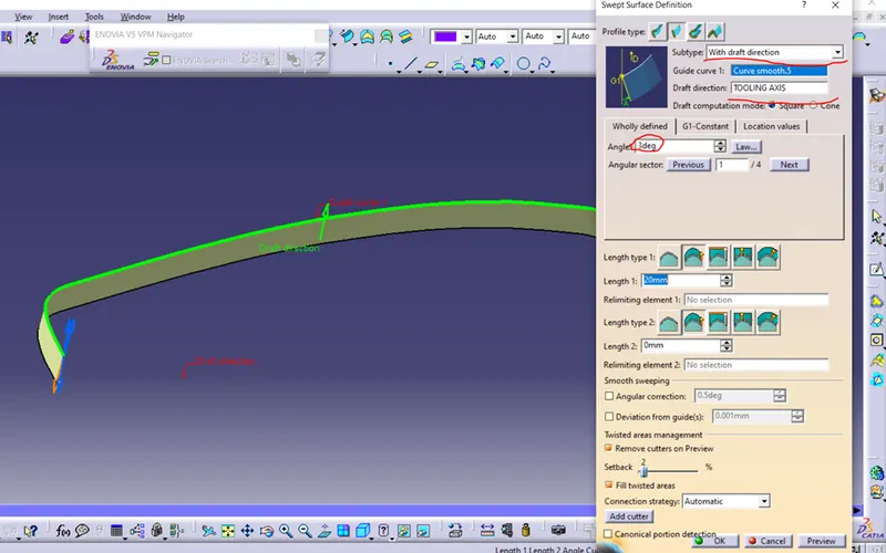
2.Sweep Creation
Select the boundaries, select along draft direction and tooling axis as draft direction, give the angle of 3 degree, and ensure the draft inward or outward using the arrow.
Extrapolate and trim the sweeped surfaces
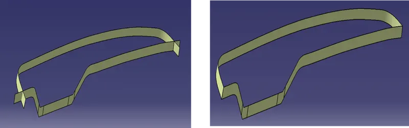
2.Join A and C surface
Join the A and C surfaces and trim to get the join surface
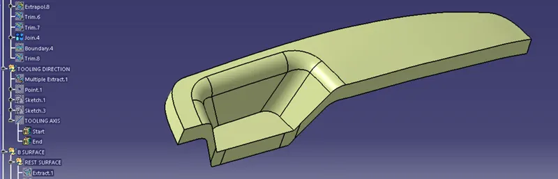
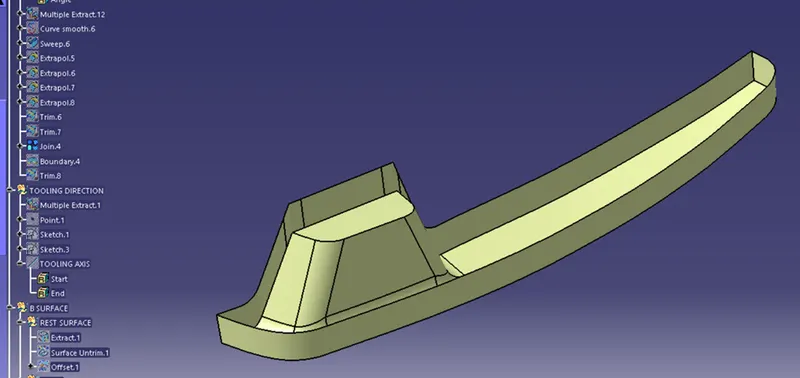
STEP 5: FINAL TRIM OF C SURFACE
Trim the B surface with the join surface to get the final C surface.
STEP 6: CLOSED SURFACE
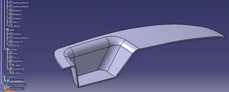
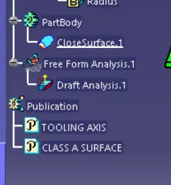
Go to part design, create the closed surface, select the final trim surfaces.
FINAL CLOSED SURFACE:
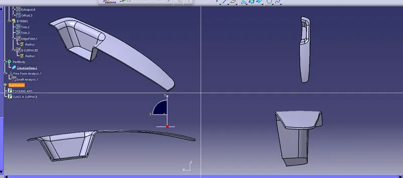
Multi View of final component:
STEP 7: DRAFT ANALYSIS
DRAFT ANALYSIS:
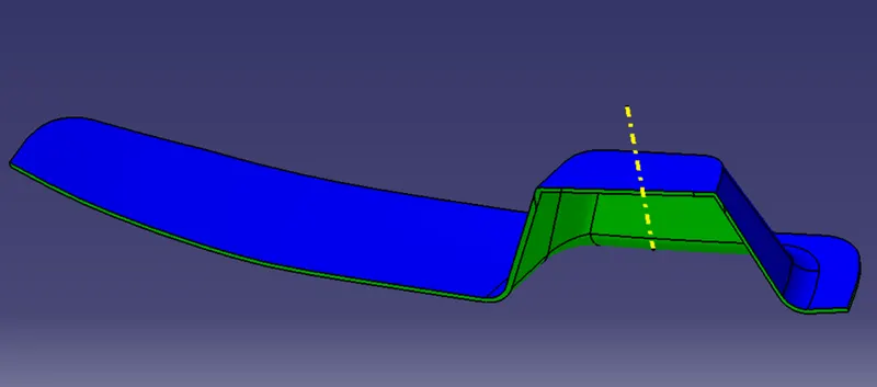
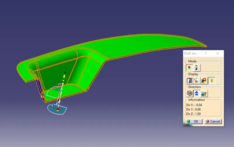
Draft analysis was carried out by switching to MATERIAL view.
Finally draft analysis is done for the closed surface part,
drag the compass to the tooling axis and
touch the surface of the part to get the draft analysis result.
The value was changed to 2.9degree and the part turned into green
It shows the green colour all over the surfaces,It says that the part designed is able to manufacture.
TREE STRUCTURE:
CONCLUSION:
The Switch Bezel part is created with wall thickness of 2.mm using the given A surface and Draft Analysis is done to check the tooling.
The part created is attached.