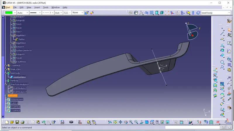
Week 9 - Challenge 2 - Switch Bezel Design
CLASS A DRAFT ANALYSIS :
Checking continuity of given class A surface:
we have to check the continuity of the given class A surface to ensure type A character is properly joined or that no discontinuity is present. This can be done using the join or boundary command in CATIA.
Draft analysis:
1) To perform draft analysis. Go to insert < Analysis< Feature draft analysis.
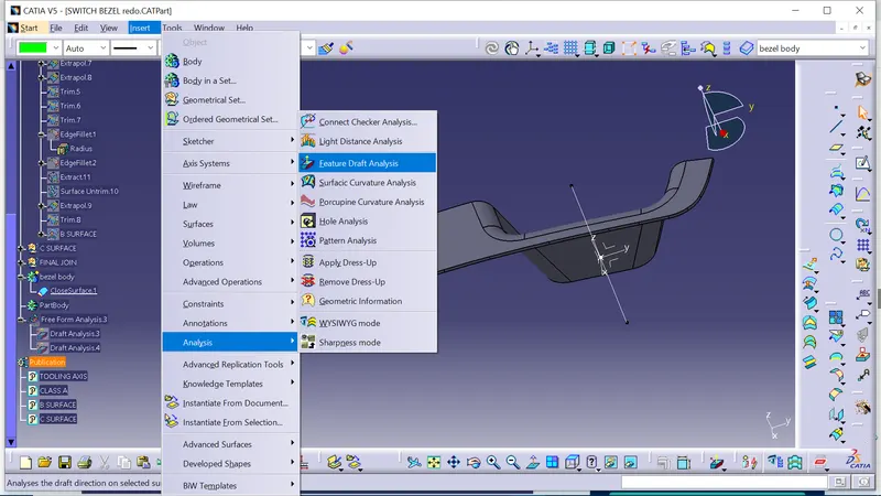
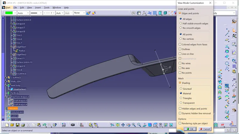
2) Before that switch customize view parameter mode to the material.
3) Click on the compass icon & align it with the tooling axis & click on the surface, we will get our results.
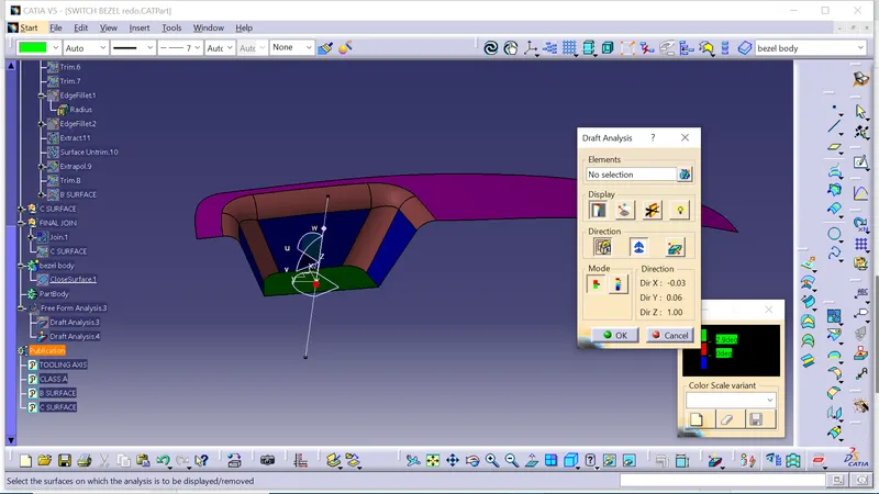
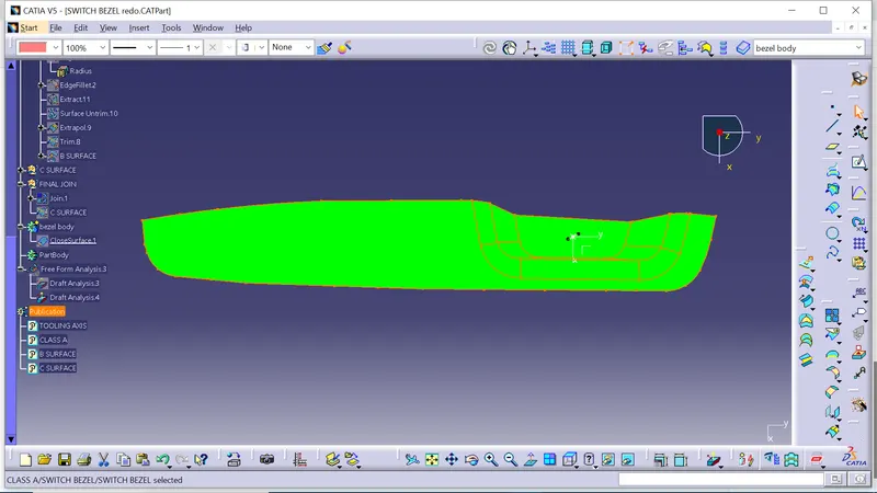
AFTER DRAFT ANALYSIS
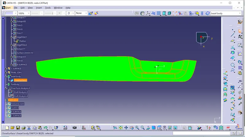
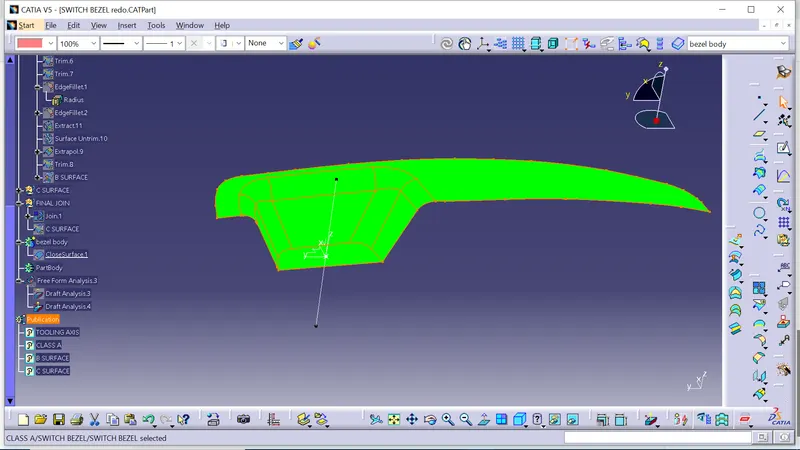 From the above image it is seen that surface in green colour has within 3° draft which is most required for tooling feasibility.
ISOMETRIC VIEW
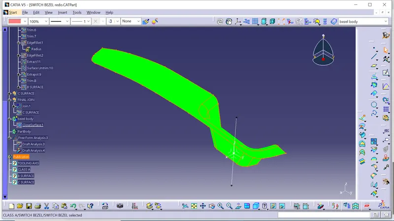
FRONT VIEW
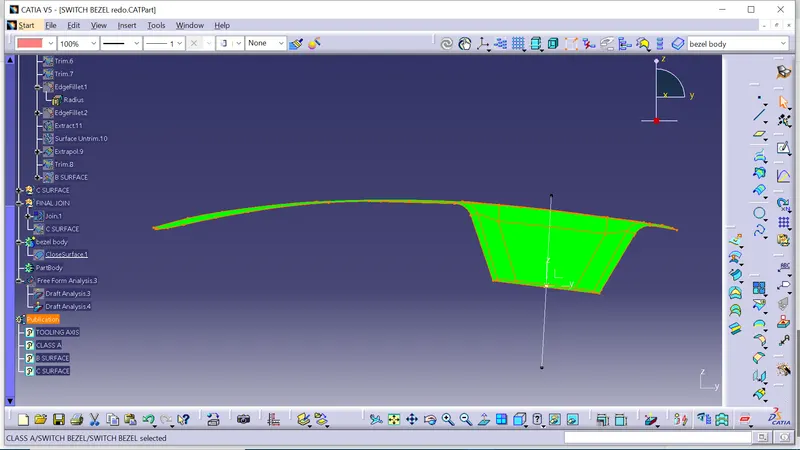
SIDE VIEW
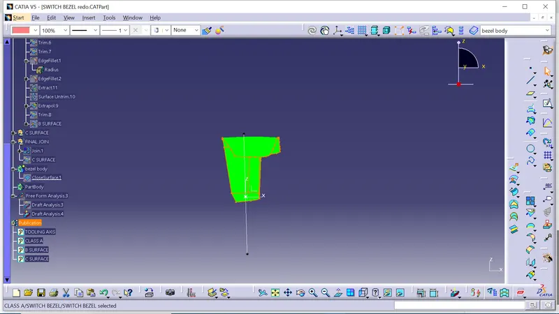
TOP VIEW
FINAL PLASTIC COMPONENT
Tooling axis direction:
The next step is to decide the tooling axis direction. The tooling axis is the direction in which the mould or core & cavity open. Analyzing the model visually to see which direction is most suitable for the tooling axis. From the below image, it is clearly seen that the surface has a hole at its top & cutout at the sides.
Now we have to see which surface will create problems or will be difficult for tooling. Because the surface which is 90° to the tooling axis will be cleared. So we have to check the surface which lies parallel to the tooling axis direction. Make lines along parallel surfaces using point-to-point direction. Here we get two lines, now we will bisect the two lines & choose a vertical direction. This will be our tooling axis for X – the direction.
Determine Tooling Axis:
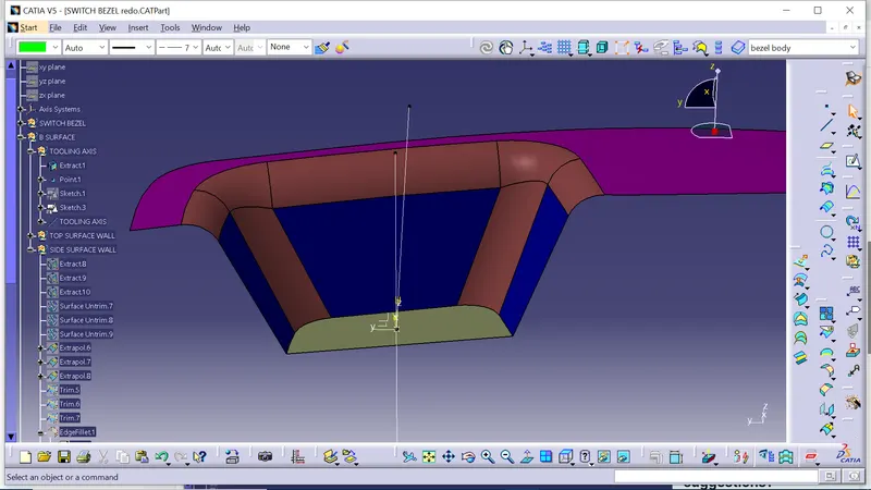
Extract the base surface of the Switch Bezel and place a point in between the Surface > Point definition select surface > Distance = 0mm and place an Axis system on that point.
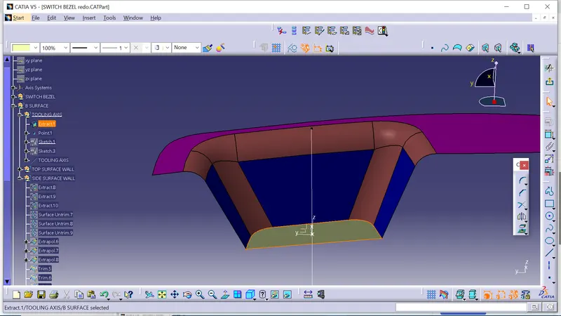 Now using the axis system and the point create a sketch for the tooling axis along the Y direction.
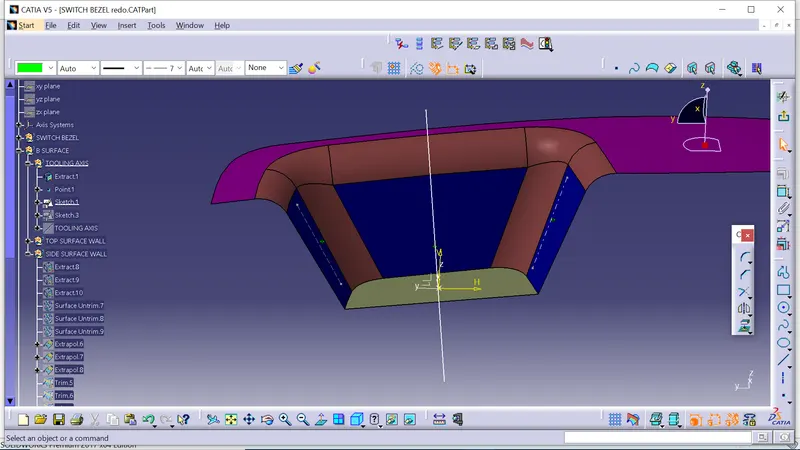 Using the same method we will also create the tooling for X direction.
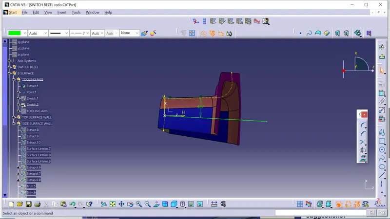
Now that we have achieved the tooling axis for the X and Y directions we will use these two tooling axis to create the main Tooling Axis i.e. along the Z direction by bisecting the X and Y direction lines.
DRAFT ANALYSIS:
Go to INSERT > ANALYSIS > FEATURE DRAFT ANALYSIS and move the compass to the Tooling Axis. Change the range to 3°
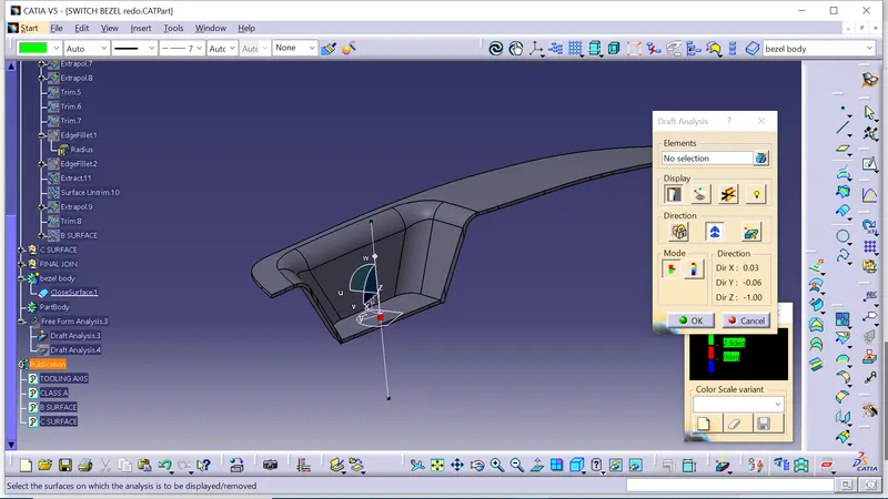
2. The Draft Analysis of the Switch Bezel Body is shown below the Component is safe.
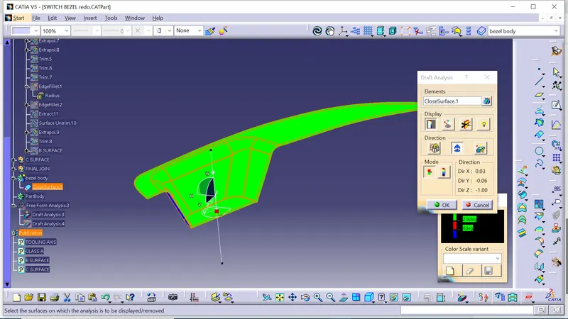
ISOMETRIC VIEW
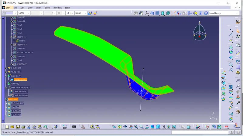
FRONT VIEW
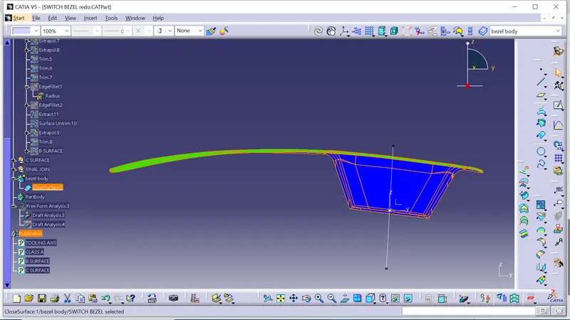
SIDE VIEW
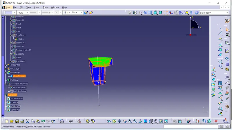
TOP VIEW
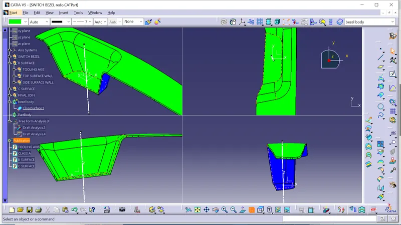
CLOSE SURFACE: