Week 9 - Challenge 1 - Base Bracket Design
CLASS A SURFACE DRAFT ANALYSIS:
Draft Analysis:
Draft analysis is done after determining the tooling axis, draft analysis is used to check whether the minimum draft (3 degrees) is maintained.
A compass is used to define the draft direction.
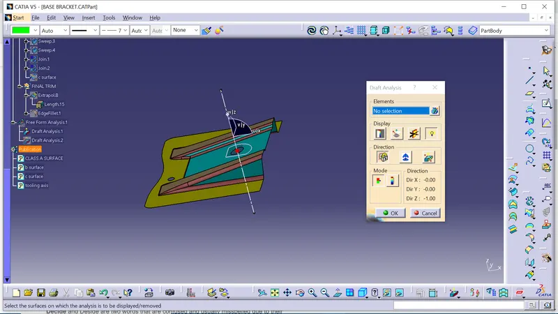
Lock the direction of the compass ,In display colour scale to be selected and pick the red cursor point on class A surface it would turn into green. green colour indicates the draft angle is within 3 degree, red colour indicates 0 degrees, and blue colour indicates a negative draft angle.press ok to complete analysis.
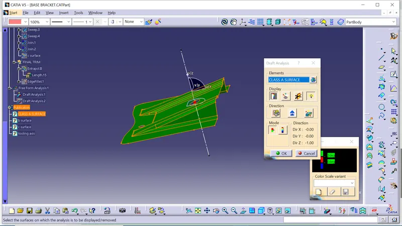
ISOMETRIC VIEW:
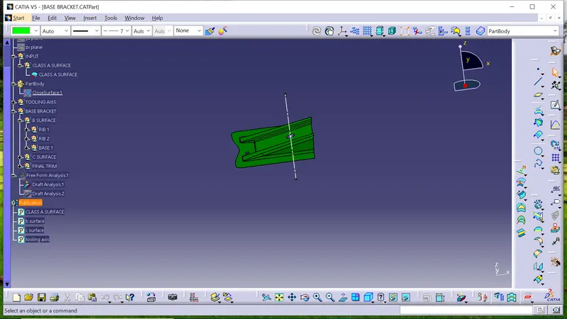
FRONT VIEW:
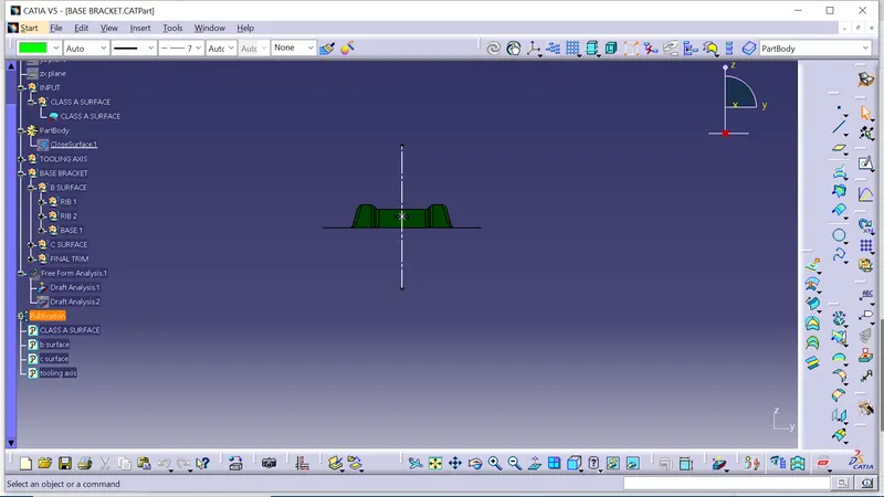
TOP VIEW
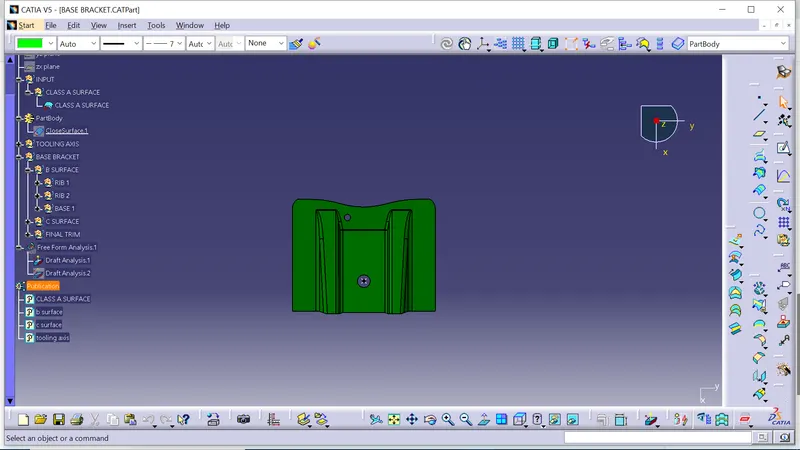
SIDE VIEW
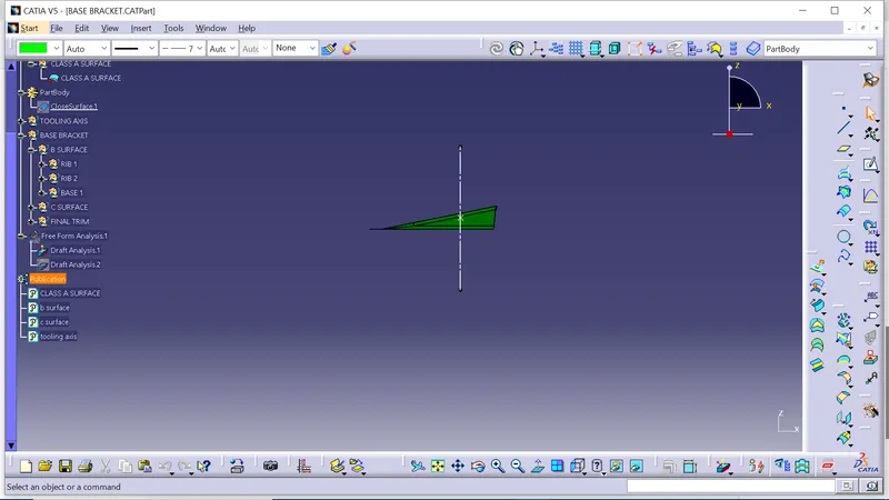
FINAL PLASTIC PART:
Draft analysis:
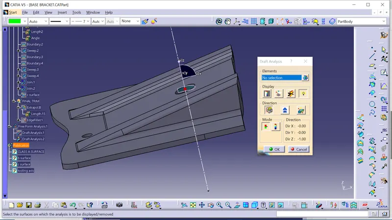
after draft analaysis

ISOMETRIC VIEW
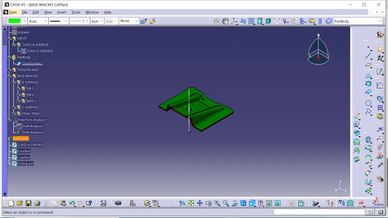
FRONT VIEW
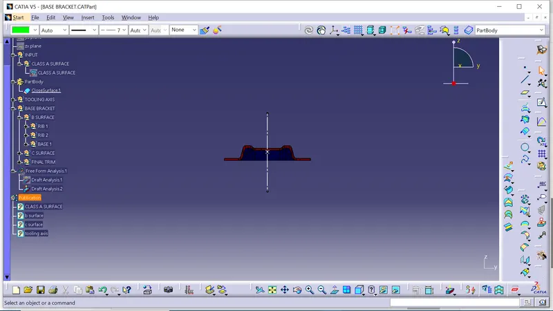
SIDE VIEW
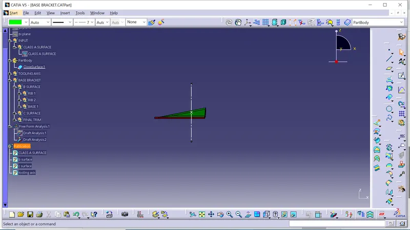
TOP VIEW
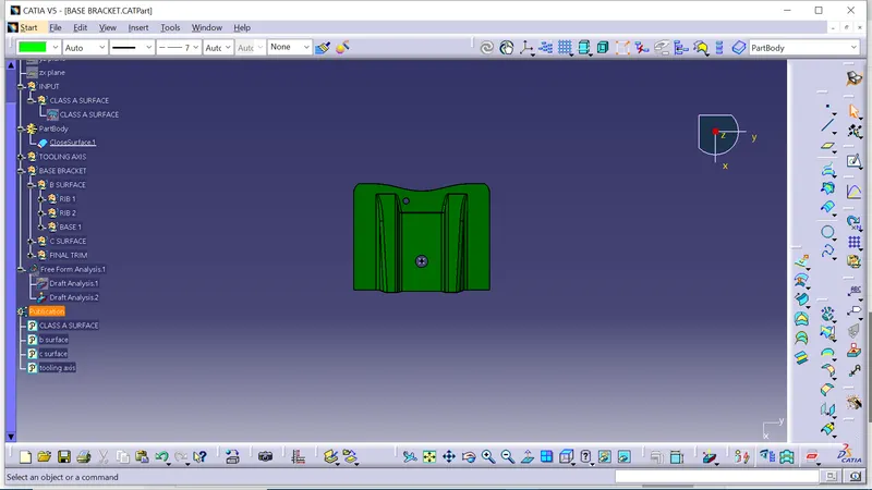
TOOLING AXIS :
purpose:
The tooling axis is required to determine the tooling direction which side core and cavity to be designed.
How to create the tooling:
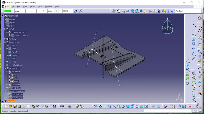
After interpretation of class, A surface tooling postion of tooling axis and tooling direction is decided.In the given model two holes have been provided I have selected one hole for positioning of the the tooling axis it would be easy for the manufacturing process for selecting references and further any correction would be easy.
the first step is to create a dummy tooling axis so to create a line point definition command is used
Creating intersection and Tooling axis :
Using the intersection, lines will be created along the inclined walls, these lines are used for the creation of the tooling axis by a bisecting method where the two lines and point will be selected as inputs the line will be created will be the final tooling axis
Tooling axis uses in this model:
I used the tooling axis while creating the c surface for sweep command and draft analysis.