Week 9 - Challenge 2 - Switch Bezel Design
OBJECTIVE :
To Create the Base Bracket Plastic component through the given Class-A surface. To begin with, the tooling axis for the given Class-A Surface should be created meeting the requirements of the draft angle and at the end perform the Draft analysis on the model.
TOOLING AXIS:
We should observe and study the class A surface to create the 'Tooling Axis' for the component, for the above-given base bracket Z-axis is the best suitable tooling axis. Initially, I created a Tooling axis and dummy tooling axis on Z-axis by considering the reference point created in the middle of the circle.
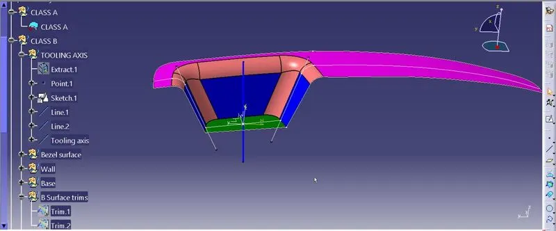
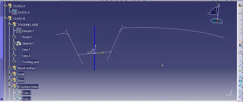
Create the axis point and draw the tooling axis using bisetting.
CREATION OF CLASS B :
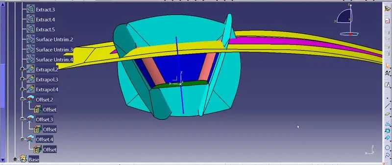
- If we directly offset the class A surface, fillets may lead to cause an error, to avoid the errors we need to extract the surfaces and untrim the extracted surfaces and extrapolate those untrimmed surfaces with point continuity.
- Now for Class B creation, we have extracted surface from Class A and untrimmed them to obtain the original parent surface.
- These surfaces are then offset to the required thickness of 2.5mm.
- After offsetting, all the surfaces are trimmed into the required shape.
- Required fillets are given to the surfaces.
BEZEL SURFACE+WALL+BASE :
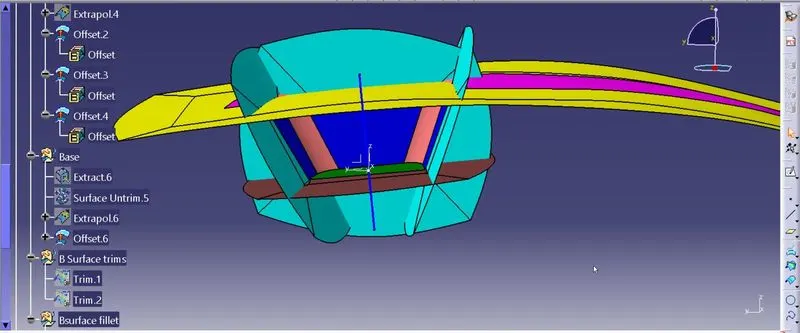
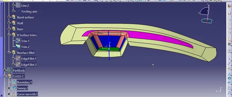
CLASS C SURFACE
It is the combination of Class A, Class B and Class C surfaces. To create a class C surface, I have used the sweep command by considering the outer boundary of the class A surface. In this sweep command, go to the 'line' command in the 'profile' block and the subtype is 'with draft direction'.
Now, select the outer boundary and tooling axis, give 3 deg in the angle (the draft angle for a plastic component is 0.5 to 3 deg) and select the direction to sweep, in this condition the class B surface is under the class A surface.
So, select the inside down arrow to sweep. The same procedure is repeated for the two circles on the class A surface. Now I joined all the sweeped surfaces by using the 'JOIN' command and then I trimmed the Class A, Class B and Class C surfaces to make a closed surface, to make a Solid body.
SWEEP TOOL :
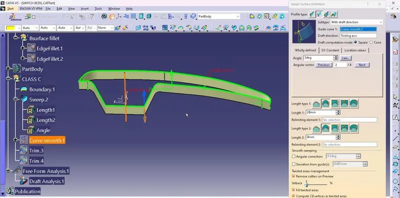
FINAL TRIMS
CLASS A+B+C
To make sure that there is not any open boundry between class A and class C, we have used join option to created the single body. This is done to make sure that the parting line doesn't lie between the these two surfaces.
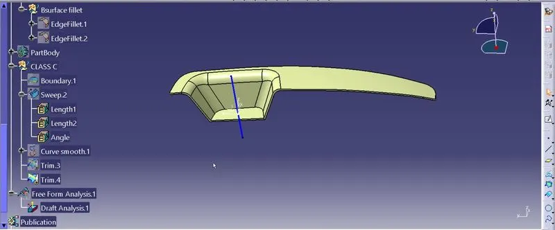
SOLID BODY :
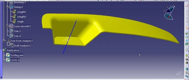
DRAFT ANALYSIS
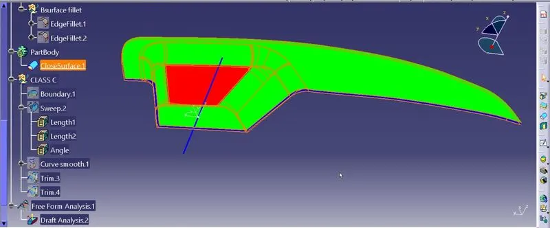
Once the draft analysis toolbar is opened, go to the display block and select the 'Analysis under the running point' command to check the angle for different sides (ribs and inclined plane angles) on the class A surface. The color scale on the bottom visualizes, whether the draft angle meets the requirements or not (3 deg) by indicating the colors Green, Blue and Red. Once the draft angle analysis was done, we need to align and fix the compass to the tooling axis of the class A surface.
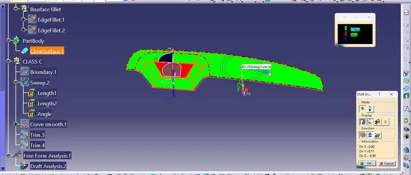
To align and fix the compass to the tooling axis, go to the Direction block in the draft analysis toolbar and click on the 'Use the compass to define the new current draft direction option (or just click on the compass symbol). Now bring the compass to the surface and align it to the tooling axis of the class A surface and click on the lock symbol beside the compass in the direction block. Once we click on 'ok' on the draft analysis toolbar, we can finish the draft analysis process.