Week 9 - Challenge 2 - Switch Bezel Design
AIM
Create the Switch Bezel Plastic component through the given Class-A surface. To begin with, the tooling axis for the given Class-A Surface should be created meeting the requirements of the draft angle and at the end perform the Draft analysis on the model.
Take the Thickness of the component to be 2.5 mm
DESIGNING OF SWITCH BEZEL
TOOLING AXIS FOR GIVEN CLASS A SURFACE
First create a tooling axis for the given class A surface .In this direction the mold opens and closes .So the tooling axis should be selected in the proper direction.
here z axis is consider as the tooling direction.Then create the tooling axis clearing X and tooling axis clearing Y direction .Using this two lines to create a bisecting line .This bisecting line consider as the is the main tooling axis.
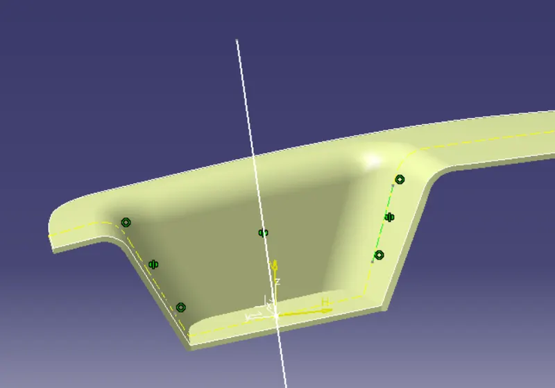
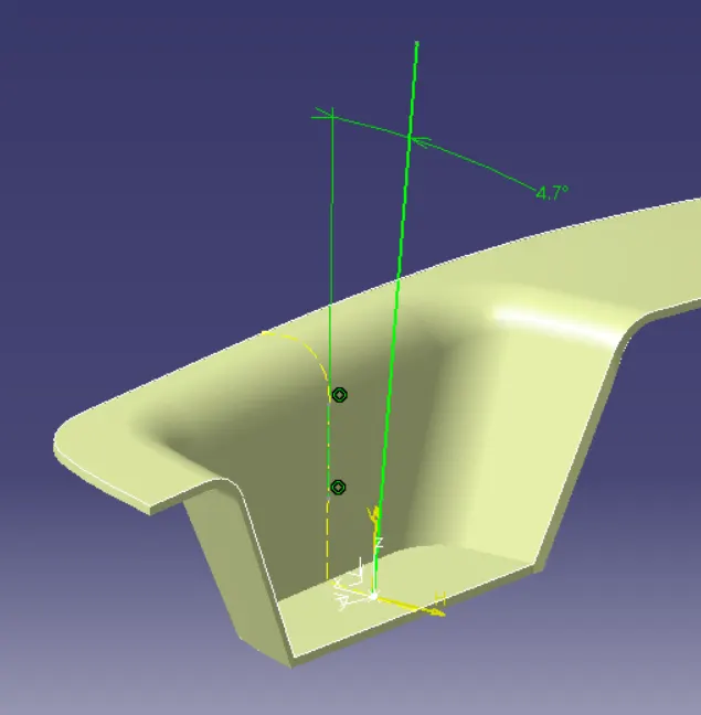
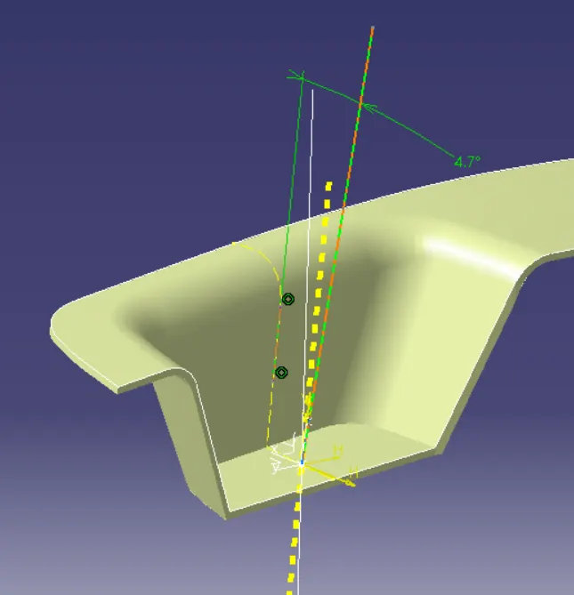
DRAFT ANALYSIS OF CLASS A SURFACE
Check the draft analysis of the given class A surface along the tooling direction to ensure the part has minimum draft angle (3 degree) in all faces.
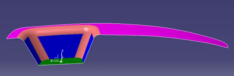
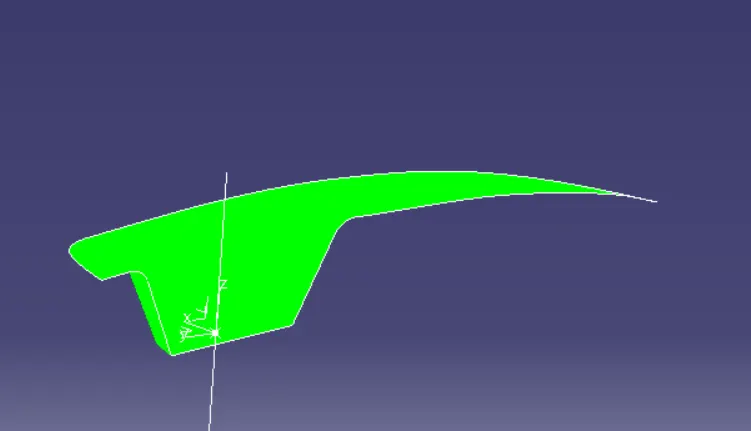
fig-draft analysis of class A surface.
CLASS B SURFACE
Class b surface created from the class A surface .Extract the required surfaces from the class A surface , untrim ,extrapolate and offset in to required thickness .finally trim this surfaces to get the class B surface .Error-free fillet value should be given to the edges.
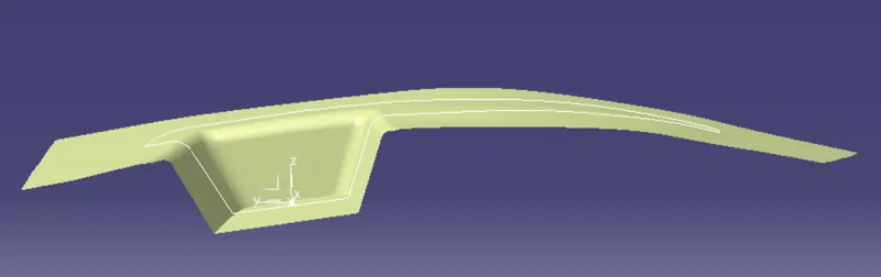
CLASS C SURFACE
Class C surface connecting the class A and B surfaces.Extracting the boundary of class A surface and using the swept with draft direction to create the class C surface.
1.Then join the class A surface with class C surface (use smoothening curve option if any trouble found affter joining the surfaces )
2.Finally trim with class B to get the closed surface of switch bezel .
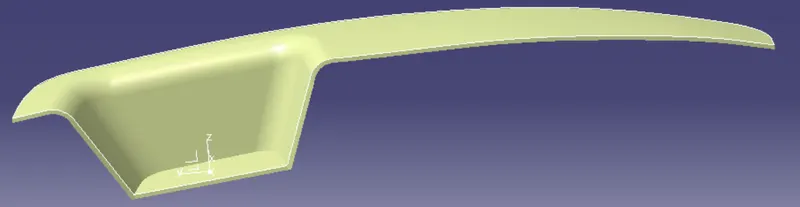
DRAFT ANALYSIS OF FINAL SOLID BODY AND DIFFERENT VIEWS
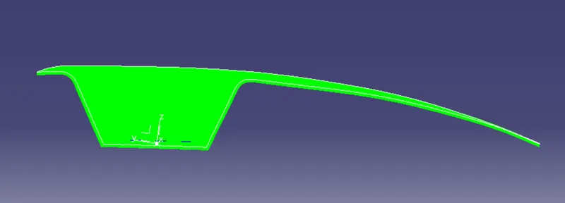
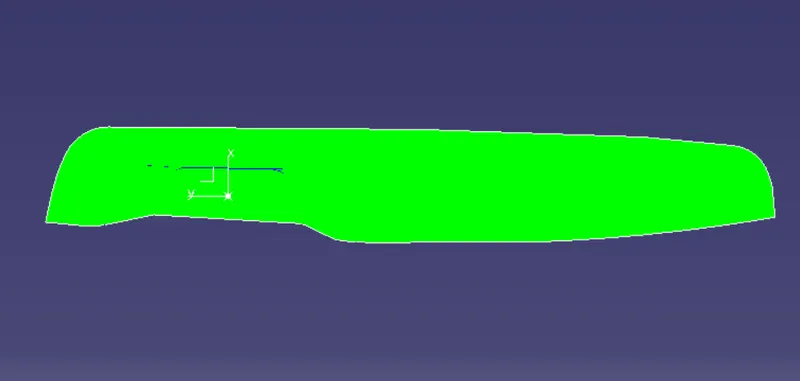
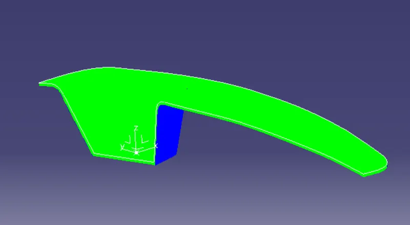
Use the draft analysis to check the final product has minimum draft angle.here all the surface has draft angle above 2.9 degree
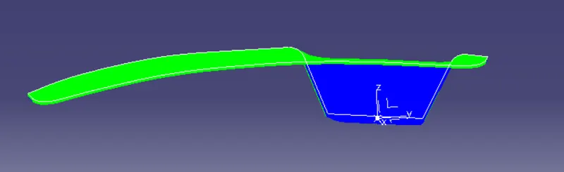
CONCLUSION
Switch Bezel Plastic component created using the given Class-A surface. draft analysis performed on the model