Week 9 - Challenge 2 - Switch Bezel Design
AIM:
To construct the Switch bezel plastic component with the given glass surface.
METHODS:
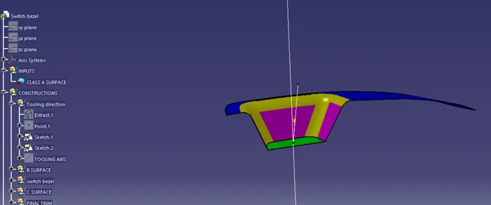
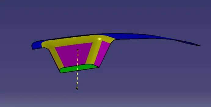
- The methods below demonstrate how to use the necessary tooling axes to acquire the correct draught analysis.
- Although this component has a single hole from which the tooling axis can be produced, it lacks the necessary four walls to accomplish so. In this instance, a rough estimate is used to determine the tooling axis.
- The first step is to create a false axis using the two side walls. Given that the draught angle is 3 degrees, the second axis is chosen to be 3 degrees from the specified wall, and the tooling axis is created using these two axes.
CREATION OF TOOLING DIRECTION:
CREATION OF B SURFACE:
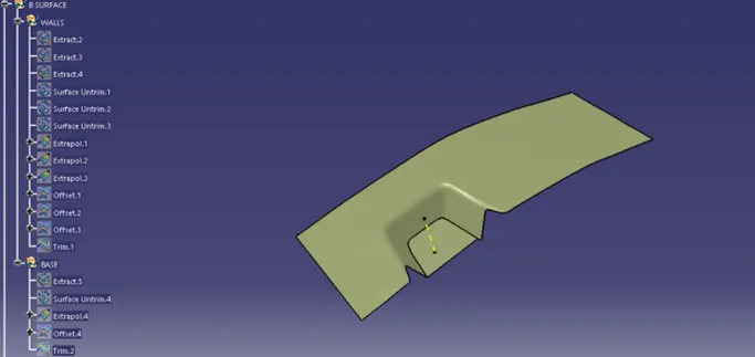
The B surface is created by extracting the required faces,
- Extracting the faces and trimming the unwanted faces.
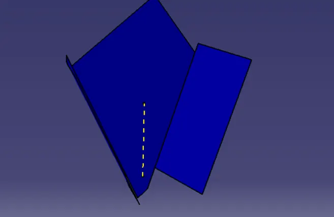
BASE;
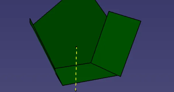
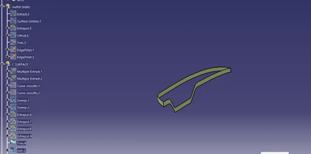
SWITCH BEZEL;
C SURFACE;
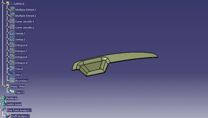
FINAL TRIM (CLASS A + B + C):
CLOSED SURFACE:
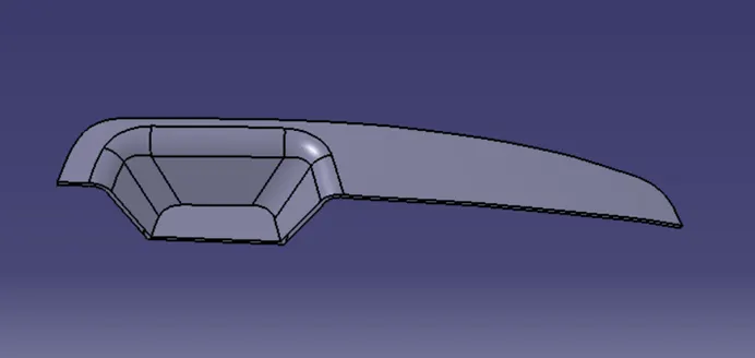
DRAFT ANALYSIS:
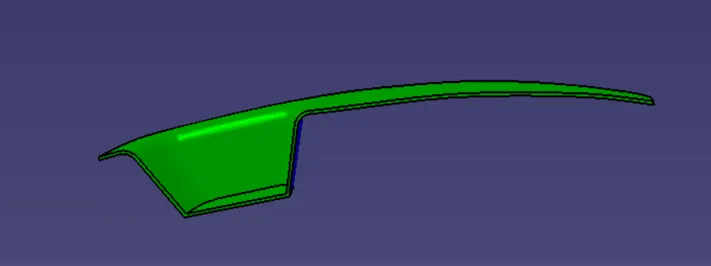
TREE STRUCTURE:
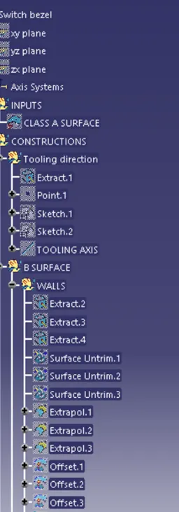
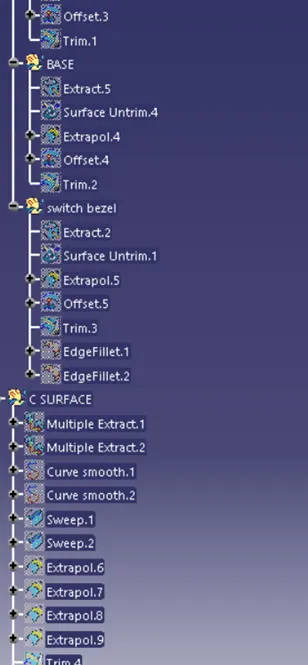
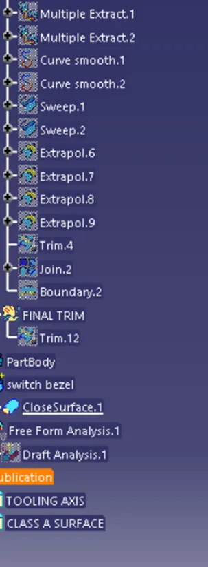
PART ZIP FILES:
CONCLUSION:
Switch bezel design is successfully completed using Given class A surface.