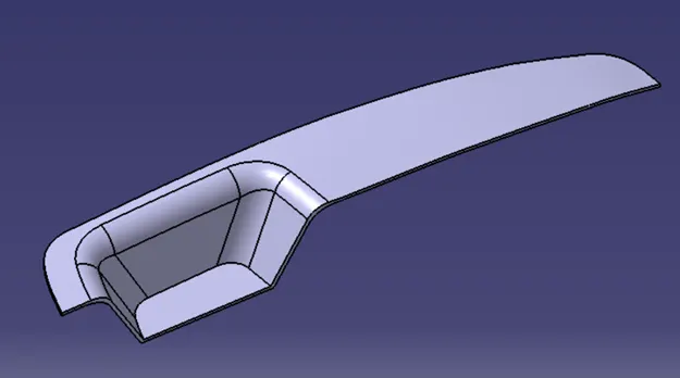
Week 9 - Challenge 2 - Switch Bezel Design
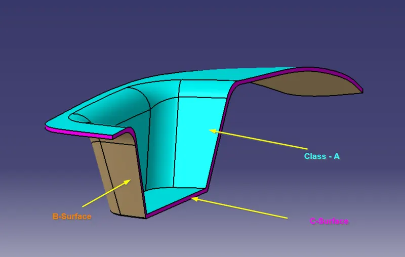
Create the Switch Bezel Plastic component through the given Class-A surface. To begin with, the tooling axis for the given Class-A Surface should be created meeting the requirements of the draft angle and at the end perform the Draft analysis on the model.
Take the Thickness of the component to be 2.5 mm
Input File Extensions:
Switch Bezel ,CATPART
Switch Bezel .IGES PART
Switch Bezel .STP FILE
Use .STP extension file.
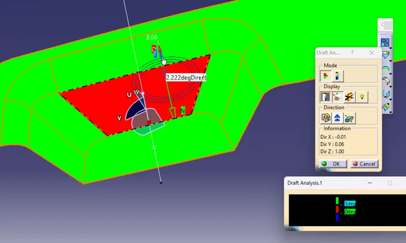
Draft analysis :
Red Color Slant Surface Angle is 2.22Degree. We increased the y axis angle by 2 degree,
which will result in minimum 3 degree draft angle.
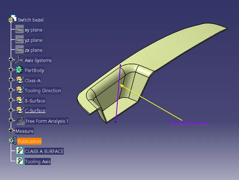
Tooling Direction :
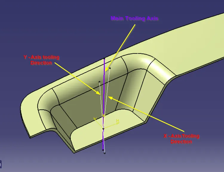
To define tooling direction for this part, need to consider both X – direction surfaces as well as Y – axis.
Create a center point at the bottom of the pocket and add an axis system to intersect the surfaces in x- direction.
Bisect the slant curve to get the X- direction. Similarly, for y – direction.
The bisection line between X and Y will be the Tooling axis for this part.
Geometrical Set:
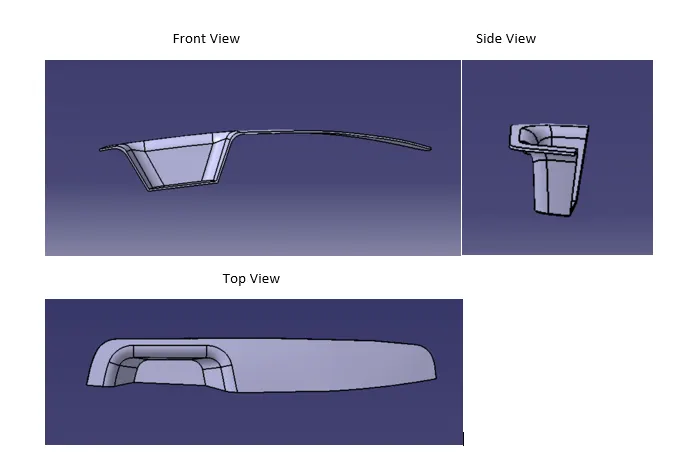
ISO View