Week -2
1) Simulink model of door bell using Solenoid block:
Simulink blocks used to create model:
- Pulse Generator(signal builder)
- Simulink-PS Converter
- Battery
- SPST Switch
- Solenoid
- Ideal Translation Motion Sensor
- Solver Configuration
- Mechanical Translation Reference
- Scope
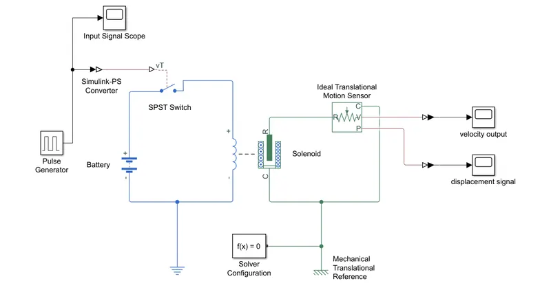
Condition :
Switch is closed for 2 sec and then relesed.
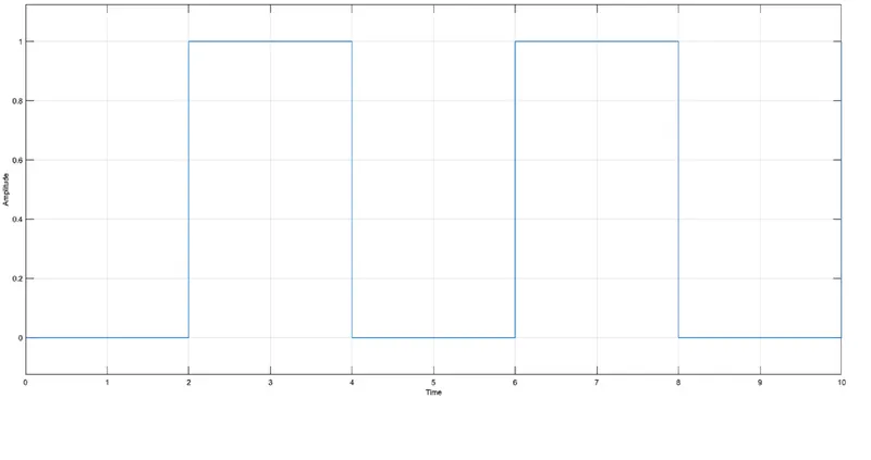
Theory:
To fullfill this requirement,
used signal builder block and sets the input signal.
Then used above mentioned blocks in proper sequence and for observe the results, added two scope.
Hit the run botton.
Results:
Graph 1:
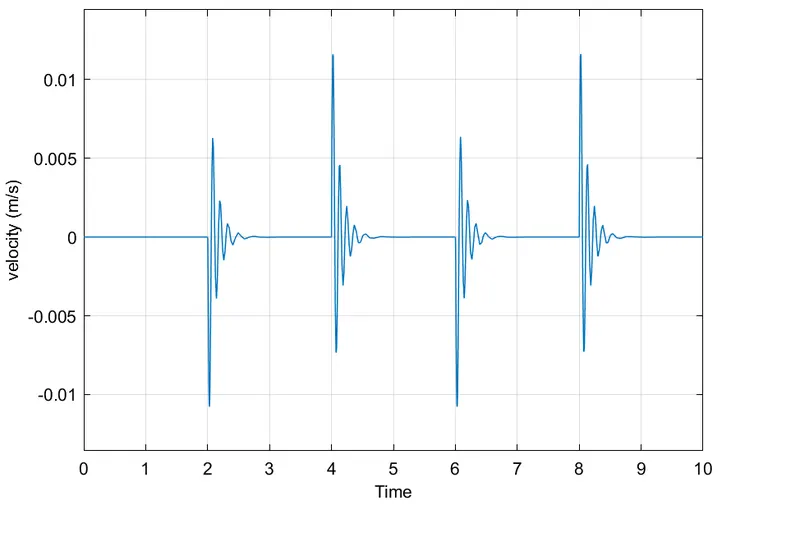
Above graph shows Velocity w.r.to Time
initially, for 0-2sec, graph follows straight line with zero velocity.
for 2-4sec, Change in velocity of the plunger in both the direction is observed.
again Same change observed for remaining 4-6 sec and 6-8sec.
Graph 2:
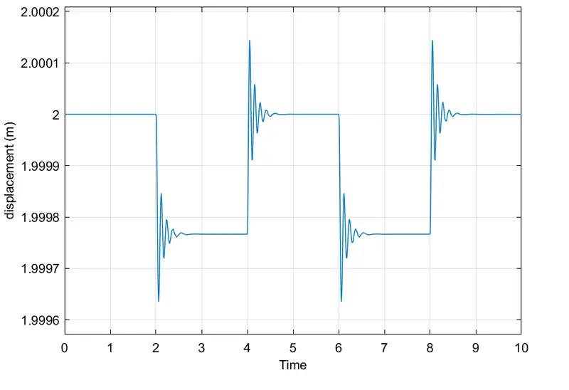
Graph shows Displacement v/s Time.
for 0-2 sec, core of solenoid is stationary.
for 2-4sec and 6-8sec, it shows displacement in down side. ie, plunger moves from rest position to forward direction.
for 4-6sec and 8-10sec, plunger moves at its initial position for 2sec.
Conclusion:
after Analyzing of the result, the bell is rang for 2seconds and ideal for 2seconds and continue for 10sec.
2) Use Thermister sensor to sense temperature of Heater and On or Off the fan occording to the condition:
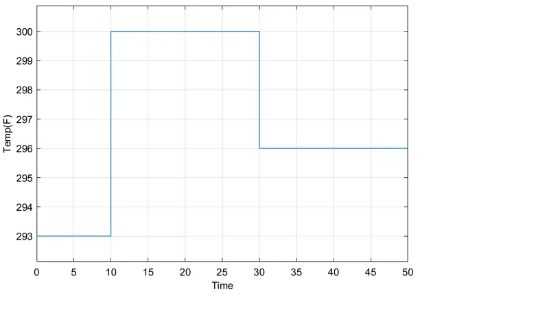
Temperature source: 20 °C from 0 to 10 seconds, 27 °C from 10 to 30 seconds, 23 °C from 30 to 50 seconds
Fan conditions: ON if the temperature above 25 °C, OFF otherwise.
Input Signal:
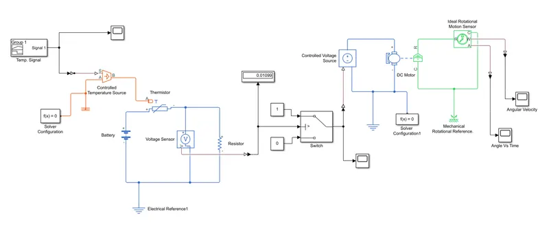
Simulink Model :
Block used and their function:
- Signal Builder - According to intial condition, Create the signal of temp.
- Simulink-PS Converter - Convert simulink signal to physical signal.
- Controlled temp source - Temperature generated at heater.
- Battery - Supply the required voltage.
- thermister -A thermistor is a thermally sensitive resistor that exhibits a precise and predictable change in resistance proportional to small changes in body temperature.
- Voltage Sensor - Sense voltage across the battery and thermister.
- Resister - Offers Resistance to current flowing in the circuit.
- Switch - When temp increases above 25 degree then it switch on the fan.
- Control Voltage Source - Voltage supply to run the motor.
- Solver Configuration - Solve the Equation of blocks.
- D-C Motor - It is attach to the fan.
- Ideal Rotational Motion Sensor- Sence the velocity of motor.
- Scope - show Results.
Result:
Speed v/s Time :
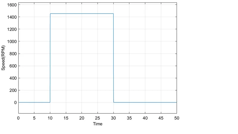
For 0-10 sec, temp is 20degree. Graph doesn't shows any change in speed.(fan off)
For 10-30sec, temp is 27 degree. Graph shows speed value in rpm and it continues to 30sec.(fan on)
For 30-50sec, temp is below 25 degree, ie. 23degree. Graph doesn't show any movement. (fan off)
Angular Displacement v/s Time:
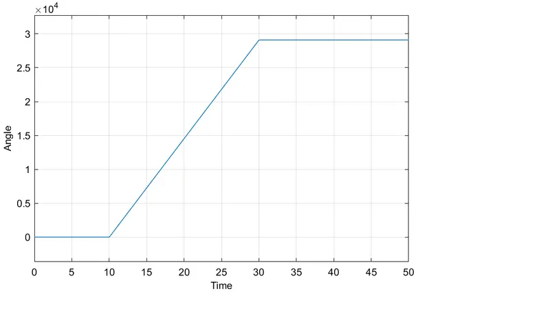
Graph shows angular displacement for 10-30 sec. Which means, motor is on only from 10-30 sec.
Conclusion:
After studying the obtained result data, the fan which is connected to the motor is on only when the temp raised above the 25 degree.
and remain off when temp is below 25 degree. Hence our purpose is fulfill.