Week 9 - Challenge 2 - Switch Bezel Design
Objective: The main objective of this challenge is to create a 3D solid body from the above-given class A surface, with the help of a tooling axis of the class A surface. Perform the draft analysis for the solid part body at the end.
Tooling Direction
- In Molding, machine arrangement is given to open the mould along a direction which is known as Tooling Direction.
- The mould is built from two separate halves (Core and Cavity) and tooling direction basically defines the direction of mould pulls apart.
- Tooling direction is known as primary direction.
PROCEDURE FOR CREATING THE TOOLING DIRECTION
- First, the given styling surface (class-A) imported into the generative shape workbench in CATIA and checked for irregularities by using Join or Boundary command. If there are no irregularities then it’s good to go or else the irregularities must be fixed first.
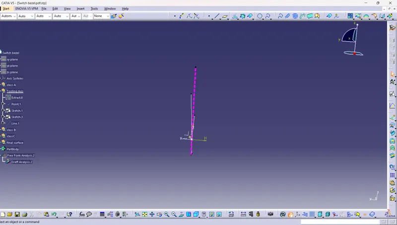
- Then the hole which is visible from the z-direction was taken into account and a point was created and by using it a line was created along the z-direction and named it a dummy tooling axis.
- Then by using the point axis system was inserted and by using the xz plane intersections were created on the class A surface.
- Then by using point to point line as shown in the below figure sidelines were created and by using the bisecting method the Tooling Direction was created and subjected to draft analysis.
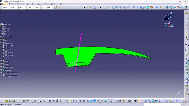
- By using the feature draft analysis tool the class A surface was analyzed for the created tooling axis with the compass locked to it. (Note: The Nominal draft angle is 3 degree for Plastic parts)
CLASS B SURFACE:
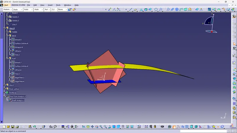
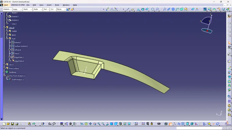
Class B is the offset of 2.5mm from the class A surface, but the fillets on the class A surface may lead to cause an error while we directly offset the class A surface. To overcome those errors I extracted the bezel rest surface, walls and base of the surface. Now, untrim those extracted surfaces and extrapolate to intersect planes with each other to get the same shape as a class-A surface by trimming those. now, I offset the trim to 2.5mm on the negative (below) side of the class A surface, after offsetting the trim give the fillets to the edges with the consideration of the thickness.
Bezel rest surface offset:
Fillet Measurement
CLASS C SURFACE:
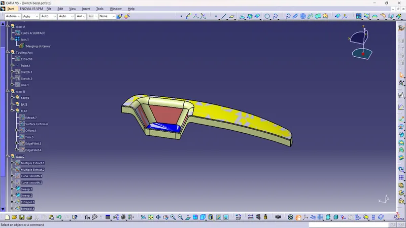
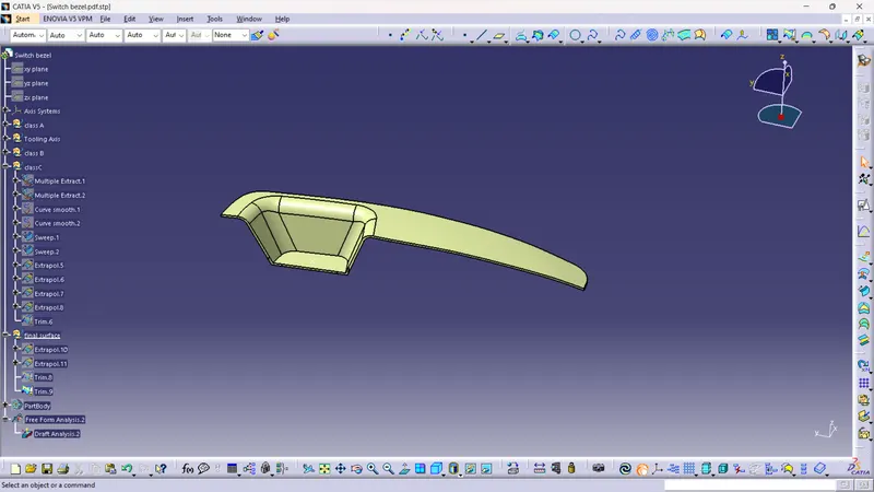
The class C surface is the combination of Class A and Class B surfaces. To create the class C surface, I extracted the boundary of the class A surface by using the multiple extract command. Now extended the class A surface boundary by using sweep command with 3 deg of draft angle. After I joined class A with an extended surface and then I trimmed that joined surface with class B surface to get a closed body.
Sweep command:
PART BODY:
After creating a closed body, we need to create a solid body from that closed surface. Now go to the part workbench to make the sloid body with the help of the closed surface command.
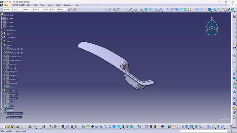
FRONT VIEW
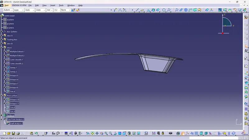
LEFT SIDE VIEW
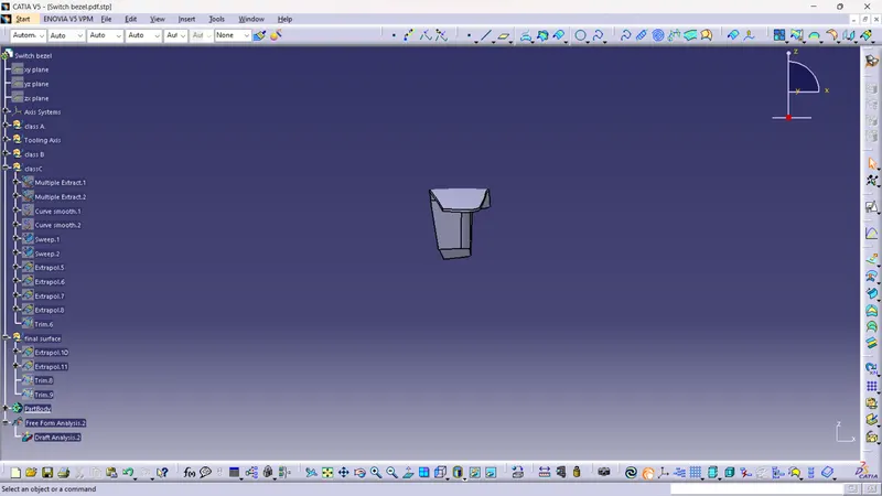
RIGHT SIDE VIEW
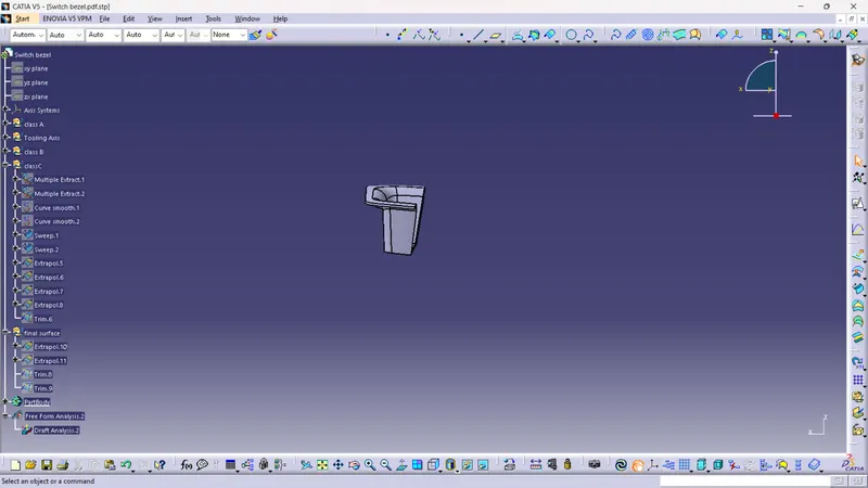
TOP VIEW
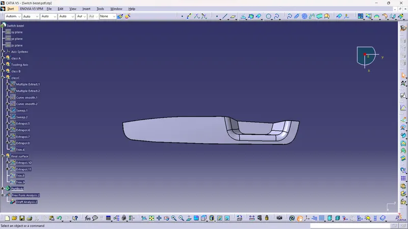
DRAFT ANALYSIS:
The draft analysis is done after the creation of the solid body by using the featured draft analysis command. Click on the compass symbol and align the compass to the tooling axis and give the color bar angle 2.9 deg, now check the color difference on the surface. If the surface is green color the draft angle is greater than 2.9deg (the green color limit is 2.9 deg), if the surface is red the draft angle is less than 0deg.
CONCLUSION
From the given class A surface the Class B and C surfaces for the Switch Bezel were created and by creating a tooling direction for manufacturing the Switch Bezel was analyzed and found successful