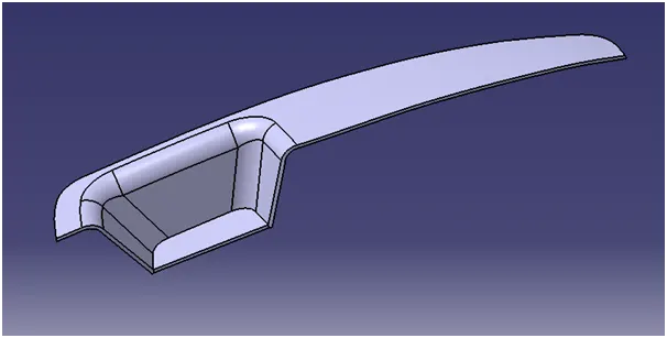
Week 9 - Challenge 2 - Switch Bezel Design
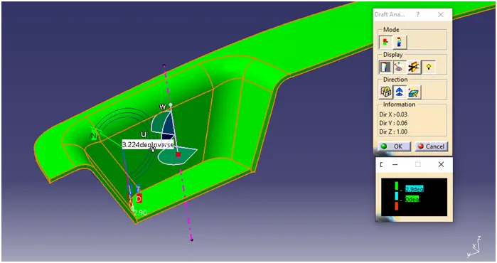
Challenge : Create the Switch Bezel Plastic component through the given Class-A surface. To begin with, the tooling axis for the given Class-A Surface should be created meeting the requirements of the draft angle and at the end perform the Draft analysis on the model.
Given Class A surface
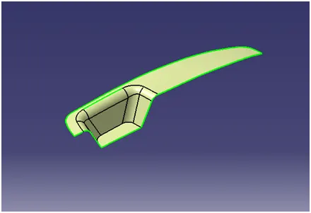
Colour provided to differentiate surfaces.
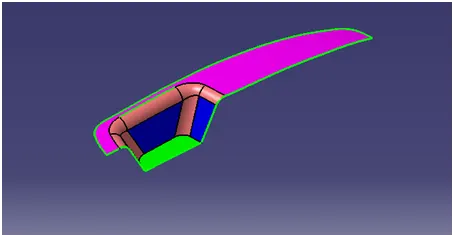
Draft analysis of given A surface
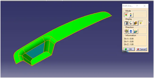
TOOLING DIRECTION
First extract the bottom surface and create a point in center.
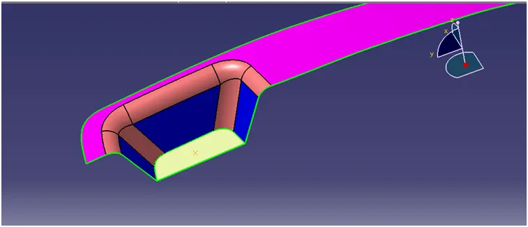
Tooling direction in Y direction.
Take an intersection on the class A surface in YZ plane using center point, create line on projected side walls lines and create bisecting line using the referance line created.
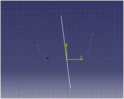
Tooling direction in X direction.
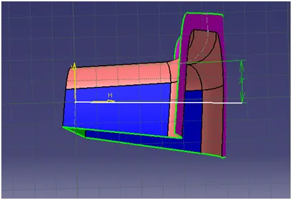
Create a sketch on ZX plane and take an intersection on class A, create a line on Z axis and provide the angle between the line & surface to 3o
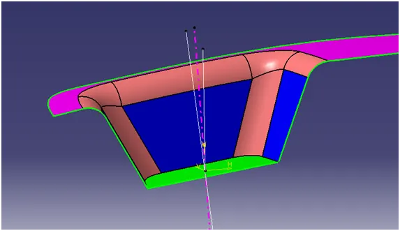
Create a main Tooling axis by creating a bisecting line using two lines.
Class B Surface.
Extract the top suface
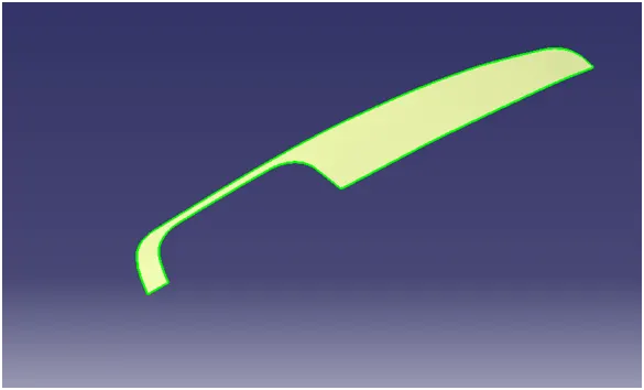
Untrim the surface & offset the surface for 2.5 mm thickness
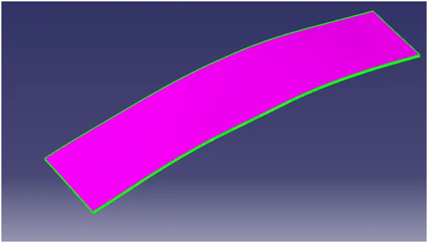
Extract the side walls and untrim the surface.
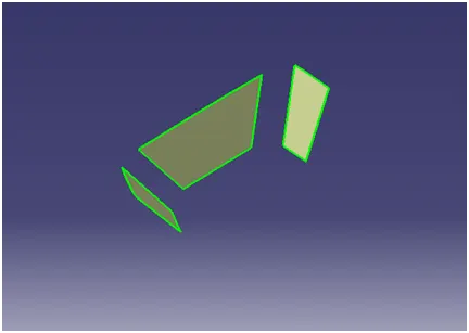
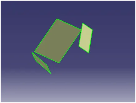
Extrapolate the surface, trim the unwanted surface & offset.
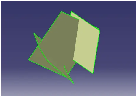
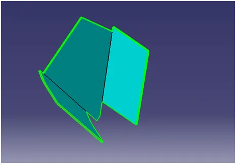
Extract the base surface, untrim, extrapolate & offset the surface
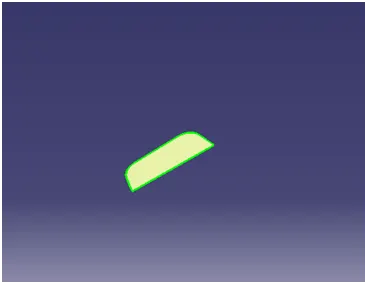

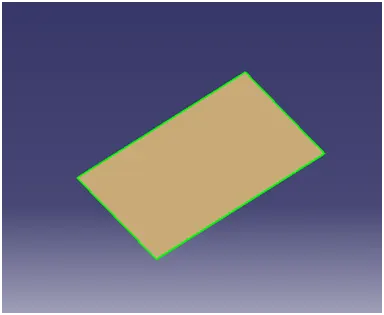
Trim the base surface with side & top surface.
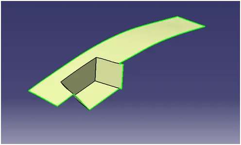
Class C surface
Create a sweep using boundry at back & front side seperatly
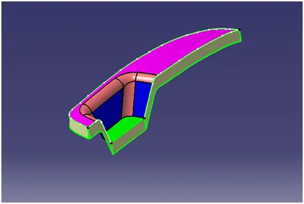
Extrapolate the edges to cover the gaps
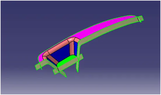
Trim the extended surface to form the C surface.
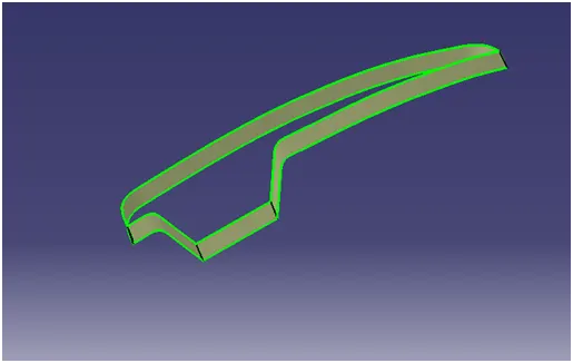
Join the B & C surface & extrapolate & trim if any boundaries found
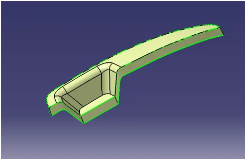
Trim the B,C with A surface to form the final output
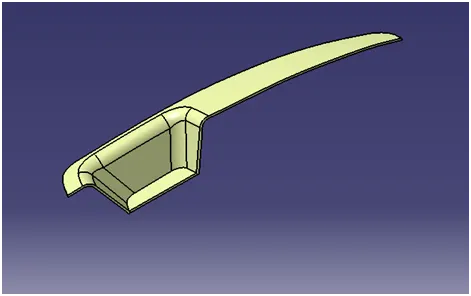
Draft analysis of final trim
Found draft valve less on one of the side walls having draft 2.22o
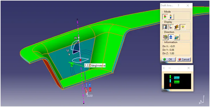
Than changed the X tooling direction to 5o
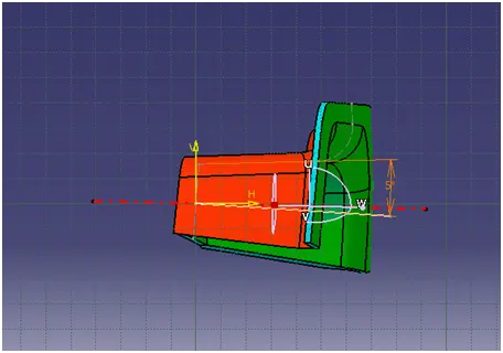
Then the surface having good draft angle
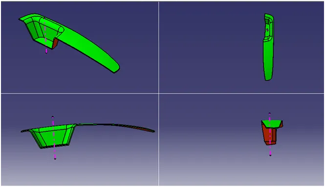
Isometric, Front, Top & Side view
Closed Surface.