Week 9 - Challenge 2 - Switch Bezel Design
DRAFT ANALYSIS:
To ensure the moulded product to eject from the core without damage on the sliding walls, darft is used.
Draft is defined as taper angle or draft angle of certain degree given to the core and cavity. If consider the walls of core & cavity be in straight or perpendicular, then during ejection the mould product walls will get damage due to friction created on the core walls. So in order to prevent this we use draft angle.
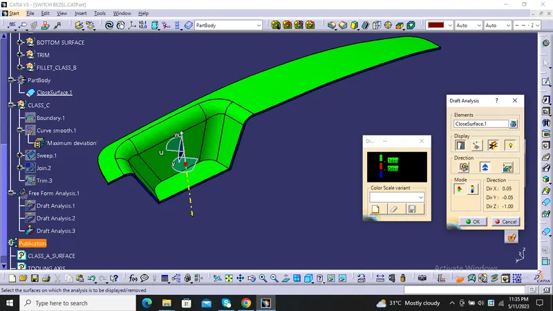
We also need to ensure that our given draftangle , makes the product manufacturable. So for that purpose we came up with draft analysis. In draft analysis we check the designed product clears the analysis with our input angle.
Draft angle - the nominal draft angle should be greater than 3 deg, whereas in some case on designing ribs and screw holes we can't give that much so we can go on with 0.5 deg to 1 deg by following the design standards.
TOOLING AXIS:
Tooling axis is the directional axis of tool and die acting axis, whether in injection moulding the core and cavity acting direction is refered to the tooling direction or tooling axis. Draft analysis can be done with reference to the tooling axis only. so it is must to create the right tooling axis.
To create tooling axis in CAD there are many ways, we follow bisecting line ,method for this switch bezel design. the pocket of the bezel has three sides so we cant go with simple creation.
Steps:
Make a point on the bottom surface at zero. with that as positioned sketch created on yz plane, now intersect along yz plane and with two inclined wall lines using bisect creat a line at the point at centre consider to be yz plane axis.
And now with the same point create xz plane and intersect the surface along xz direction , create a line at the cetre point , and give an angle of 7 deg to the intersected wall of the surface, and consider it to be xz plane axis
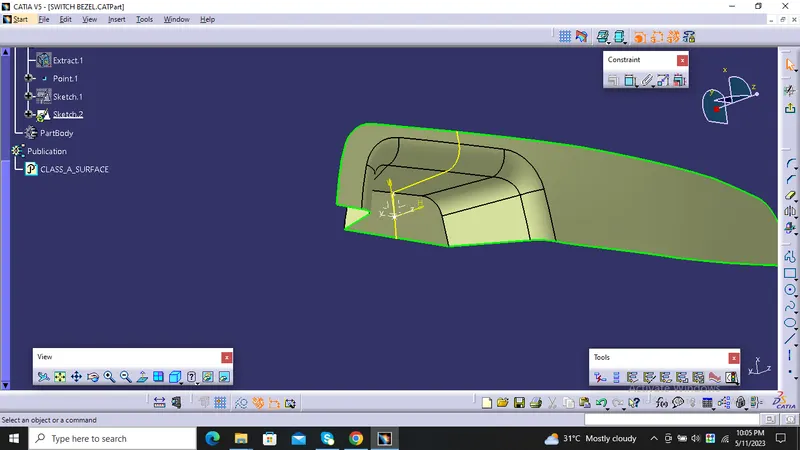
Now bisecting these two yz and xz plane sketch lines we get the tooling axis.
DRAFT ANALYSIS :
Ensure the given class A surface has no flaws in it, and then perform draft analysis in class A surface.
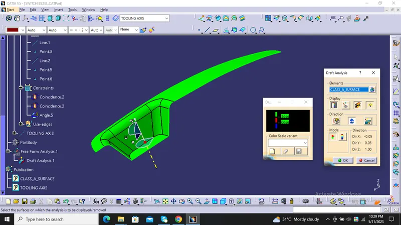
Then go on creating the class B surface following design standards, after that create class C surface and trim and fillet the surfaces, to obtain the reqiured closed surface , perform draft analysis with created closed surface.
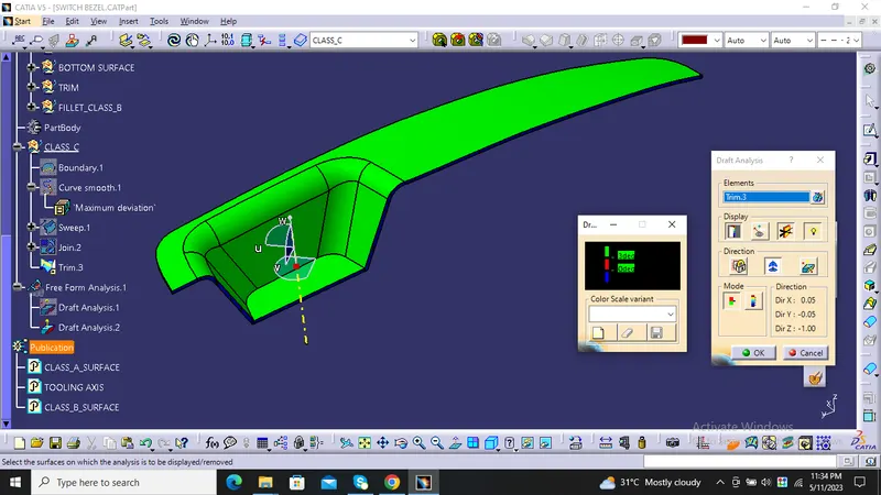
The thickness of the component was given 2.5mm and then use close surface command to get the final output part body/ solid model. and perform draft analysis.
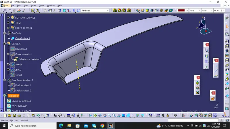
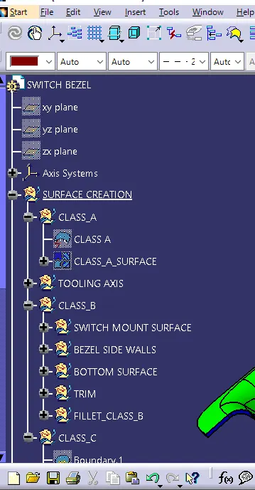
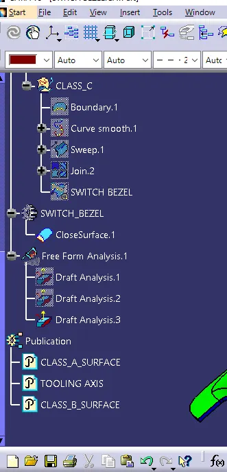
TREE STRUCTURE:
ORIENTATION VIEWS:
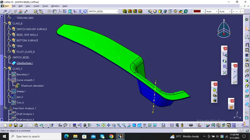
ISOMETRIC VIEW:
FRONT VIEW:
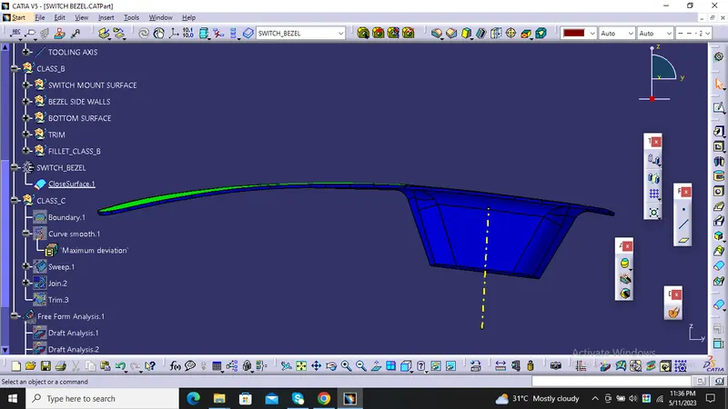
SIDE VIEW:
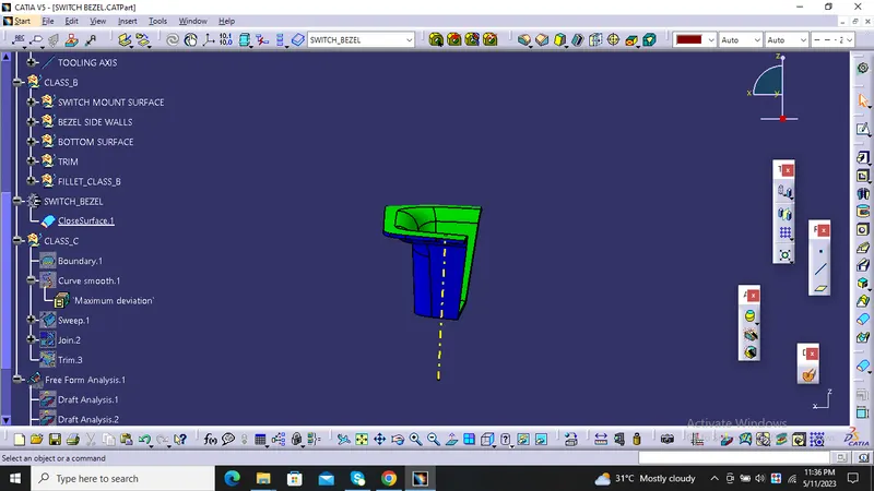
TOP VIEW:
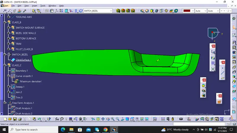
Thus the part body /solid model of the switch bezel is created from the given class A surface and performed draft analysis .