Week 9 - Challenge 2 - Switch Bezel Design
AIM :
Create the Switch Bezel Plastic component through the given Class-A surface. To begin with, the tooling axis for the given Class-A Surface should be created meeting the requirements of the draft angle and at the end perform the Draft analysis on the model.
Switch bezel :
Is a car part which contains switches and buttons to control different functions like window control,door lock,media etc. It is located at the inner portion of the door. The procedure used to create the part was same as the base bracket one. Class A surface was used to create the tooling axis. Class B surface was created at a distance equal to the thickness which was the identical surface of class A. Class C was formed as the wall of the model and then all the three surfaces were joined together and draft analysis was carried out.
GIVEN INPUT A SURFACE :
Input are provided by styling team. With the help of the Surface A we will make the surface B and surface C as well. After that we will do the tickining using close surface tool. Atlast we will do the draft Analysis. With the Analysis we will understand the behaviour of the entitre model.
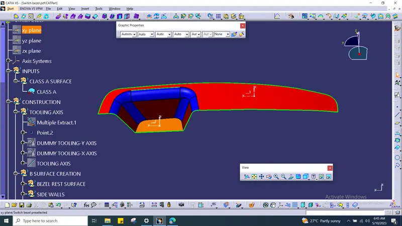
EXPLANATION OF CREATING TOOLING AXIS :
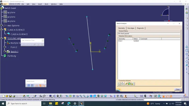
With the help of surface A, we will exact the some surface and create zero co ordinate point ,Axis system. Then we need to drawing construction line after with the help of construction line we need to create bisecting line. For better inderstanding refer below image.
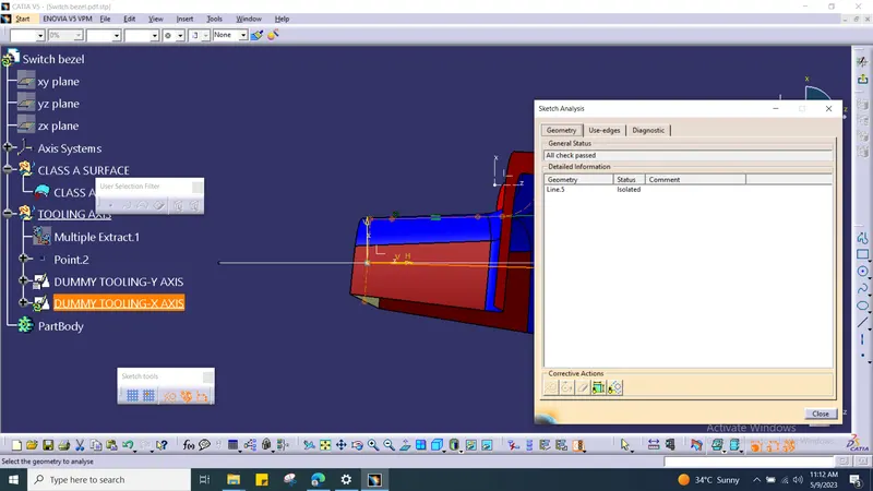
And again need to create the same step in different XZ axis. Here we have one side wall only. So that we given the dims of 3 degree.
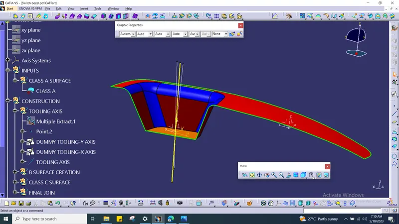
TOOLING AXIS :
With the help of two dummy tooling axis we need to create the tooling axis.
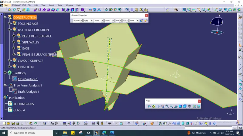
CREATION OF B SURFACE :
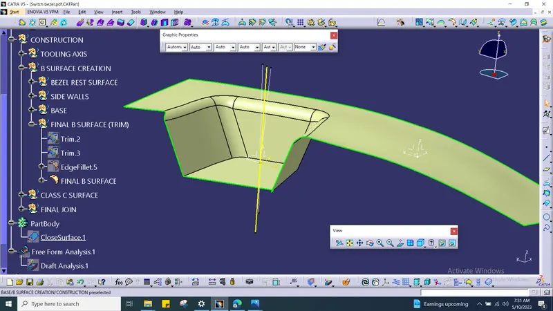
FINAL TRIM OF B SURFACE:
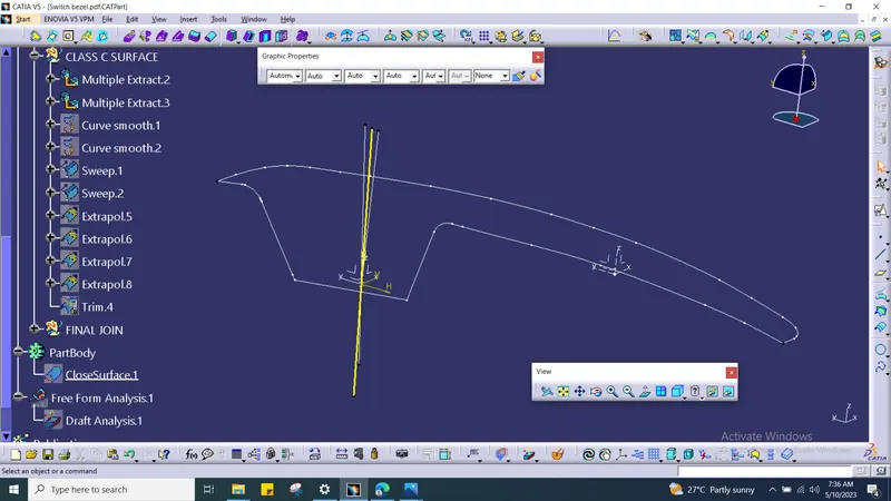
CREATION OF C SURFACE :
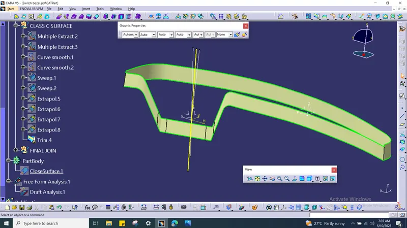
Inorder to create C surface we need to create boundary using multiple exact tool.
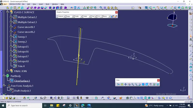
For better profile we need to do have smooth surface due to that we will get the more better profile.
JOINING:
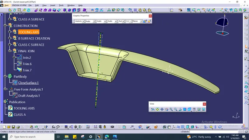
For surface A and C we need to join first and then we need to trim it off.
CLOSE SURFACE :
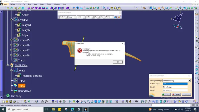
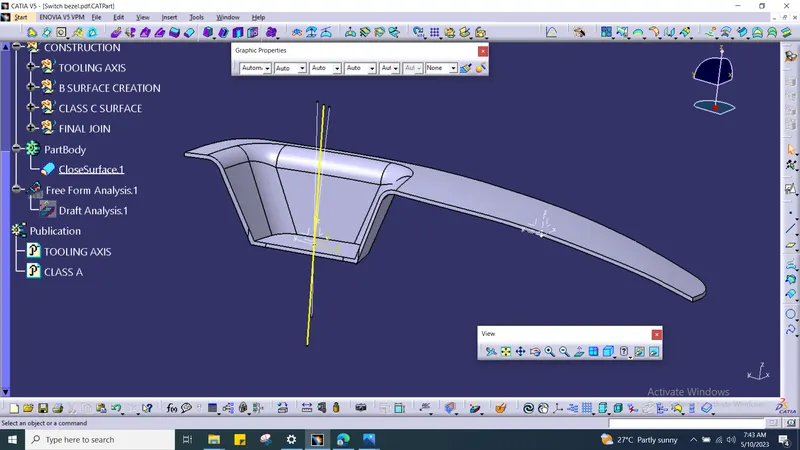
Finally we need to thick before that we need to check the boundary condition. Then we need to do thicken using close surface tool.
DRAFT ANALYSIS :
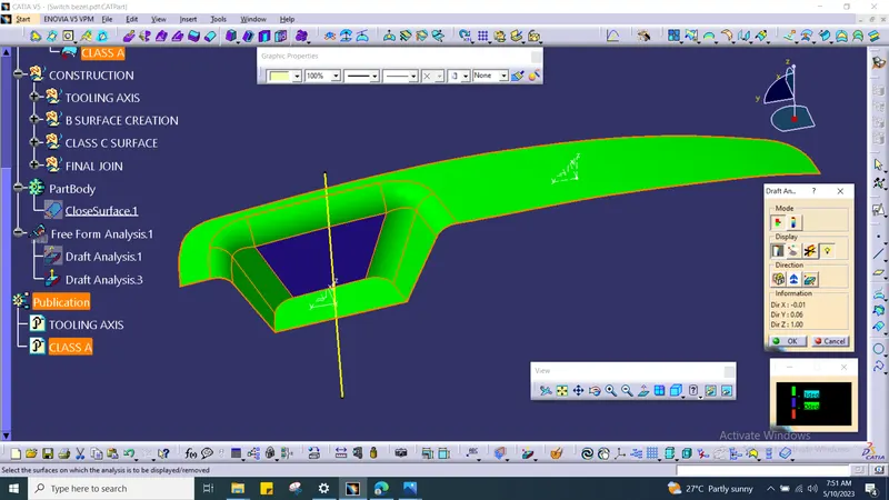
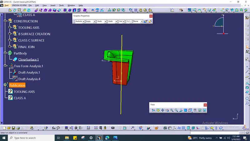
3 Degree, Draft Angle.
CLASS A SURFACE:
FINALL SURFACE :
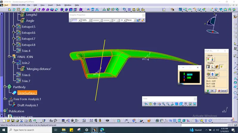
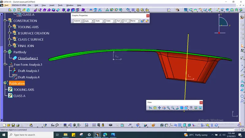
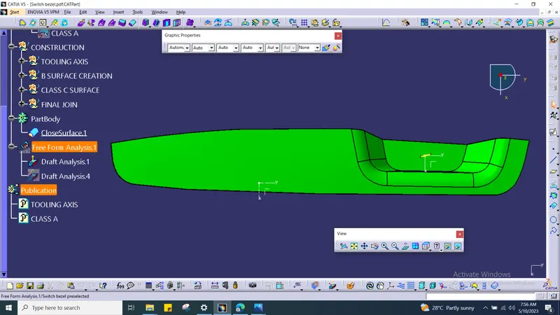
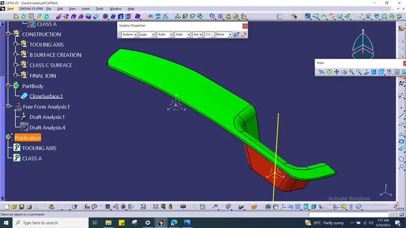
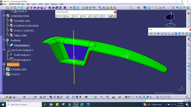
Green colour : positive ( Safer condition )
Blue colour : Average ( Acceptable )
Red colour : Negative ( Bad condition )
With the help of colour code we can identify the profile condition.
FRONT VIEW :
TOP VIEW :
SIDE VIEW :
ISOMETERIC VIEW :
CONCLUSION :
As per above instrction given we created the surface B, C and draft analysis using close surface method.