Week 9 - Challenge 2 - Switch Bezel Design
Week 9 - Challenge 2 - Switch Bezel Design
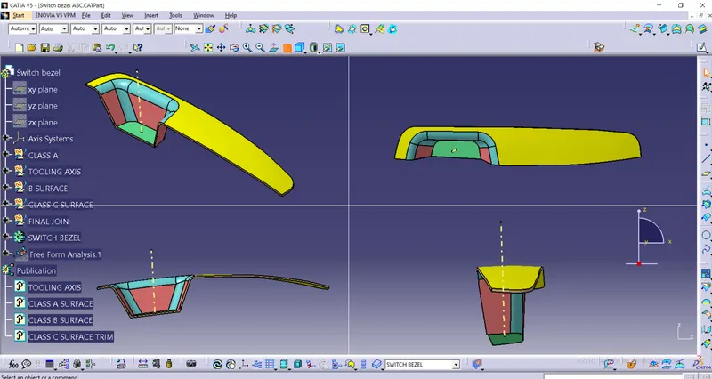
A switch bezel plastic component is created using class-A surface as shown below. The component is made 2.5 mm thick with the help of offset and close command.
The steps used for making the component can be seen in the Tree structure which has different geometrical sets arranged in sequence. As the class A surface is already given, the next step is to define Tooling axis.
Tooling axis
The Tooling Direction is basically the direction that the mold pulls apart. The mold is built in two separate pieces, basically. You have a Cavity side and you have the Core side. The Core pulls apart from the Cavity and that's the Dyeline or the Tooling Direction. Again, depending upon where you're working at, you may have a different name for it. So, when you go in and you create that Tooling Direction, you want to make sure that whatever you create is going to be used as a reference to design your data up against. So, when you add in your ribs, maybe some pockets, walls, whatever that may be, bosses, the walls are going to be drafted based off of the Tooling Direction. It's to make sure that the Core can pull apart from the Cavity, nice and clean.
Creating Tooling axis by Bisecting method
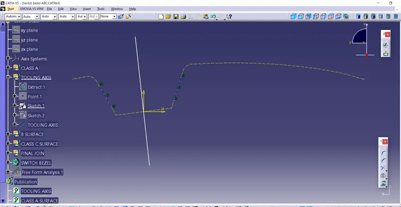
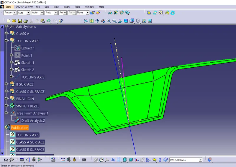
In this surface the tooling axis is created by considering the center point on the bottom face of the pocket. Then creating a sketch in Y Direction by taking YZ plane along the length of the surface and projecting the outer boundary. In the current view position the two lines are drawn on the draft projected lines. Then a Bisecting line is created with respect to the two drawn lines as represented by 'sketch 1' in the below picture.
After that considering X Direction and projecting the outer surface border on the XZ plane. Here we are having only one draft face line so drawing a line from the center at a random appropriate angle as shown below.
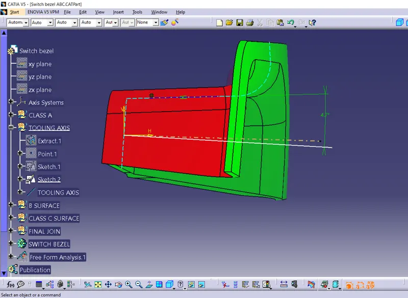
Now the tooling axis can be created by forming a Bisecting line using 'sketch 1' (blue line) and 'sketch 2' (purple line) lines which can be represented as below. So the Tooling axis line is represented in yellow color and dotted line. The Tooling axis is then Published using 'Publication' command.
Creating class-B surface
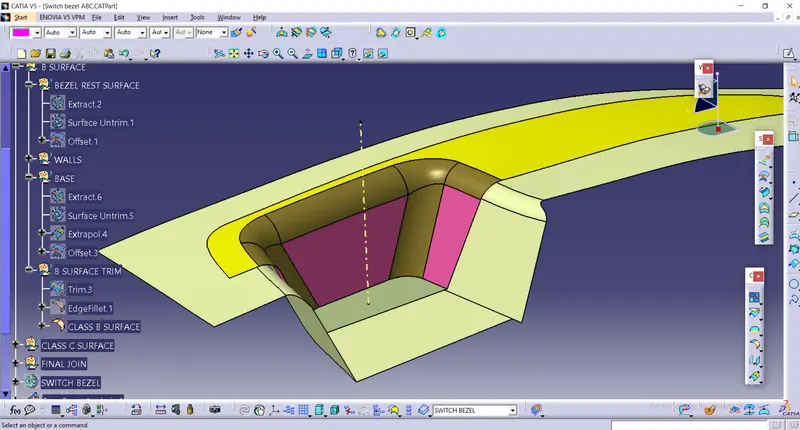
Now after creating the Tooling axis, class-B surface is created by Extracting the Side, Bottom, and Top faces, and then Untrimming and Extrapolating them. After that offseting them to 2.5 mm as shown below. The Geometrical sets of class B is also visible in the Tree structure shown below. The class-B surface is also published for the ease of not finding it.
Class-C surface
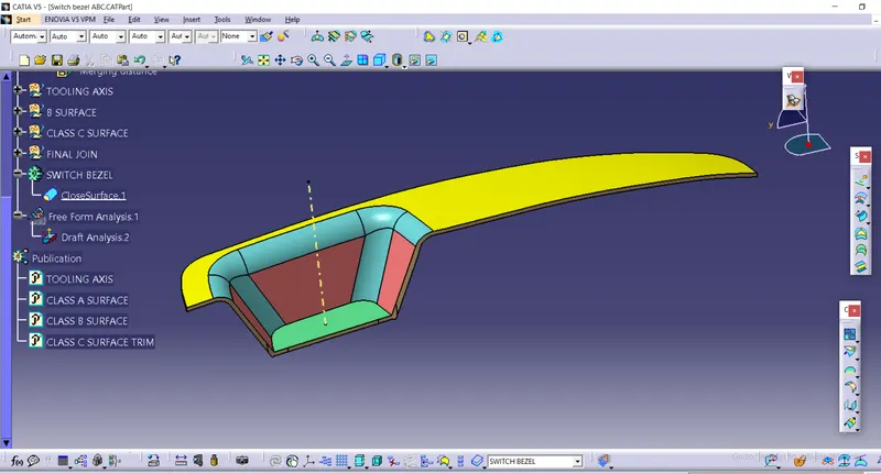
Class-C surface is the surface that closes the class-B surface. And it is created by Extracting the boundary lines of Class-A surface. The boundary is extracted in two parts which is represented in Blue and Cayn color as shown in below picture. Then 'Curve Smooth' command is used to smoothen the lines. After that lines are made to an extended drafted surface using the 'Sweep' command. This surface is represented in Green color in below picture. The class-C is also published using 'Publication' command.

Switch Bezel complete Surface
After creating class-B and class-C surfaces, the class-A and class-C surfaces are joined together with the help of join command. Then the Join surface and class-B surface is trimmed to get a complete hollow Switch Bezel Surface.
Switch Bezel part with 2.5 mm thick
Now as we have the complete closed surface with 2.5 mm thick, it can be converted to a solid part having a thickness of 2.5 mm by using 'Close Surface' command. The below picture represents a solid Switch Bezel Plastic component of 2.5 mm thickness.
Draft Analysis
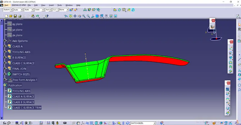
For the proper and safe removal and lifting of the component it is necessary to have sufficient draft allowances on each faces. So the drafted faces and its drafted angles can be checked using 'Feature Draft Analysis' command. To use the draft analysis it is necessary to select the view mode to 'Material' by clicking on the 'Question mark' sign in the 'Shading views mode'.
Now as the draft analysis is activated, first we need to set the compass on the tooling axis direction and put the 'Red cross mark' on the component and click on it, which results in selection od the part and it becomes in green and red color. Now select the first button in the display section which displaays the dialog box representing the different draft ranges with particular color as shown in below picture. This draft range dialog box is having 3 colored vertical lines namely Green, Sky blue, and Red. The Red color represents that the component having red faces are having negative or less than zero draft. The Sky Blue color represents the draft range from 0 to 2.85 degree. And the Green color line represents draft angle above 2.85 degrees.
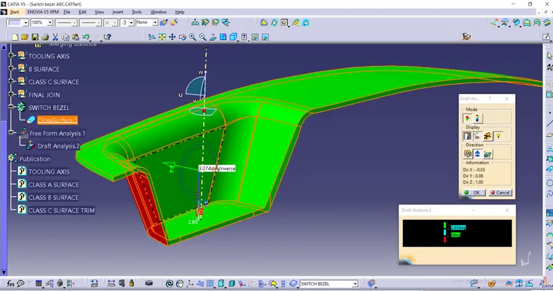
Thus the above details represents the creation of closed solid Switch Bezel Plastic component having 2.5 mm thickness.
Different views
The image below represents different views of the part. The top left section reepresents Isometric view of the part. The top right section represents Top view of the part. Then bottom left section represents Front view of the part. And the bottom right section represents Side view of the part. The image also represents complete Tree Structure having different geometrical sets, Close body, Draft analysis, and different publications.