Project - Speed Control of a Direct Current (DC) motor
Simulink Project - Speed Control of a Direct Control (DC) Motor
To design a DC motor let us consider certain parameters;
j = 0.01; % Moment of Inertia of rotor
b = 0.1; % friction
Km = 0.01; % back emf
Kt = 0.01; % torque
Ra = 1; % Armature resistance
La = 0.5; % Armature inductance
To find poles consider;
fn = 1; % natural ferquency
wn = 2*pi*fn; % in rad/s
z = 0.5; % for under-damped condition
p1 = -z*wn + wn*sqrt(z^2-1);
p2 = -z*wn - wn*sqrt(z^2-1);
therefore P = [p1;p2]
P =
-3.1416 + 5.4414i
-3.1416 - 5.4414i
Now for PID controller design we require A and B matrices, which can be obtained as;
A = [-b/j Kt/j ; -Km/La -Ra/La];
B = [0 ; 1/La];
% the values of gain k1 and k2 can be found by using PLACE command
containing A,B,P matric values
K = place(A,B,P)
So
K = 38.3133 -2.8584
where K1 or Kp = 38.3133 and K2 or Kd = - 2.8584
Now the equations for simulink model can be obatined applying Kirchhoffs closed loop law in the given schematic.
L(di/dt) + RI = V-Kb(d0/dt)
and as per Newtons law
J(d^20/dt^2) + B (d0/dt) = Kt*I
converting above equations to 's' domain
LsI(s) + RI(s) = V(s) - Kbs0(s)
therefore I(s) = [V(s) - Kbs0(s)] / Ls+R ------------(1)
Js^20(s) + Bs0(s) = Kt*I(s)
w(s) = s0(s) = [Kt*I(s)] / Js+B -------------(2)
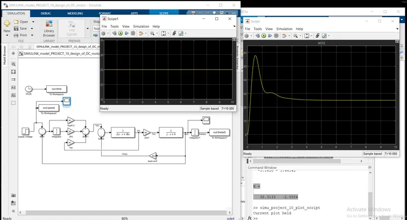
considering the above equations 1 and 2 we can build simulink model as shown in below picture.
In the model, various value of Kt is applied to varify and get desired results.