Week 9-Challenge
Aim
To mesh the given component with a target size of 5mm and create connectors and attach the various parts of the model according to the conditions given below.
1. Right_Rail_2 & Front_truss_1:- Seam-Quad(angled+capped+L)
2. Left_Rail_2 & Front_truss_1:- Quad elements
3. Front_truss_2, Front_truss_1 & Right_Rail_1:- Spot weld with 3 Layers and 5 mm Diameter
4. Front_truss_2, Front_truss_1 & Left_Rail_1:- Hexa (Adhesive)
5. Rear_truss_2 & Right_Rail_2:- Bolt Connector
6. Rear_truss_2 & Left_Rail_2:- Bolt Connector
7. Right_Rail_1 & Right_Rail_2:- Spot-weld with Rigid Elements
8. Left_Rail_1 & Left_Rail_2:- Spot-weld with Spring Elements
9. Rest all the component left Join them with suitable connectors
Methodology
- Import the geometry into HyperMesh and check for geometric errors.
- Mesh the components with a target size of 5mm
- Connect the different components using suitable connectors
Procedure
All the components were meshed with a target size of 5mm
Right_Rail_2 & Front_truss_1
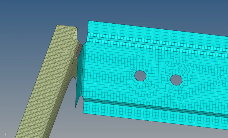
These components were connected with seam-quad(angled+capped+L) from 3D > connectors > seam > type was selected as seam-quad(angled+capped+L) > spacing was set as 5mm > respective components were given as input for comps > tolerance was set at 10mm > create.
The connector is shown below.
Left_Rail_2 & Front_truss_1
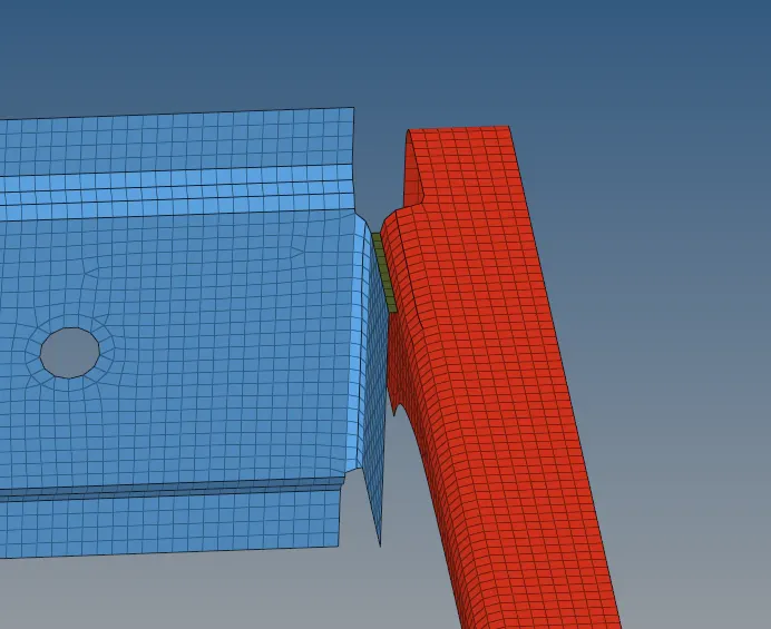
Similarly quads were created from the same set of options using 3D > connectors > seam > type was selected as quads > spacing was set as 5mm > respective components were given as input for comps > tolerance was set at 10mm > create.
The connectors are shown below.
Front_truss_2, Front_truss_1 & Right_Rail_1
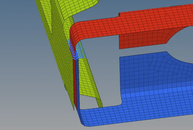
The connectors were created using 3D > connectors > spot > nodes were selected > comps were selected > num layers were set as 3 > tolerance was increased to 50 since three components were involved > diameter was set to 5mm > type was set as weld > create.
The connectors are shown below.
Front_truss_2, Front_truss_1 & Left_Rail_1
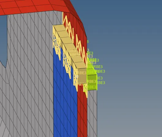
The connectors were created using 3D > connectors > area > elems and comps were selected > type was set as hexa > create.
The connector is shown below.
 \
\
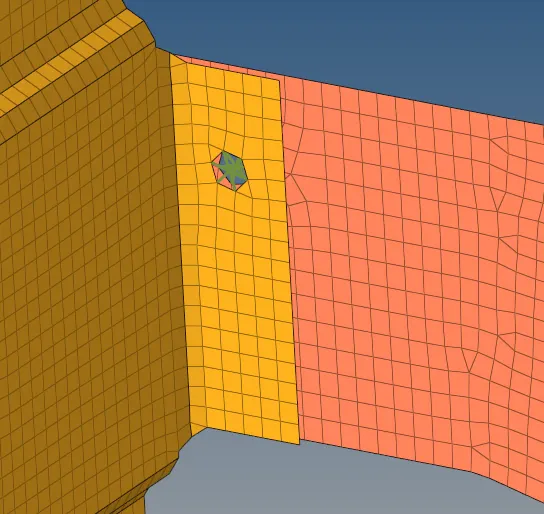
Rear_truss_2 & Right_Rail_2
The connector is created from 3D > connectors > bolt > the nodes were selected > comps were selected > tolerance was set as 10 mm > type was set as bolt (general) > consider existing hole only option was changed to create hole, if none > create.
Given below is the connector.
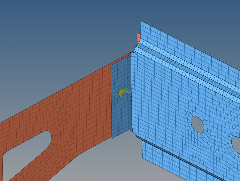
Rear_truss_2 & Left_Rail_2
Similar to the previous bolt it was created from 3D > connectors > bolt > the nodes were selected > comps were selected > tolerance was set as 10 mm > type was set as bolt (general) > consider existing hole only option was changed to create hole, if none > create.
Given below is the connector.
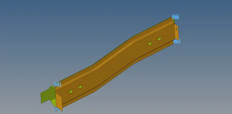
Right_Rail_1 & Right_Rail_2
The connectors were created using 3D > connectors > spot > nodes were selected > comps were selected > num layers were set as 2 > tolerance was set as 10 mm > diameter was set to 5mm > type was set as rigid > create.
The connectors are shown below.
Left_Rail_1 & Left_Rail_2
The connectors were created using 3D > connectors > spot > nodes were selected > comps were selected > num layers were set as 2 > tolerance was set as 10 mm > diameter was set to 5mm > type was set as spring > create.
The connectors are shown below.
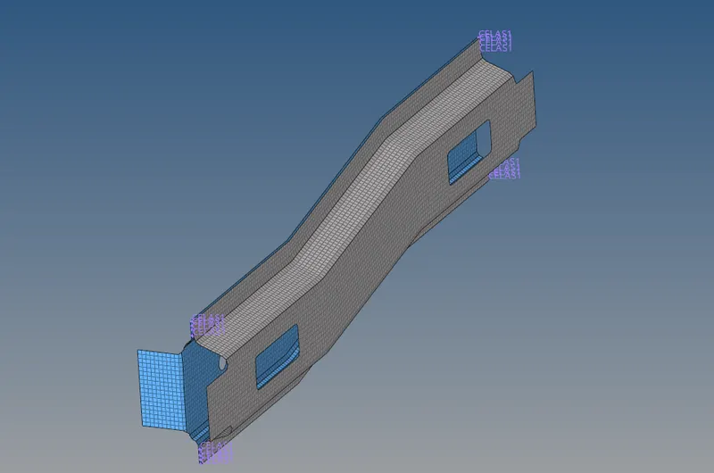
Rest of the components such as reinf plate and rear truss 1 was connected to other parts using seam welds.
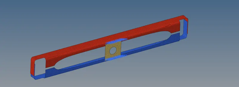
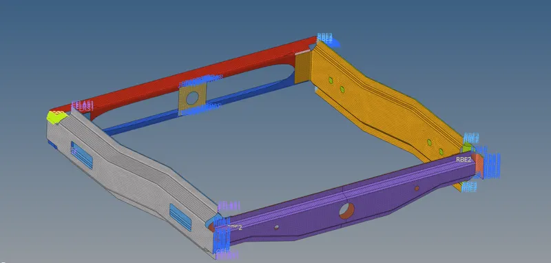
The whole model after creating connectors are shown below.
Conclusions
- The components were meshed with the target size of 5mm
- Connectors according to the given list were used to connect the components
- Remaining free parts were connected using appropriate connectors.
- Property and material was assigned to the components