Week 8-Challenge
Aim
To create tetramesh for cover and hub, crank housing and suspension assemblies according to the given quality criteria.
For cover and hub, the target size, minimum size and maximum size of the element is 5mm, 2mm and 7mm respectively.
For crank housing and suspension assembly, target size is 6mm. Tet collapse is set at 0.15 for both models.
Methodology
- Import the geomety into HyperMesh.
- Cleanup the geometry
- Deploy mesh according to the given quality criteria
- Remove free edges and T-junctions if they were created in the 2D tria mesh.
- Check if elements have failed for tet collaspe and rectify them.
Procedure
Cover and hub
The cover and hub were imported into Hypermesh and the model was checked for free edges and other geometric issues.
Both cover and hub were meshed using Quick Tetramesh from View > Browsers > HyperMesh > Utility > Quick Tetramesh.
The model was checked for tet collapse in Tools > check elems > 3D > tet collapse and it was found that no elements were failing.
Given below is the 3D tetramesh of hub.
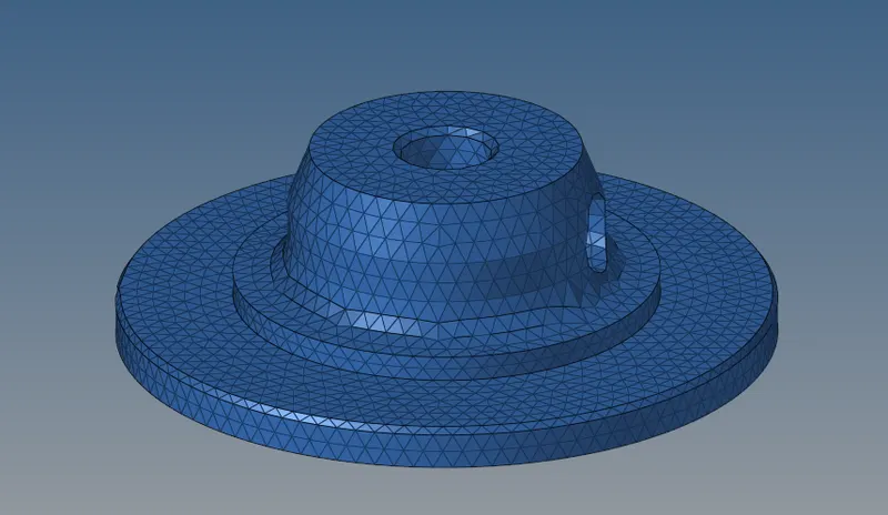
Given below is the tetramesh of cover.

Given below is the assembly.
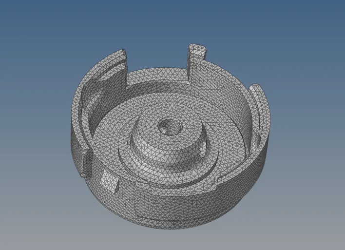
Crank housing
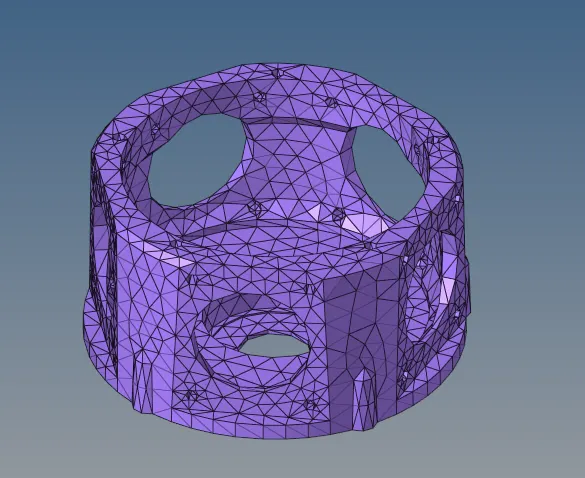
The crank housing was imported into Hypermesh and the model was checked for free edges and other geometric issues.
The component was 2D meshed with trias using 2D > automesh. This 2D mesh was converted into tetramesh using 3D > tetramesh > Tetra mesh > set elems in Fixed trias/quads to tetra mesh > mesh.
The mesh was checked for tet collapse and 43 elements were failing. The failing elements were fixed using 3D > tetramesh > Tetra mesh > fix 3D elements > Tetra collapse was set to 0.15 > fix.
When the mesh was checked again for tet collapse, no elements were failing.
Suspension assembly
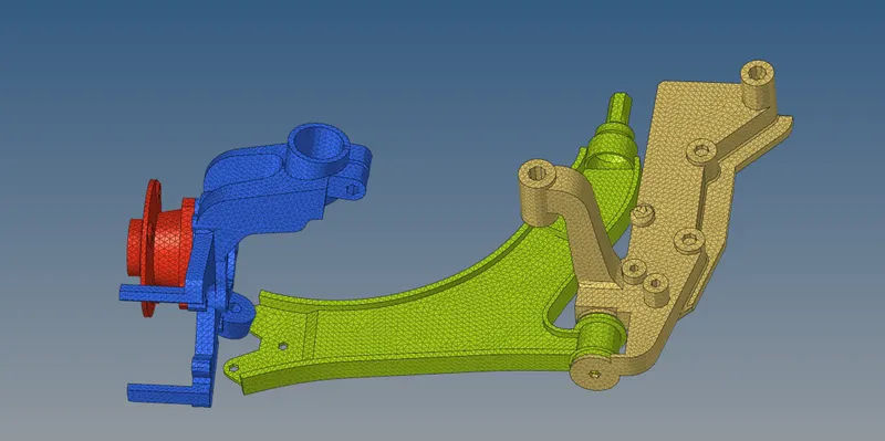
The suspension assembly was meshed with trias first with a target size of 6mm. While tetrameshing this component, 3D mesh could not be deployed because of a T junction in the feature given below.
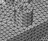
Therefore, a finer mesh was deployed in this region to avoid the T-junction and tetramesh was created using 3D > tetramesh.
The elements failing for tet collapse was fixed using 3D > tetramesh > fix 3D elements. No elements were failing when it was checked for failure criteria.
The meshed assembly is shown below.
Conclusion
- Tetramesh was deployed for all models without any failure for tet collapse
- Appropriate properties and materials were assigned to each model
- Quick tetramesh option gives the best mesh with least number of failed elements followed by Tetra mesh and volume tetra.