Simulating side crash of Dodge Neon BIW using Radioss
Objective
To simulate side crash of Dodge neon BIW according to the given parameters and analyse the results.
Input parameters
- Check unit system and either follow [Mg mm s] or [Kg mm ms].
- Create appropriate interface ,friction 0.2 and recommended parameters.
- Make sure of no penetration and intersections.
- Create rigid wall with friction 0.1 as per referance model.
- Compare the model weight with the referance model and use added masses to reach target weight 700kg while getting CG about the required range.
- Initial velocity as shown in picture.
- Use model checker to ensure good quality.
- Timestep :0.5 to 0.1 microseconds.
- Run 80ms.
Output requests
- Sectional force in the cross member.
- Intrusion at B pillar,hinge pillar and fuel tank region.Provide recommendation on what can help to reduce Fuel tank intrusion.
- Peak velocity of inner node of the door
Procedure
Model was imported into Hypermesh and the unit system was found to follow [kg mm ms].
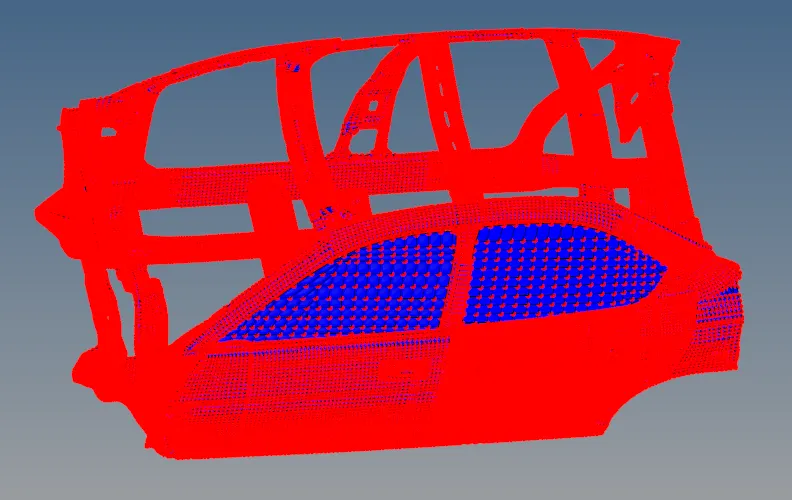
The existing interface was deleted and a new type 7 interface with all nodes and surfaces were created with friction 0.2 and recommended parameters.
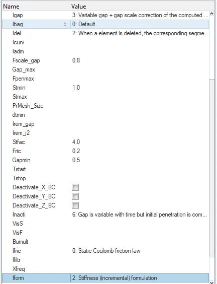
Given below are the recommended parameters given as input.
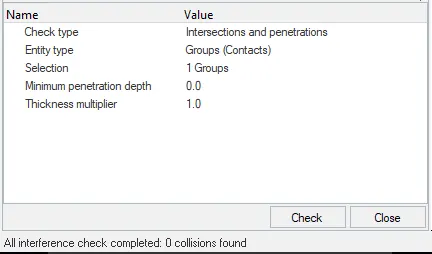
Model was checked for intersections and penetrations and none were found.
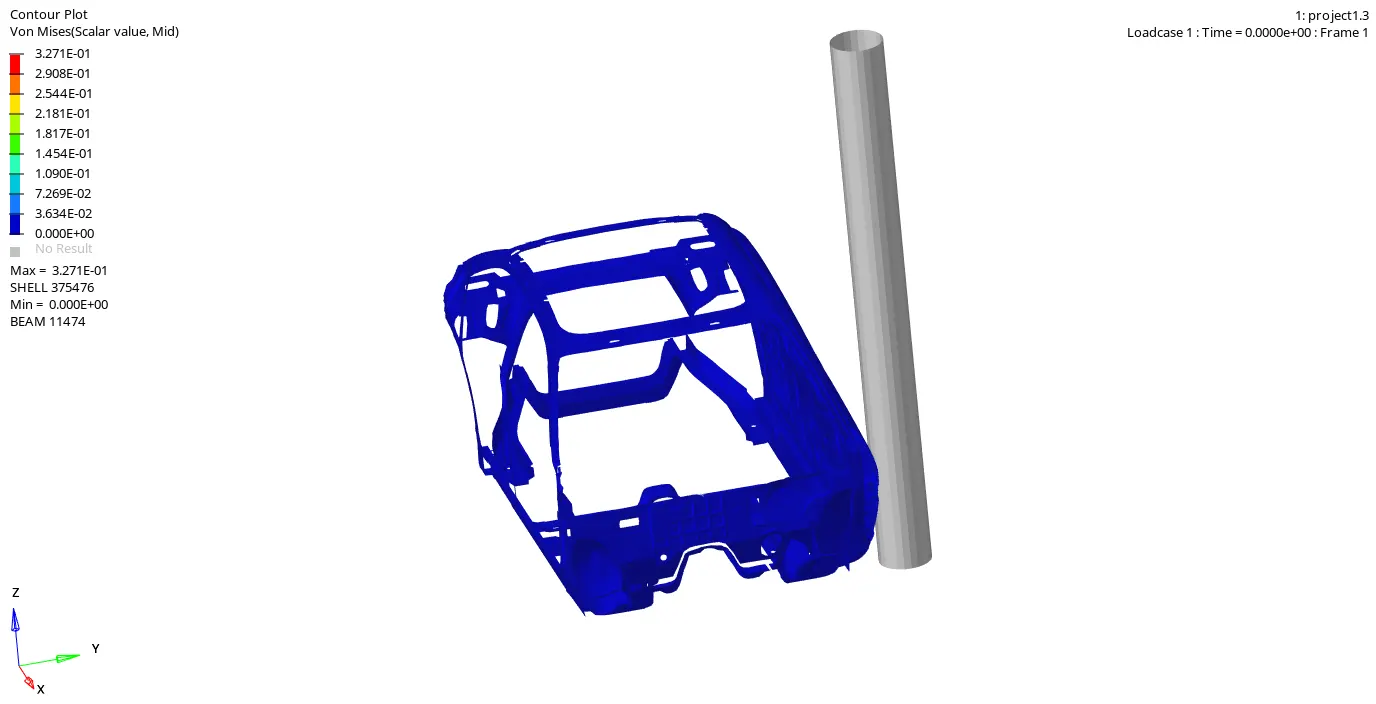
Side pole was created according to fmvss 214 standard with pole diameter as 254mm. Friction was given as 0.1.
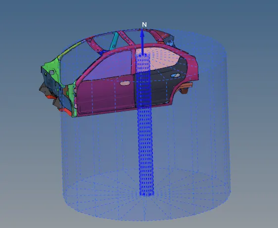
17 mph (7.599 mm/ms) was given as initial velocity input according to fmvss 214 standard.
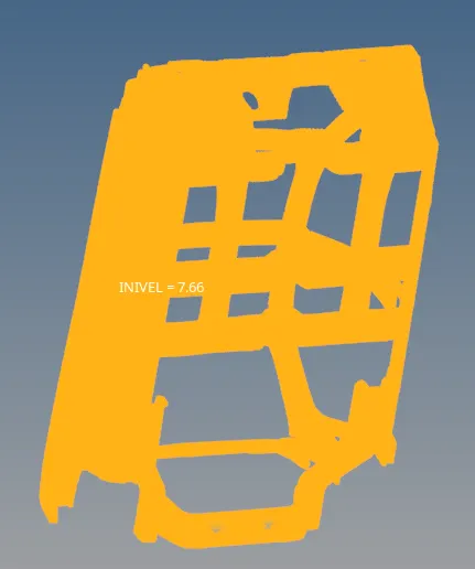
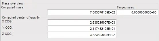
The model was then imported into hypercrash and masses were added to reach target weight 700kg while getting CG about the required range.
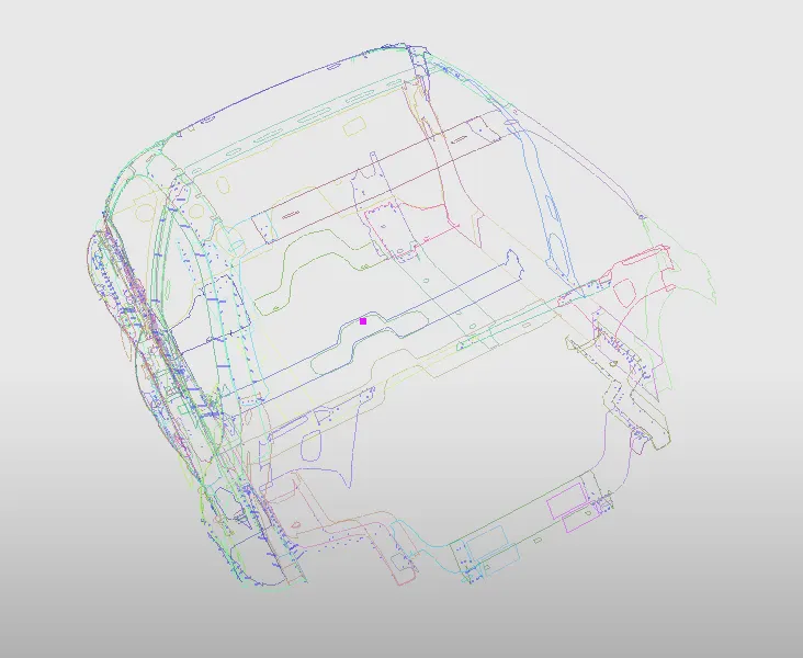
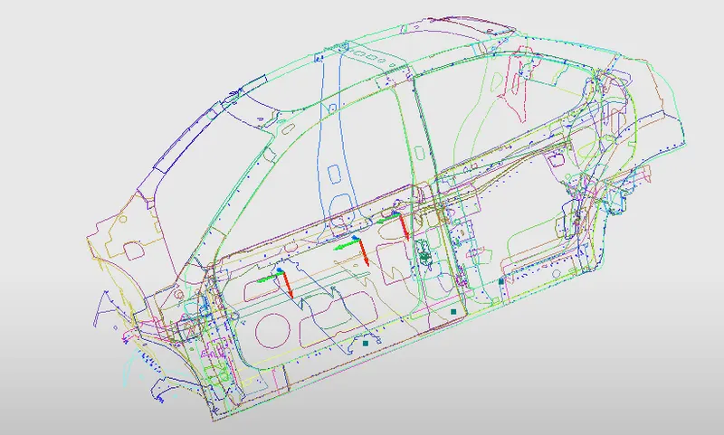
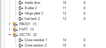
Two moving frames were created in two members using Create New > System > Frame and using the same three nodes for defining the moving frame, two sections were created using Create New > section > default sections. grshel_ID was defined accordingly. The two sections are given below.
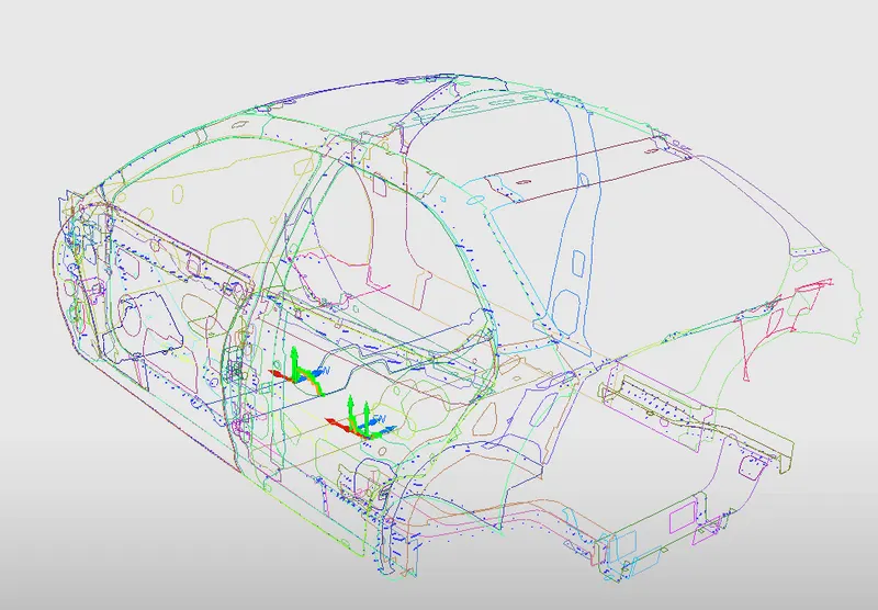
The section cards for the above mentioned sections are shown below.

To measure intrusions at hinge pillar, B pillar and fuel tank region, TH/NODE were created for three nodes in these parts respectively using Create New > Data history > TH of nodes. Accordingly, three fixed skews were created opposite to these nodes using Iskew option in node time history card. To measure sectional forces at cross members, time history cards for two sections were also created.
From Quality > Model checker > Run , model checker was run and no errors were found.
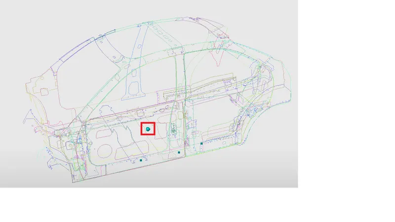
TH/NODE was created for a node on the inside part of the door to measure its peak velocity.
The time history cards for all the above mentioned nodes are shown below.
Minimum time step was set as .05 microseconds and runtime was set as 80 milliseconds.
Results
The simulation gif is added below.
Given below are the node intrusions near fuel tank region, hinge pillar and B pillar. Blue, red and green represent intrusions at fuel tank, hinge pillar and B pillar respectively.
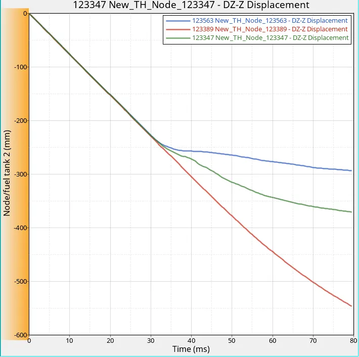
Upto 32 milliseconds the intrusions are equal for all the nodes with constant slopes because they are moving with the same initial velocity value. From 32 milliseconds the B pillar rocker arm will start to deform from the crash and at this point the intrusions become different for the nodes.
We can observe that displacements of each nodes follow a different slope after 32 milliseconds. This is because the crash slows down certain nodes and hence velocities are diffferent for each nodes.
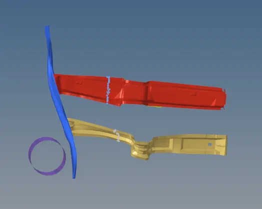
By looking at the deformation of the B pillar rocker arm we can explain the node intrusions. Node near the hinge pillar has the highest displacement because the area around that node has deformed the most compared to other nodes. Displacement for node near the B pillar is the second highest because the deformation is second highest around that region. The node near the fuel tank region has the lowest displacement because the deformation is the lowest there.
Node at fuel tank (blue plot) slows down the most because the fuel tank region is closest to the side pole while the car is impacting. Depending on the distance from the side pole, the velocity of nodes changes.
The node intrusion in the fuel tank region can be prevented by reinforcing the material of the fuel tank.
Cross member 1 is located at the base of B pillar and cross member 2 is located at the base of hinge pillar.
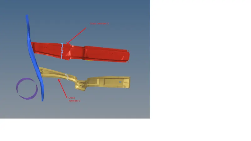
Given below are the plots of cross sectional forces along the normal.
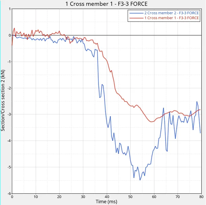
The forces for both cross members almost have a constant value until the crash starts and when the crash starts the forces are suddenly increasing.
From the plot given above we can observe that the peak normal force is higher for cross member 2. This is because around 50 ms the B pillar rocker arm is highly stressed around the hinge pillar and this force is transmitted to cross member 2. At this instant, the B pillar rocker arm is experiencing a relatively low stress around the base of B pillar and this force is transmitted to cross member 1.
Towards the end of the simulation, the rocker arm is experiencing similar value of forces around the base of hinge pillar and B pillar, therefore the forces propagated through the cross members have similar values.
The resultant velocity graph of a node on the inside part of door is shown below.
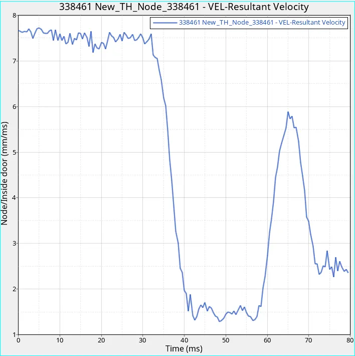
The peak velocity value of the node is 1.29 mm/ms.
Given below are the energy plots.
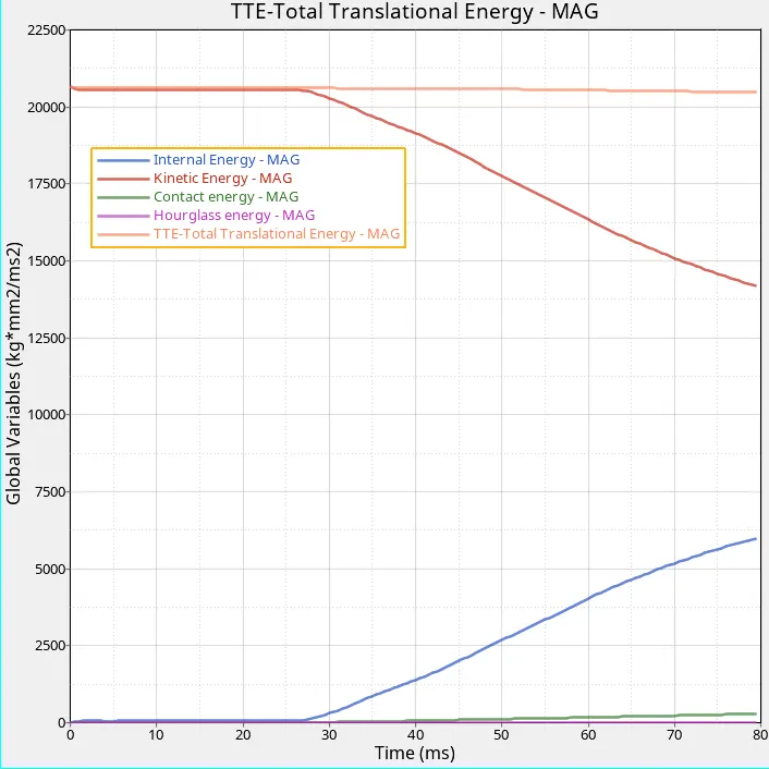
The sudden increase in internal energy starts with the impact. The kinetic energy starts decreasing from this point simultaneously. The contact energy starts increasing when the crash begins and it keeps on increasing continuously. The model has a significant value of kinetic energy even at the end of the simulation because it has not come to rest completely. We can say that numerical energies such as contact and hourglass energy are under control because the energy error value is only -1.6%.
Conclusion
The side crash was simulated according to the given parameters and the output requests were analysed.