Calculation of brake energy of US06 drive cycle using MATLAB
1. The MATLAB code for calculating brake energy of US06 drivecycle is given below:
clear all
close all
clc
f1=fopen('US06 drivecycle.txt','r');
mass=1770; %mass of the vehicle in kilograms
for i=1:2 %skipping comments
    comments=fgetl(f1);
end
for i=1:601 %storing time and velocity values into arrays from the text file
    B{1,i}=fgetl(f1);
    f=strsplit(B{1,i});
    time(i)=str2double(f{1,1});
    vel(i)=str2double(f{1,2});
end
brkenergy=0;
j=0;
BE=0;
for i=1:600 % calculation of brake energy
    if (vel(i+1))<(vel(i))
        j=j+1;
        a(j)=vel(i);
        a(j+1)=vel(i+1);
        BE=(1/2)*(mass)*(((a(length(a)))^2)-((a(1))^2));
    else
        a=[];
        j=0;
        brkenergy=brkenergy+(BE);
        BE=0;
        continue
    end
end
brkenergy=(brkenergy+BE)/1000 % converting brake energy from Joules to kiloJoules
 plot(time,vel)
 xlabel('time(s)')
 ylabel('Velocity(m/s)')
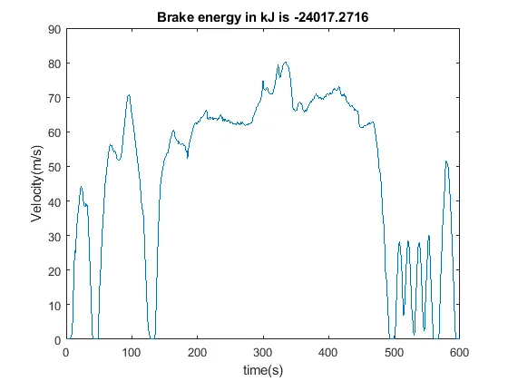
 title(['Brake energy in kJ is ' num2str(brkenergy)])
CODE EXPLANATION
The brake energy is found out by calculating change in kinetic energy when the vehicle starts to reduce its speed. The mass of the vehicle is set as 1770kg. Since energy is not path dependent, we can find out brake energy by finding out the difference in kinetic energies at the highest velocity value and the lowest velocity value when the vehicle starts decelerating. The sum of all these kinetic energies will give the total brake energy of the drivecycle.
The drivecycle used is US06 drivecycle. The link to the text file is attached below:
https://docs.google.com/document/d/1Zv1MLiipkgR_Tto7A52A9LqSc3ejQWu1wmJQVOjwuxQ/edit?usp=sharing
PLOTS
2. The braking torque of an EV motor is not as high as its accelerating torque due to the following reasons:
i) At high speeds, the motor is operated above base speed ( synchronous speed) and in the field weakening region. Above base speed, voltage is kept at rated value and frequency is increased which increases the speed but decreases the torque value.
ii) The peak battery charging rate is not as high as peak battery discharging rate. Therefore, regenerative braking torque cannot be as high as accelerating torque.
iii) The limitations associated with power converter is another reason. While recharging, the power converter may not have the same efficiency as discharging.
There are two major brake control strategies to coordinate regenerative and mechanical braking systems.
1.Series
2.Parallel
In the first strategy, only one type of brake is applied(either regenerative or mechanical) at a time.
However, in the second strategy, both of the brakes are applied at the same time. This strategy is more efficient as regenerative braking torque is low at high speeds, it can be coupled with mechanical brakes to bring down the speed. At low speeds, regenerative braking will be the dominant braking system.
3. Given below is the matlab code which plots contour of given motor speed, torque and efficiency values.
clear all
close all
clc
%asking for user inputs of speed, torque and efficiency values
k = input(['Enter the upper limit of motor speed in rad/s ']);
w=linspace(1,k);
j = input(['Enter the upper limit of motor torque in Nm ']);
t=linspace(1,j);
m = input(['Enter the number of efficiency values ']);
for i=1:m
     V(i) = input(['Enter the efficiency value no.' num2str(i),' ']);
end
[W,T] = meshgrid(w,t);
outputpower=T.*W;
% Kc, Ki and Kw are constant values used for the calculation of losses
Kc=0.9;
Ki=0.008;
Kw=0.00001;
%calculation of losses
Copper=Kc.*(T.^2);
Iron=Ki.*(W);
windage=Kw.*(W.^3);
Constant=20;
inputpower=(outputpower)+(Copper)+(Iron)+(windage)+(Constant);
efficiency=outputpower./inputpower;
contour(W,T,efficiency,V) %plotting the contour at given efficiency values
xlabel('Motor speed(rad/s)')
ylabel('Torque(N-m)')
CODE EXPLANATION
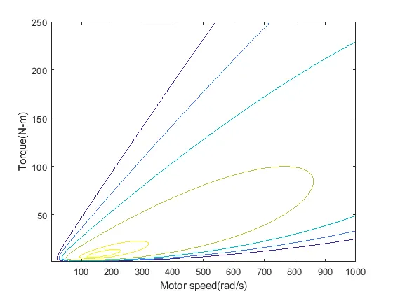
Inputs for motor speed upper limit, torque speed upper limits, number of efficiency values and the efficiency values are asked from the user. The input power is found out from the following equation:
Input power= output power+ losses
The losses are are found out from the following equations:
Copper loss= `Kc*(T^2)`
Iron loss=`Ki* w`
Windage loss=`Kw.(w^3)`
Kc, Ki and Kw are constant experimentally determined and in the code their values are 0.9, 0.008 and 0.0001 respectively. Another constant value of loss is added along with the above losses.
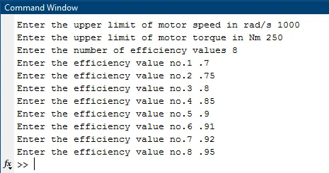
Given below is the inputs entered and the corresponding contour plot according to the inputs:
PLOTS