Week 9 - Challenge 1 - Base Bracket Design
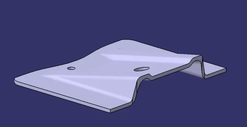
Aim: Create the Base Bracket plastic component through the given class-A surface. To begin with, the tooling axis for the given class-A surface should be created meeting the requirements of the draft angle and at the end perform the Draft analysis on the mode.
Class-A surface:
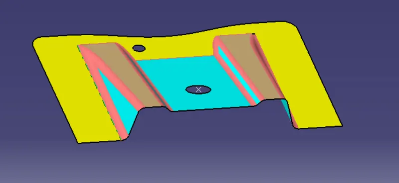
- Visible surface and aesthetic look.
- Surface provided by customer (OEM).
- Surface with textures.
- Don't have any features like rib, snap, bosses etc on class A surface.
Class-B surface:
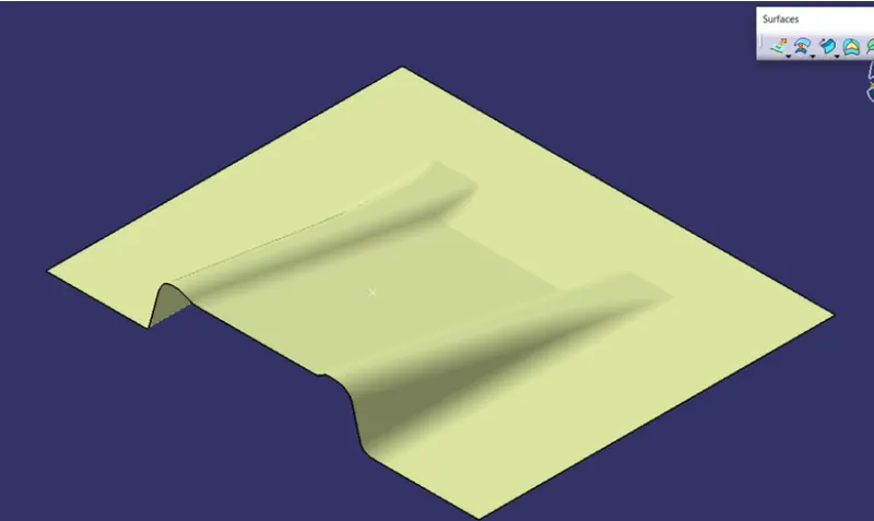
- Invisible surface.
- Surface mostly don't have textures.
- Surface need to be created according to class-A surface.
- Having all features bosses, snap, rib etc in B side surface only.
- Surface which is having tangent continuity is call class-B surface.
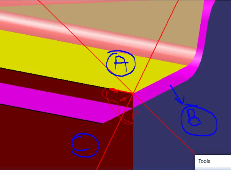
Class-C surface:
- join to Class-A and Class-B surfaces.
We have focused on the following things:
- Tooling axis
- Draft analysis
- Class-A surface
- Class-B surface
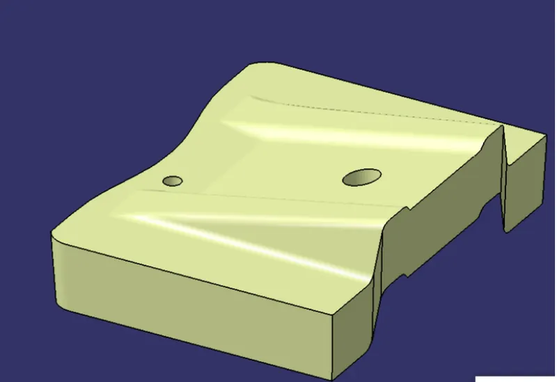
- Making a solid model from surface.
Following tools were used to reach the final step:
- Extract
- Un-trim
- Trim
- Extrapolate
- Offset
- Edge fillet
- Boundary
- Sweep
- Join
- Close surface
For Tooling Axis:
- First ensure the class-A surface is properly joined and has no discontinuity on it. For this we can use boundary command or join command.
- Analyze the model manually or visually to see which direction is most suitable for tooling axis.
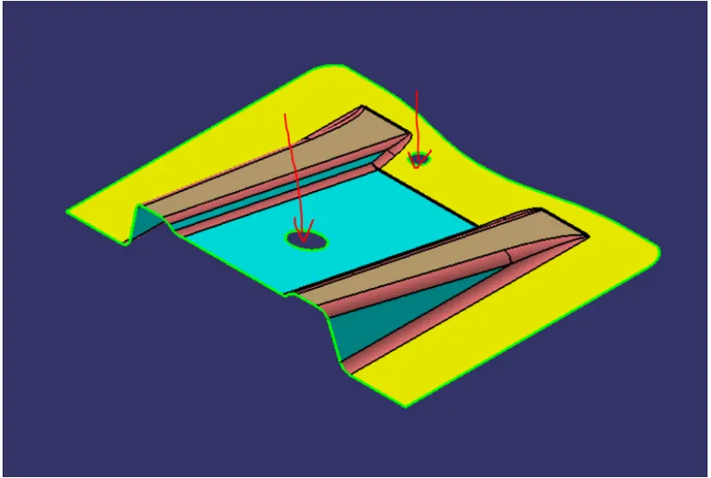
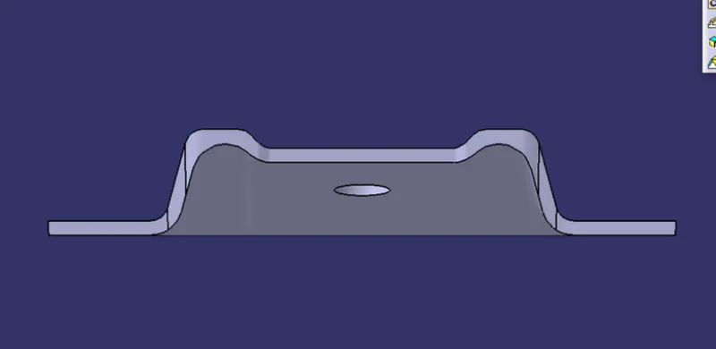
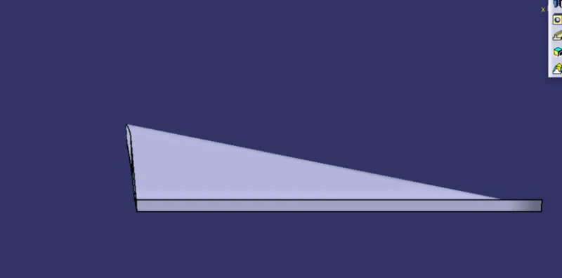
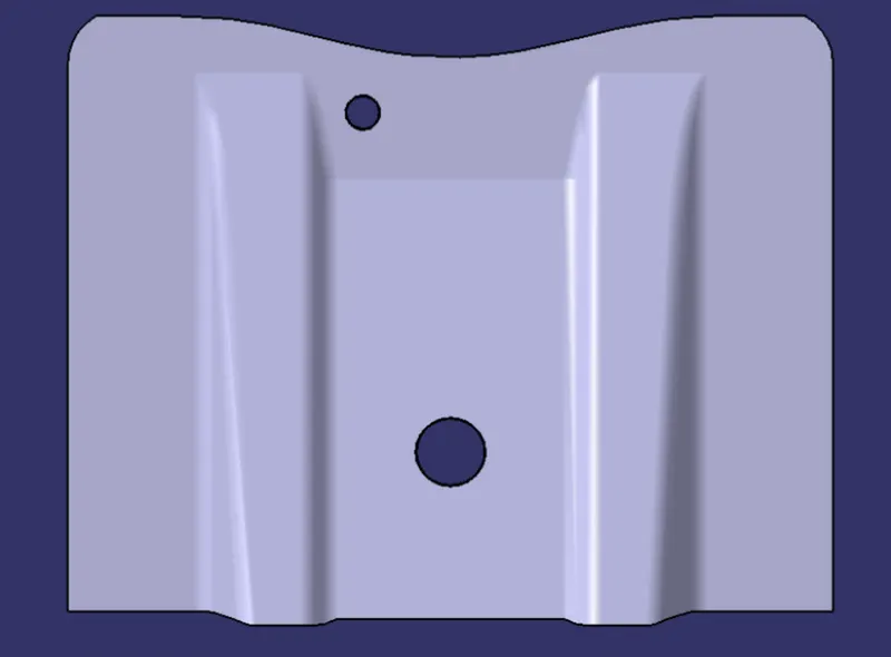
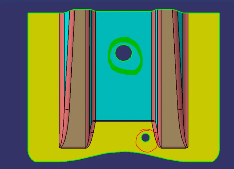
- As in 3D view, we can see 2 hole and a flat surface, we can directly take the tooling axis perpendicular to that. But to be sure, Let us a laze from all the view. the below image's the front side and top view shows the area that we have to keep in mide while choosing tooling axis. As from X we cannot see one hole so we cannot take axis along this. In Y we cannot see any hole so here to we cannot tooling aixs. But in Z we can see 2 hole and flat surface so we can taker tooling axis.
Bisecting line method:
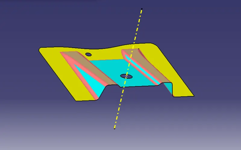
- Create an intersection of class-A surface with ZX plane and from the intersection create the tooling axis as shown below.
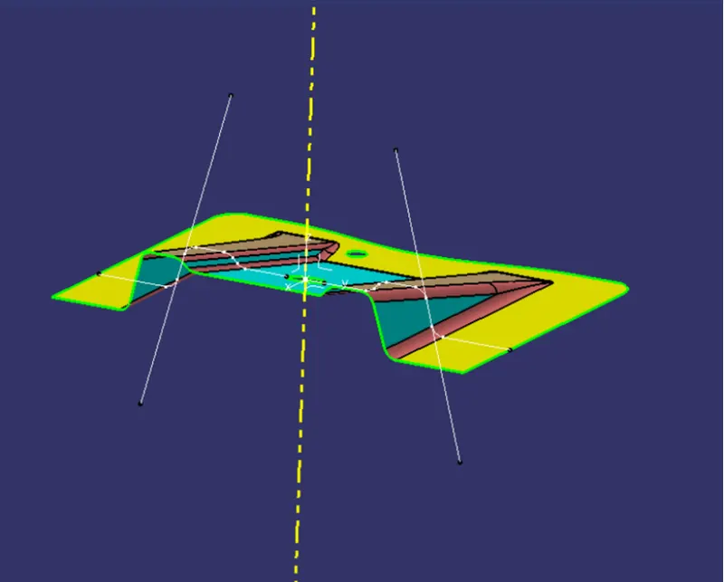
- Create a bisecting line using the line shown above.
- Here, line show in dotted is our tooling axis.
Class-A surface:
Class-B surface:
Class-C surface:
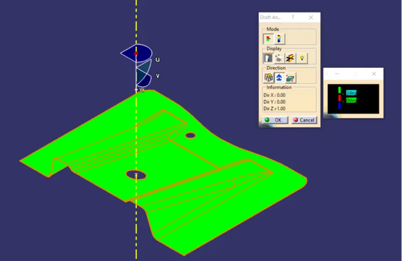
Draft Analysis on the Component:
For this analysis, main tooling axis is taken draft reference and angle is so important. Angle is checking then draft analysis.
This model is 3-degree less than angle for Edge. So draft angel is 3.
Results:
Close surface: