Week 9 - Challenge 1 - Base Bracket Design
Week 9 - Challenge 1 - Base Bracket Design
In this challenge a Base Bracket plastic component is created with thickness of 2.5 by considering the given class-A surface and then modifying it to class-B, class-C and then to a Solid body.
Tooling axis
From considering class-A surface a Tooling axis is created. Tooling axis is created by viewing the surface from all 3 axis. And the axis from which the maximum surface area including the Bosses, Pockets and Holes etc is visible that axis is taken as Tooling axis.
The Tooling Direction is basically the direction that the mold pulls apart. The mold is built in two separate pieces, basically. You have a Cavity side and you have the Core side. The Core pulls apart from the Cavity and that's the Dyeline or the Tooling Direction. Again, depending upon where you're working at, you may have a different name for it. So, when you go in and you create that Tooling Direction, you want to make sure that whatever you create is going to be used as a reference to design your data up against. So, when you add in your ribs, maybe some pockets, walls, whatever that may be, bosses, the walls are going to be drafted based off of the Tooling Direction. It's to make sure that the Core can pull apart from the Cavity, nice and clean.
Creating Tooling axis by Bisecting method
In this challenge the given surface having maximum uneven face, bosses, and holes can be visible by viewing from top direction (i.e. from Z axis direction). The tooling axis is not restricted to a particular direction. It can be produced in that direction where the product can be produced easily. By selecting the effectice Tooling axis we can reduce the number of side cores.
The Tooling axis can be created by diferent ways among which Bisecting method is one of them. In Bisection method, Tooling line is created by bisecting the other lines (maximum draft lines) to a single axis or a point.
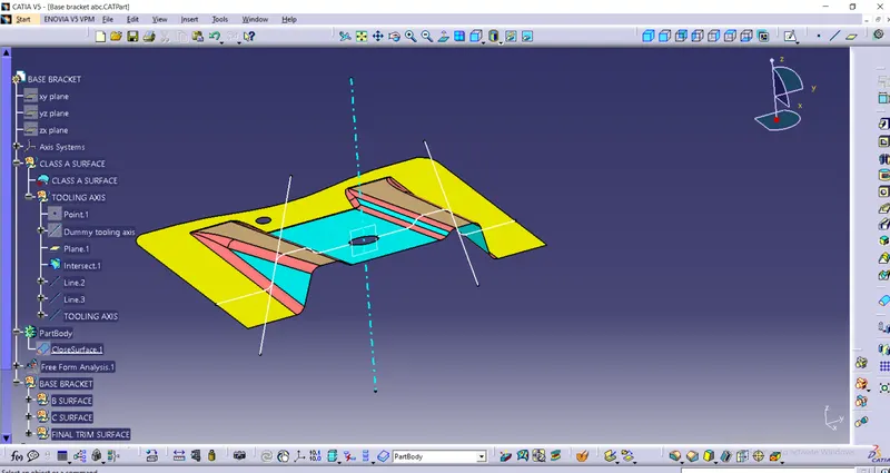
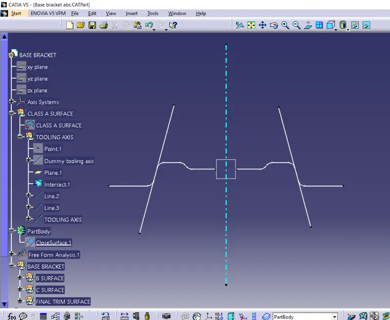
Here in his challenge a plane parallel to the z axis (zy plane) is created on the surface and the outer profile of the surface is made intersect to the plane. Then extending the draft or angled lines to certain length which will be meeting at further length. Then a Bisecting Line is created considering the draft line as reference as shown in below picture. The Blue line is the Tooling axis line.
Draft Analysis
For easy and safe removal of part it is mandatory that the faces should be drafted. The value of draft angle is provided by considering the length or depth of the face. So atleast 1 to 2 degree draft should be given and to ensure the proper draft angle we do the Draft analysis by checking each faces.
To activate the draft analysis function we need to go in Wireframe or Generative shape design workbench and then then in tools and in analysis. Or by selecting it from Analysis toolbar.
After clicking on the draft analysis we would find an error of the material mode which can be solved by selecting the costomize view material in the shading views toolbar (icon with Question mark sign). After selecting the material mode the Draft analysis pop up will be appeared as shown below.
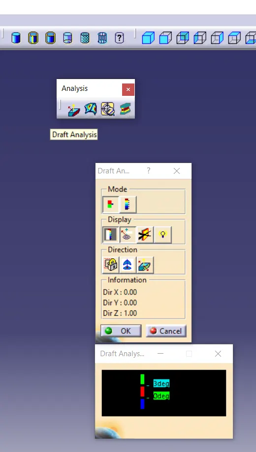
After getting the Draft analysis dialog box click on the first button in Display section which shows the second dialog box of color lines and degree values below that. After that we need to align the Compass direction with the Tooling axis. To do that we need to select the Compass button (2nd button) from the Direction section.
Then to analyse the draft degree we need to set minimum range of draft angle specified in small Blue and Green shaded rectangles in the display dialog box. The degree marked in Blue represents the mnimum andle value.
Now by clicking the second button in the Display section an indicator appears. So by howering the indicator over the draft faces it displays the angle values as shown below.
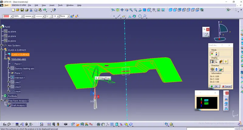
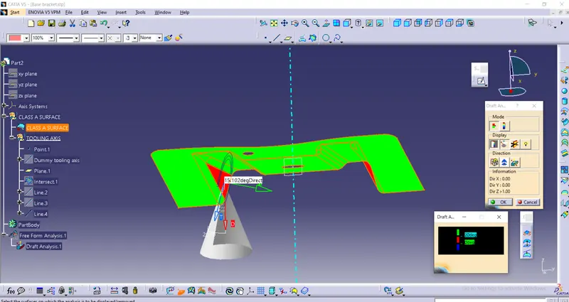
If a face having draft angle lower than the value specified in the blue box then that faces will be marked in Red color as shown in below picture. Here this time the value in Blue box is set to 20 degree and one of the rib face is having only 15 degree so it is indicated in red.
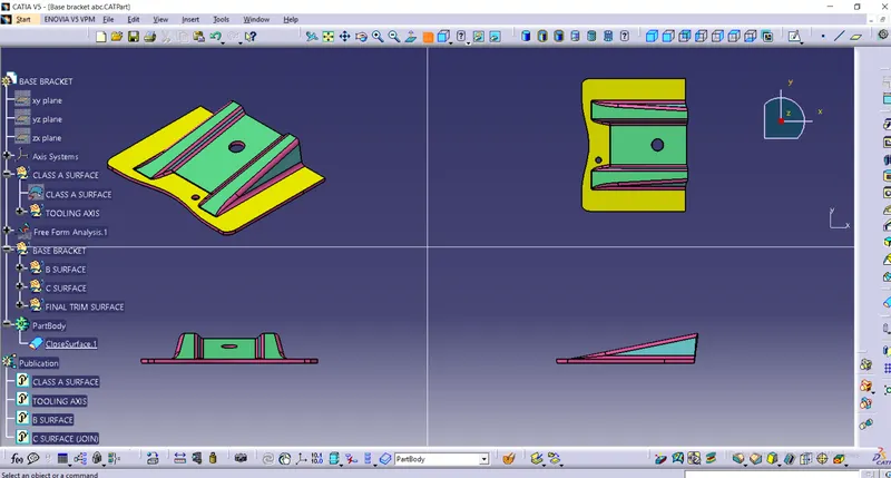
Now after creating the Tooling axis and varifying Draft analysis, a Class-B surface is created by offsetting 2.5 mm the rib and base surfaces then after trimming them to a single part. Then Class-C surface is created by considering the boundary of class-a surface and extruding it with the help of Sweep command in the tooling axis direction. Then class-b and class-c surfaces are trimmed to get a closed hollow surface part having 2.5 mm thickness. This hollow surface part is converted to solid by using Close command. The complete solid model is shown in the below picture.
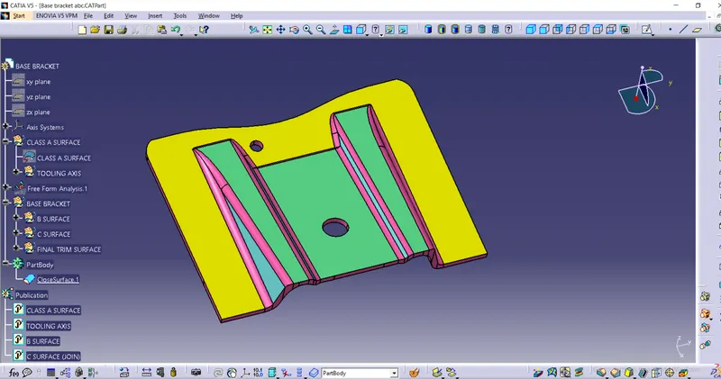
The above screenshot also represents proper Tree structure, names od Geometrical sets and also the Punlication of Tooling axis, Class-A, Class-B, Class-C surfaes.
The image below represents different views of the part. The top left section reepresents Isometric view of the part. The top right section represents Top view of the part. Then bottom left section represents Front view of the part. And the bottom right section represents Side view of the part.