Week 9 - Challenge 1 - Base Bracket Design
Base Bracket Design
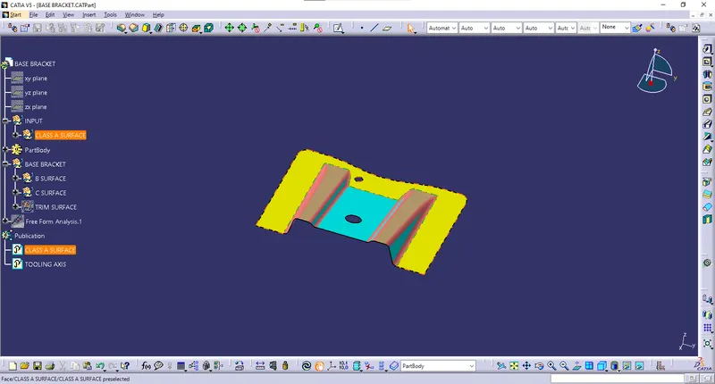
INPUT CLASS-A SURFACE:
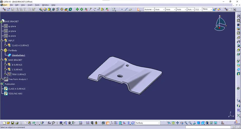
SOLID PART BODY:
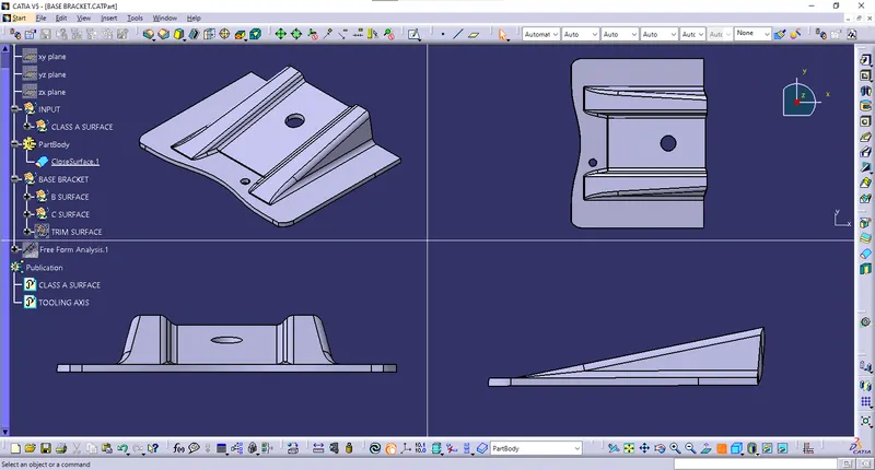
DESCRIPTION:
Four stages of design life cycle are as follows:
Concept sketch:
- These are the imaginative and innovative sketches.
- Concept sketches can be defined as collection of visual cues sufficient to suggest the design to an informed observer.
- These are the basic sketches which provides general idea about design of the product.
- These sketches are provided to system either in 2D or isometric form.
- Example, concept sketch of an automobile.
Class A Creation:
- Class A surface refers to those surfaces which are VISIBLE and abide to the physical meaning, in a product.
- For styling-class A surfaces of automobile ALIAS software is used.
- These class-A surfaces are used as an input for an Automotive Plastic Designers
CLAY MODELING:
- In clay modeling class-A surfaces are provided to clay modeler who design actual model of automobile using industrial clay.
- Class-A surfaces and clay models are co-related.
- Using clay modeling physical representation of design is possible which helps in further modifications in the design of the vehicle.
- Clay modeling of an automobile is most common example of a clay modeling.
NPD CAD:
- New Product Development (NPD) Computer Aided Drafting (CAD).
- This process involves forming strategy, organizing requirements, generating concepts, creating product
TOOLING AXIS CREATION:
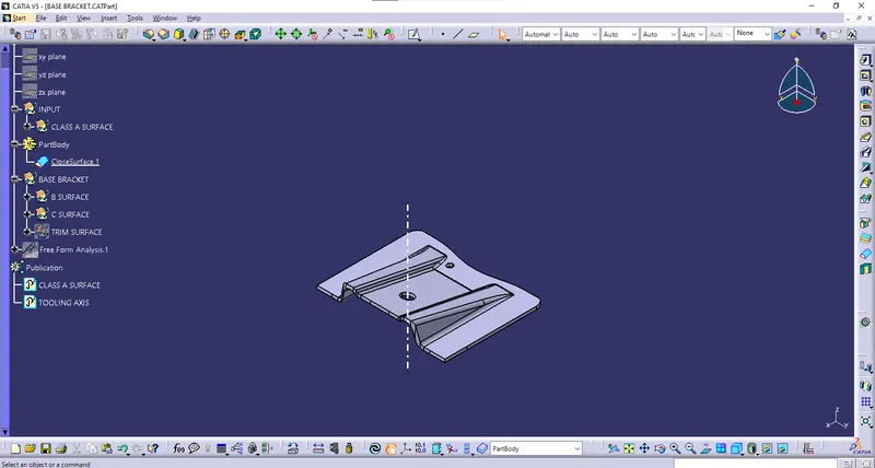
Class-A surface is first analyzed to create tooling axis or tooling direction that molds pull apart in injection molding. Tooling direction is vital for plastic product design as it decides direction for mold separation.
Steps followed for creation of tooling axis:
- Reference point is first created on extracted surface.
- New axis system is deployed to plot clearance lines.
- The X direction and Y direction along the class A were used to create tooling axis
- Two clearing lines were bisected to form Tooling axis.
- Graphic properties of tooling axis were change before publishing.
DRAFT ANALYSIS:
- Draft angles are generally a requirement of injection molding design (though there are a select few soft materials, like nylon, that can get away with draft angles of zero).
- Draft should be a part of design for manufacture, and Plastic Product Designer should be aware of its need at the outset of the design process. This allows considerations for design requirements to be taken into account.

STEPS FOLLOWED FOR DRAFT ANALYSIS:
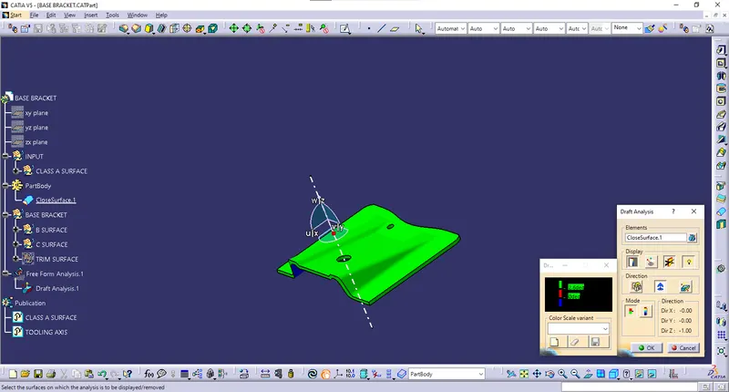
- The part created has to be changed to material mode in display frame.
- Compass is enabled. Align compass along with tooling direction.
- Lock command is then applied to fix compass along with tooling axis
- Color codes are classified and Draft angle is applied.
- Running point analysis is used to display permissible draft angle.
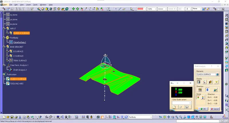
DRAFT ANALYSIS REPORT:
DRAFT ANALYSIS ON CLASS-A SURFACE:
DRAFT ANALYSIS ON BASE BRCKET (FINAL SOLID BODY):
| MAXIMIUM DIGREE IS 3.0 |
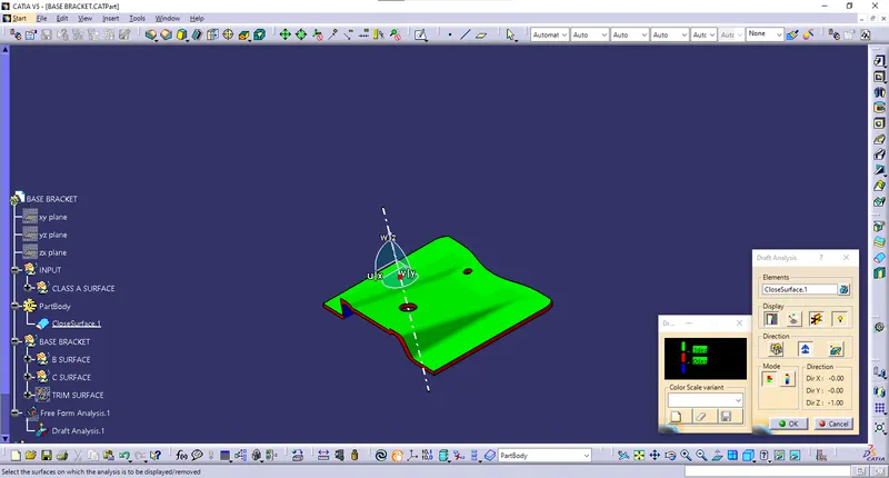
| MINIMUM DIGREE IS 2.6 |