Week 9 - Challenge 1 - Base Bracket Design
BASE BRACKET DESIGN
AIM
To design a base bracket component from the provided Class-A surface.
OBJECTIVE
- To generate a proper tooling axis for the model.
- To perform draft analysis on the Class-A surface.
- To design the base bracket by creating Class-B and Class-C surface.
DESIGN OF BASE BRACKET
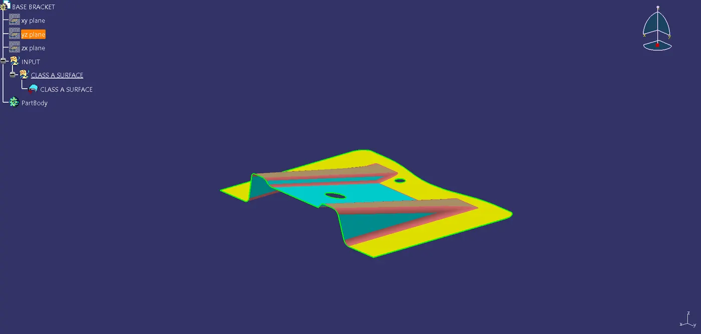
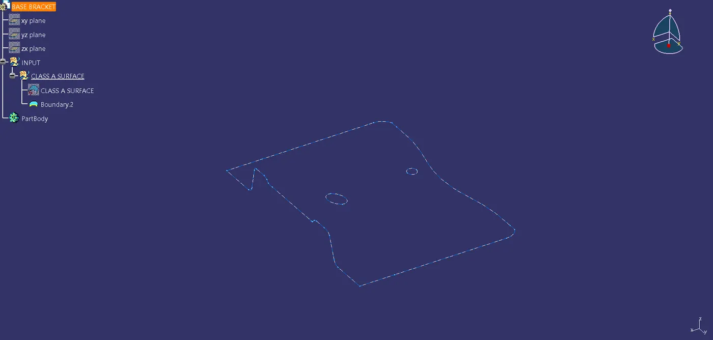
Analysis of provided Class-A surface
- The given surface is imported into Catia and analyzed for any deformities that needs to be addressed.
- All three axis are checked whether there is a suitable tooling axis for the model.
Determination of tooling axis
- The surface is carefully studied and the hole on the surface has been selected so as to generate the tooling axis.
- A dummy axis is created using the circles center.
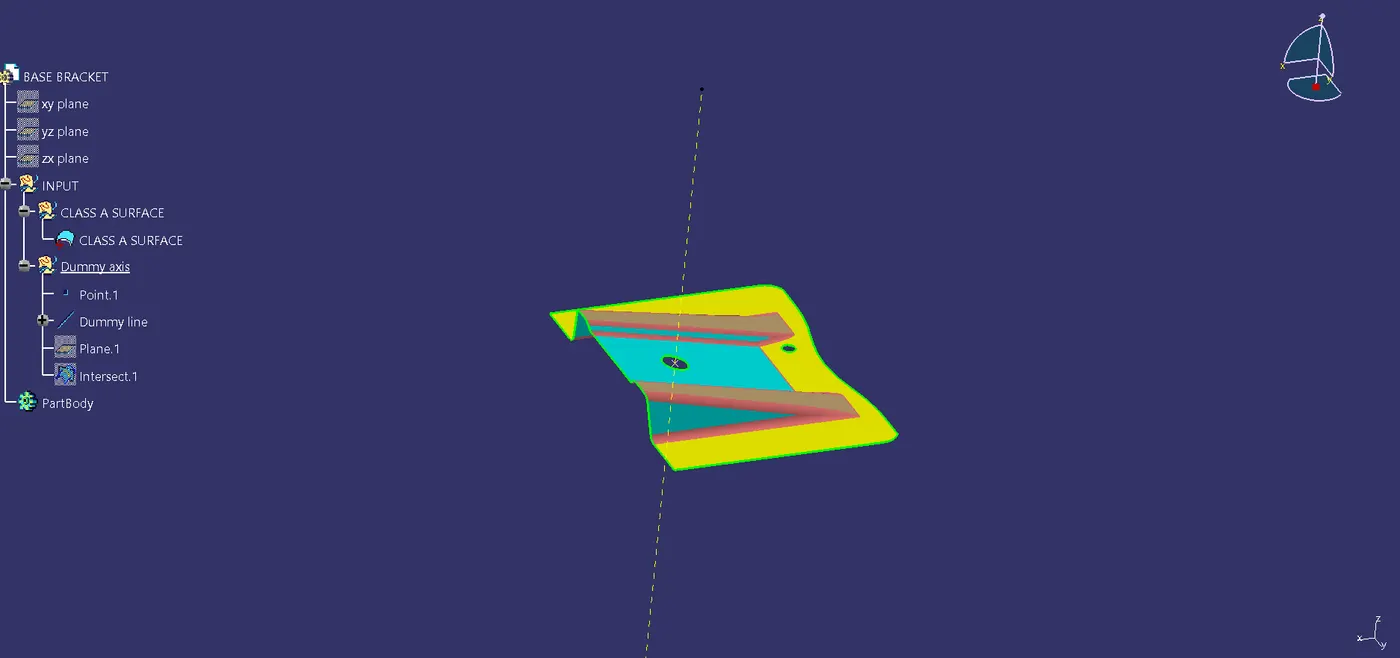
- From the geometry issues may arise from along the XY plane due to the ribs on the model, so an intersection is made with the body and a plane along XY.
- This intersection lines give us an idea about the lines along the curve that are almost parallel to the dummy axis.
- So these lines are extended using their points and line command to generate lines.
- In this case two lines are almost parallel so we generate two lines.
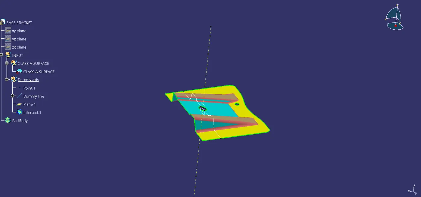
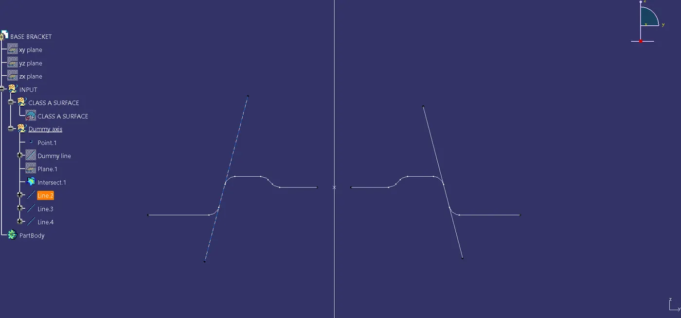
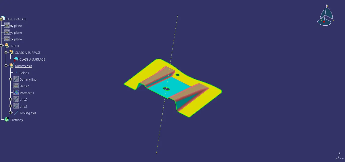
- These lines are bisected using the point made at the center of the circle. This provides us with required tooling axis.
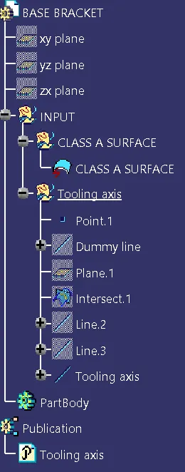
- The tooling axis is published.
Tree structure for tooling axis :
Draft analysis of Class-A surface
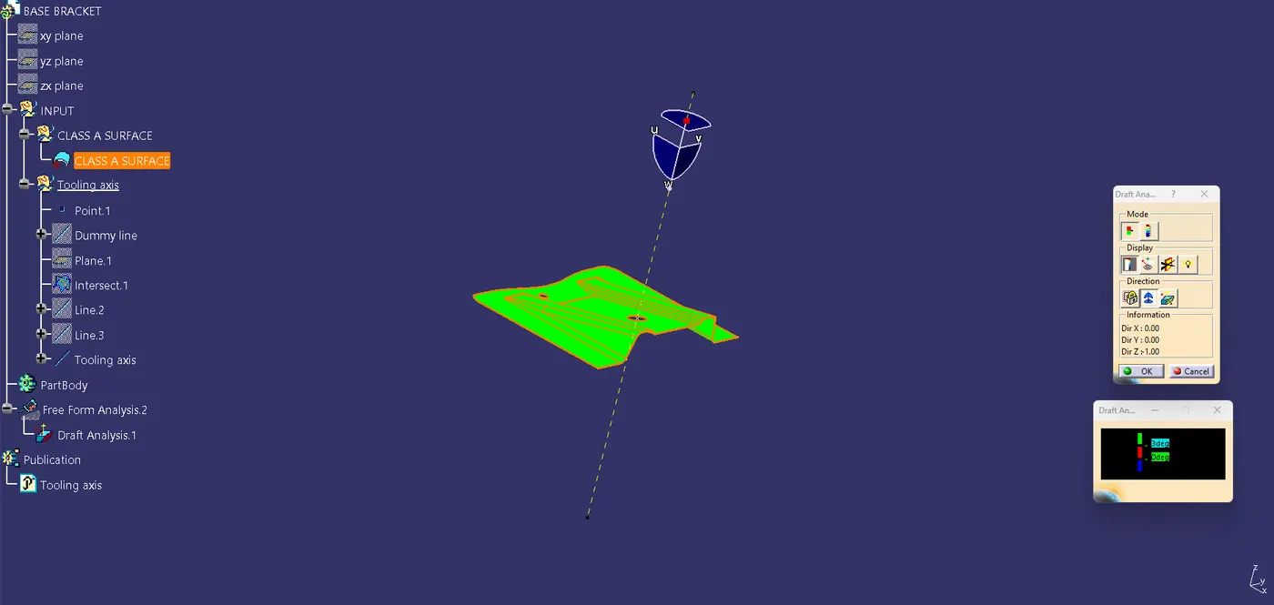
- Feature draft analysis function is used to analyze the surface.
- View mode is set to material in shading tab and minimum draft angle is set to 3 Deg.
- Compass is used to align the axis with the tooling axis for draft analysis.
- Surface is selected.
Modelling of Class-B surface
Modelling of the ribs
- A new geometrical set is created named as "Base bracket", under this another set is created as "Class-B surface", inside of this all the other sets are going to be placed.
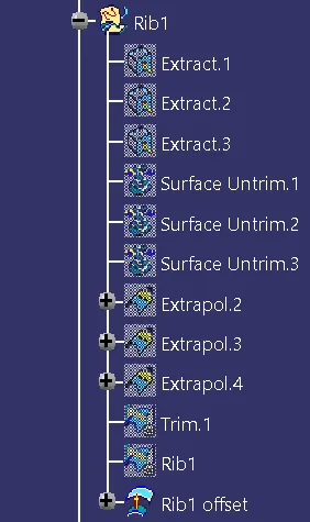
- Starting off with the modelling of the ribs (Fillets are excluded as of now to avoid complications) the required surfaces are extracted using Extract function.
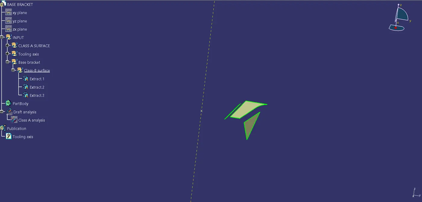
- These surfaces are untrimmed using untrim command.
- These untrimmed surfaces are extrapolated with a factor of 10mm, using curvature continuity, so as they extend and intersect with each other.
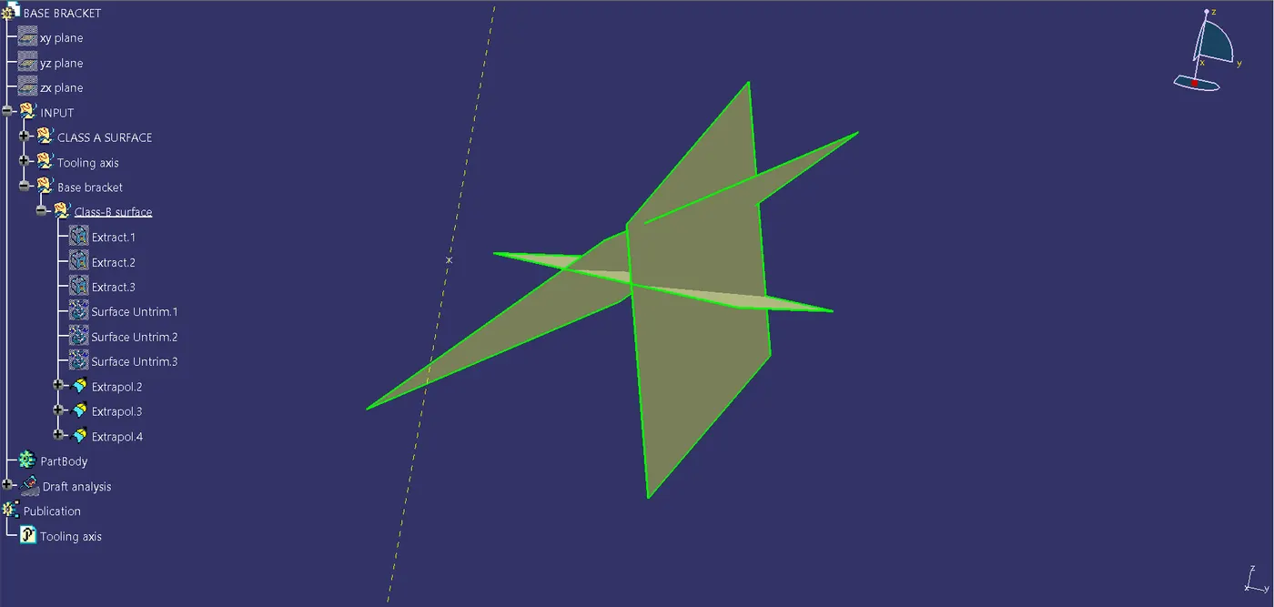
- These 3 surfaces are trimmed so as to obtain a similar structure as in class-A surface.
- The final surface is offset to a distance of 2.5mm (Thickness given).
- All these are grouped and kept in another geometrical set "Rib1".
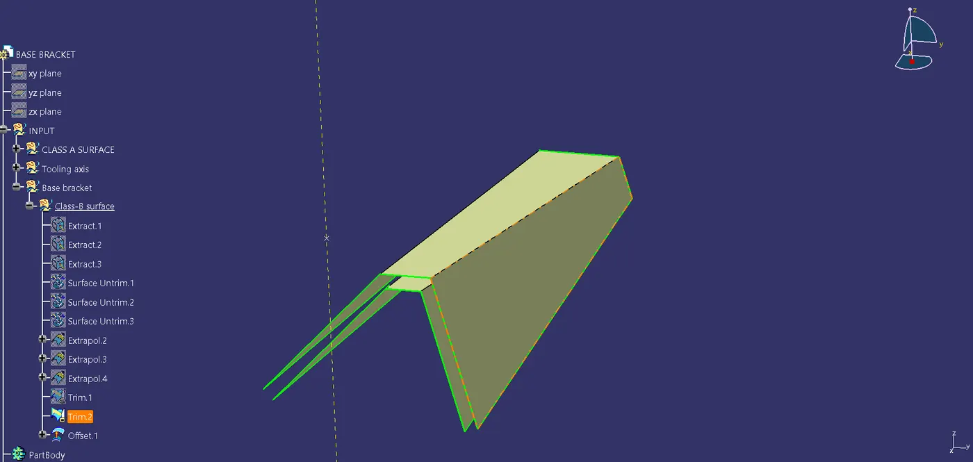
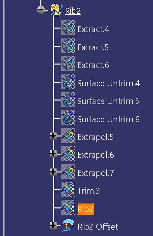
- The same steps are followed to create Rib2.
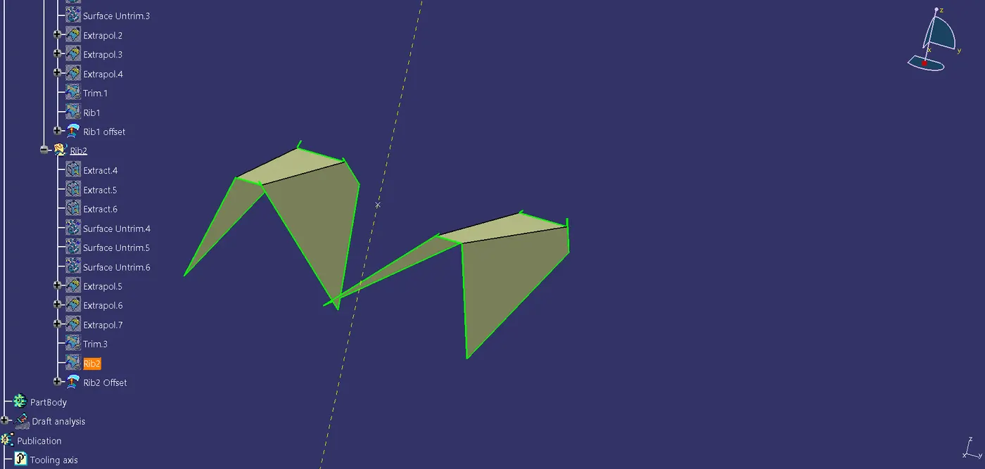
Tree structure for Rib 1 and Rib 2:
Modelling of Base surface
- Base surface comprises of two parts, both the surfaces are extracted separately.
- Both these surfaces are offset to a distance of 2.5mm.
- These surfaces are both untrimmed and extrapolated by a factor of 10mm to intersect with previously created ribs.
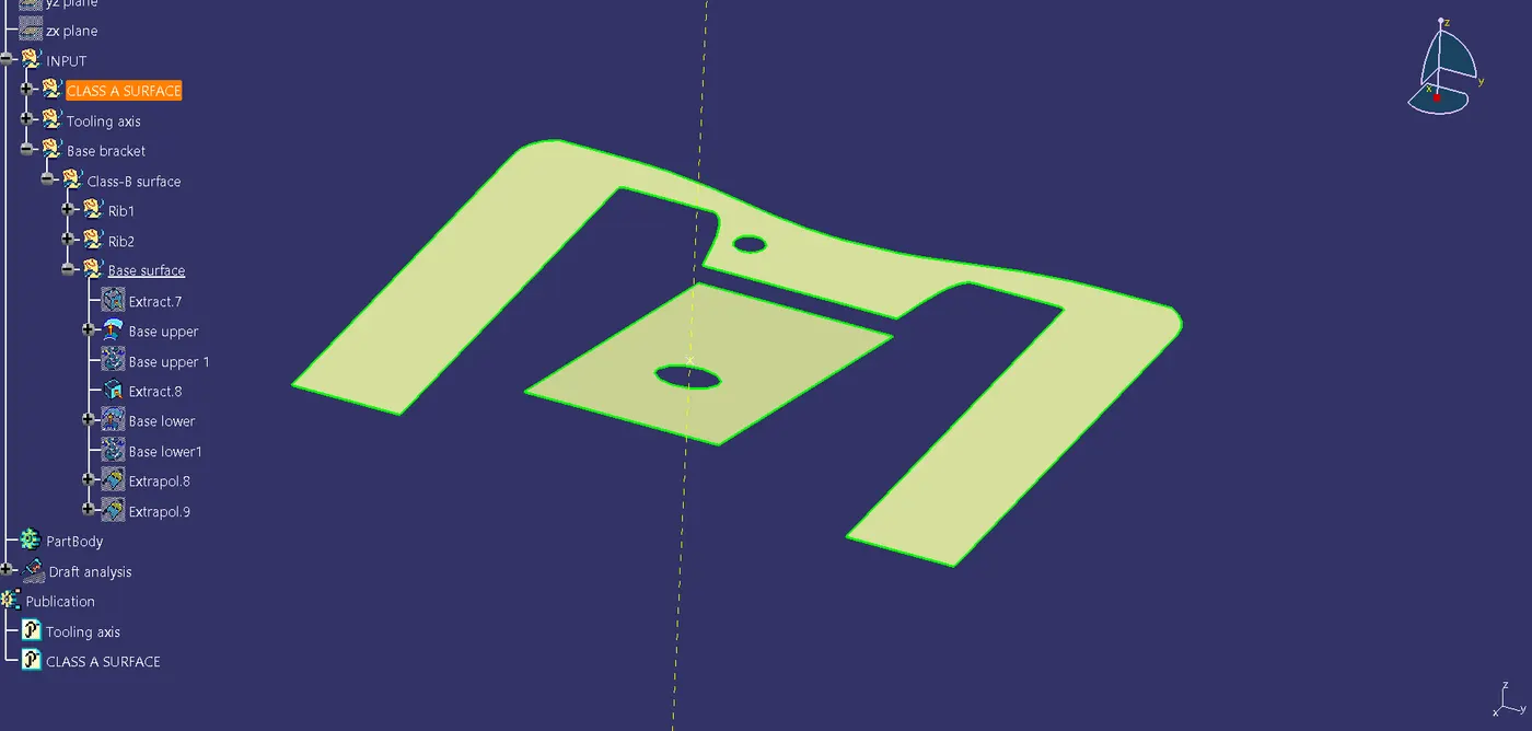
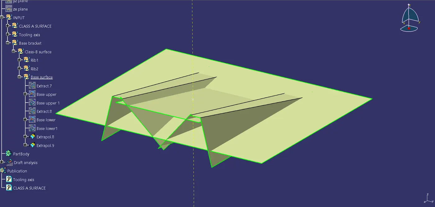
Tree structure for Base surface:
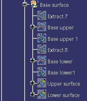
Final B-Surface with fillets
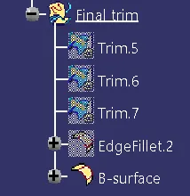
- New geometrical set is created under "Base Surface" as "Final trim".
- The existing two ribs and the two base surfaces are trimmed with each other to result in the final surface or the class-B surface.
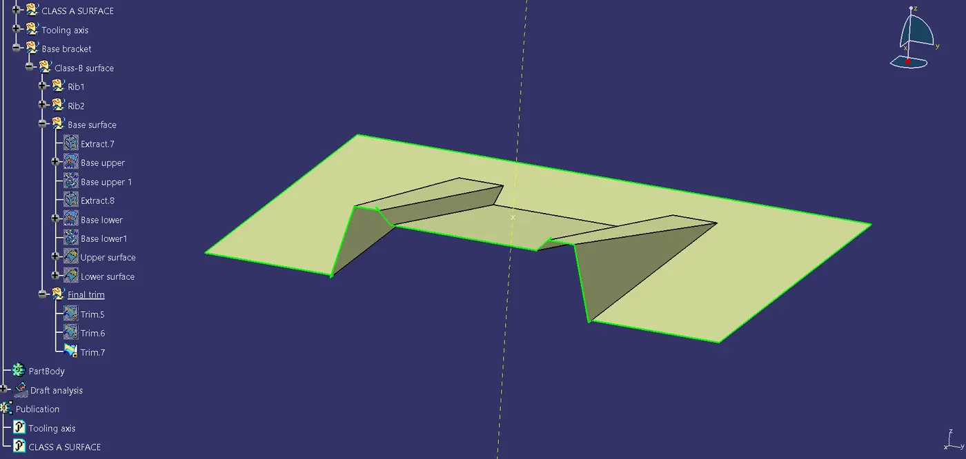
- Upon measuring the class-A surface for fillets we find that all the fillets are of radius 3mm.
- Using edge fillet we provide 3mm fillet radius to the sharp edges.
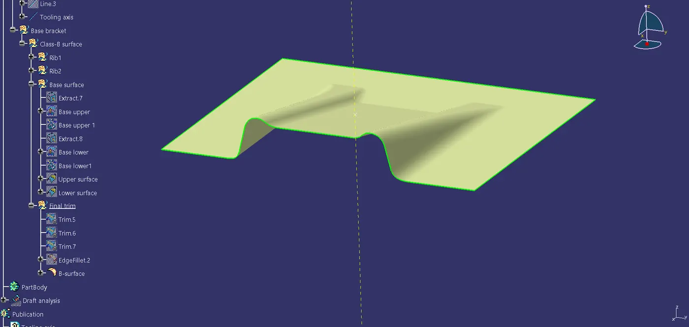
Tree structure for final trim:
Modelling of Class-C surface
- A new geometrical set is made for Class-C surface.
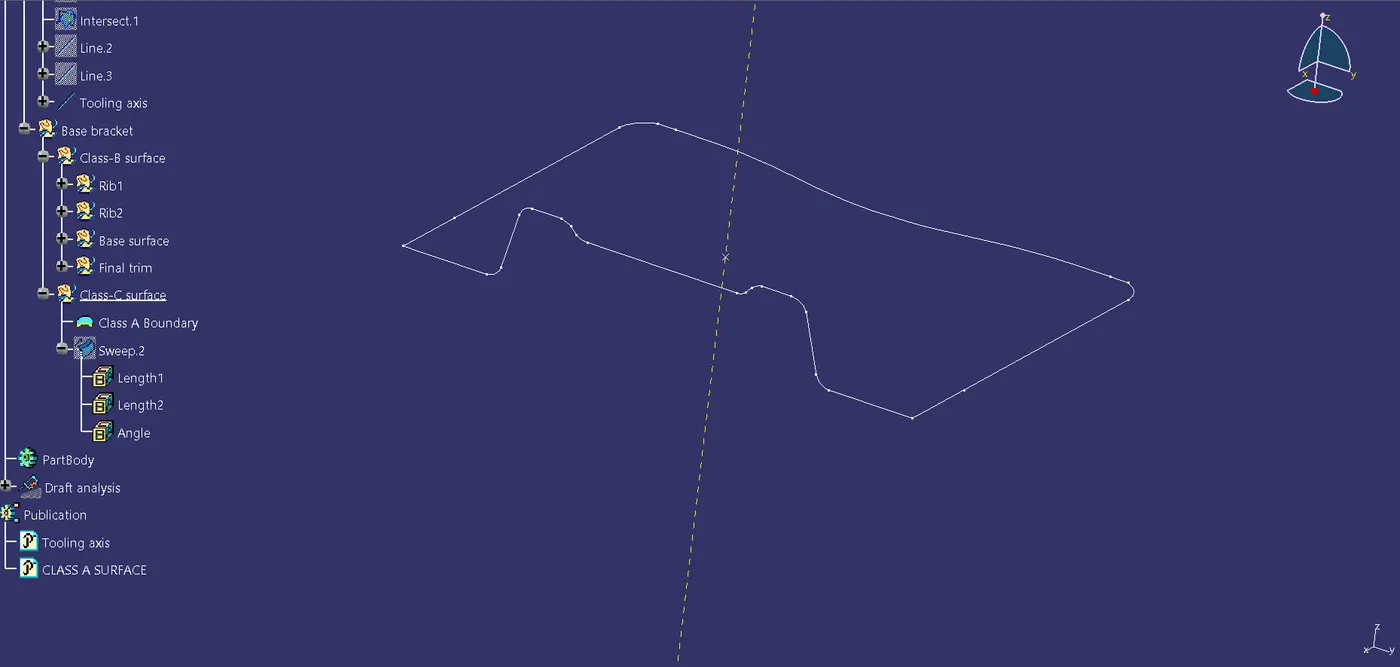
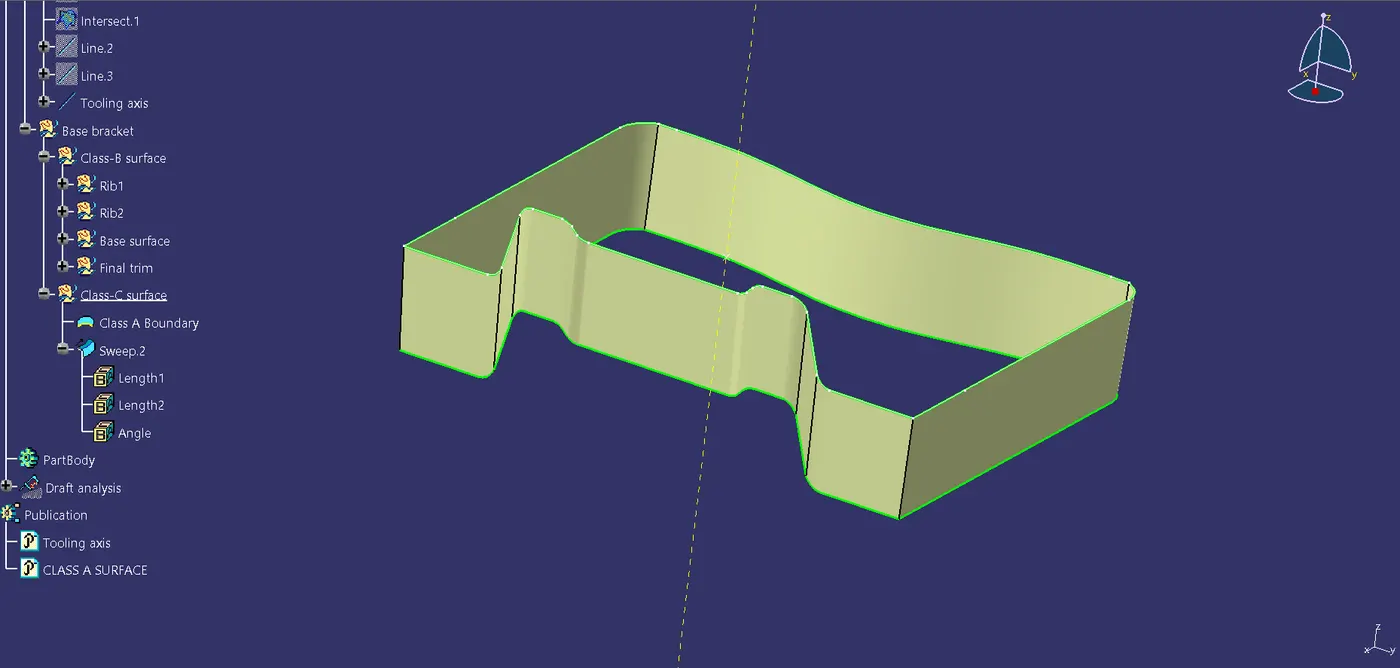
- Here the boundary of the Class-A surface is extracted.
- Using sweep command the boundary is extended along the draft direction, using the boundary as guide curve 1 and created axis as the direction.
- Similarly both the holes on the Class-A surface are extracted as boundary and extended using sweep command.
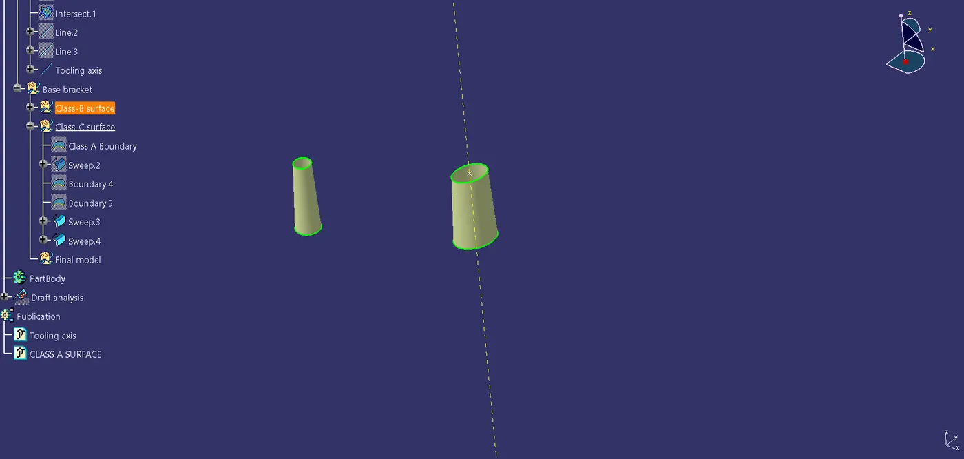
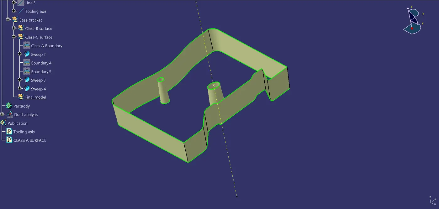
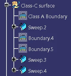
Tree structure for Class-C surface
Final Model
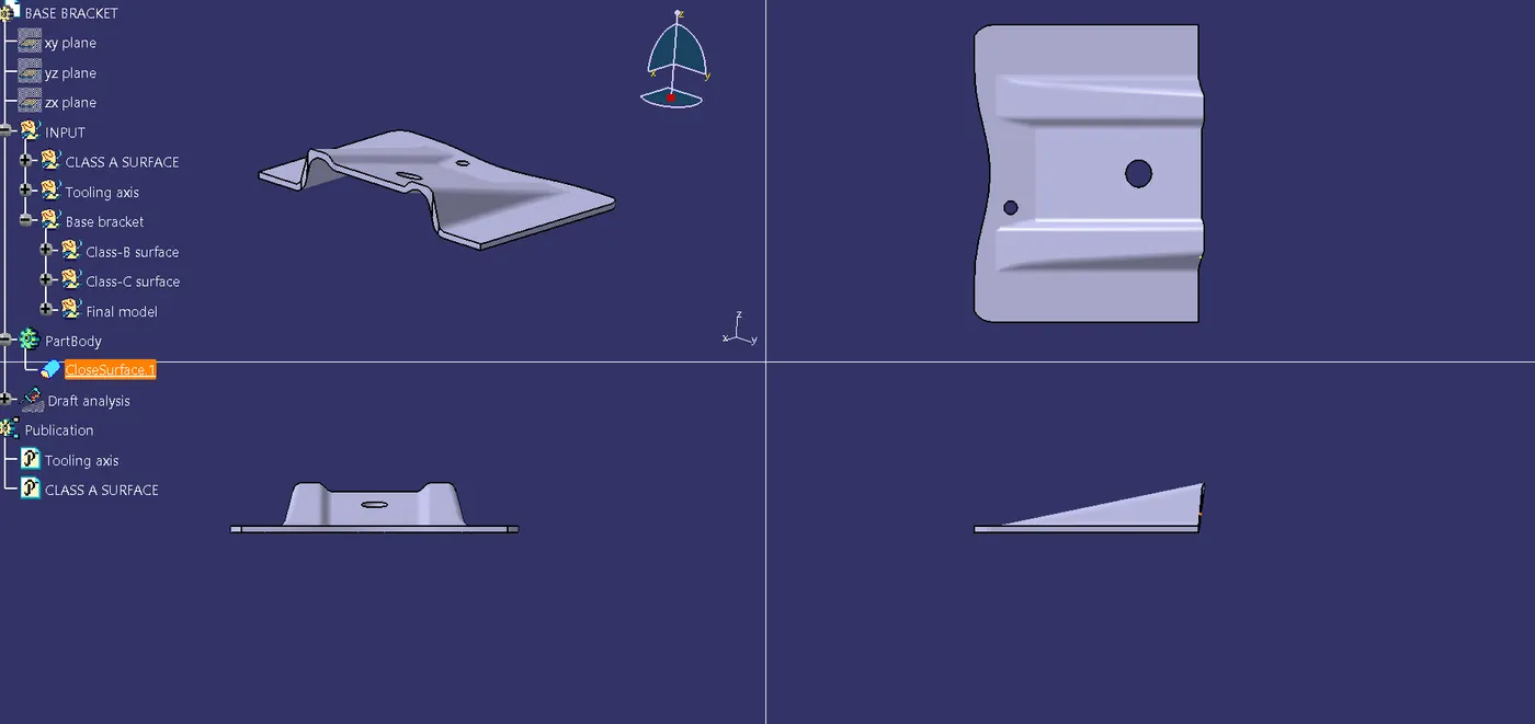
- The final design is created by using the three Class-A, B & C surfaces.
- The Class-A and C surfaces are first joined together.
- From this surface B is trimmed to reveal required model.
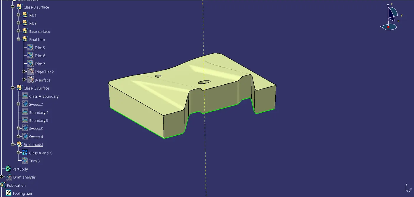
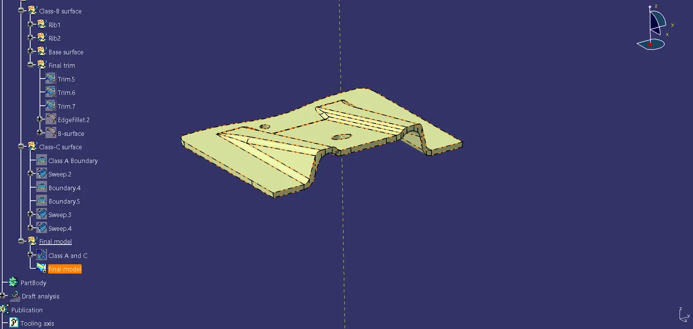
- Using Closed surface command from part design we are able to provide a solid body from the surface.
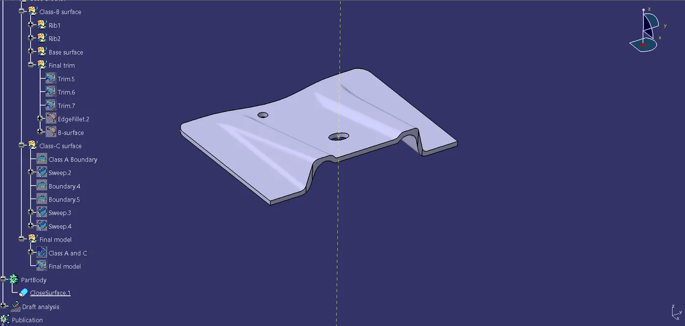
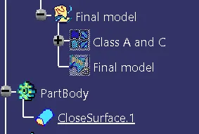
Tree structure for Final model:
Final Product