Week 9 - Challenge 1 - Base Bracket Design
Aim:- To design the Base Bracket plastic component using the given Class-A surface.
Objective:-
- To create a proper tooling direction.
- To perform a draft analysis of the plastic component.
- To design the base bracket plastic component by creating the B-Surface and C-Surface using the given Class-A surface.
Tooling Direction :-
The tooling axis is the direction in which the mold or core and cavity open. Tooling axis or direction is important for plastic component becuase the draft is added to a component along the tooling direction of the plastic component and draft is very important in order to create a part manufacturable. Without the draft it is difficult to eject or no ejection at all of a part from the mold due to srinkage of the part to the mold.
There are many ways to find out the tooling direction and for this base bracket project I am finding out tooling axis using bisecting method.
Before finding a main tooling direction I have created a dummy tooling axis along the Z direction of the Class A surface and reason behind using the bisecting method becuase the 2 surface along the Y direction seems to be parallel to the dummy tooling axis (Z-axis) so I have to check weather these 2 surface will clear the draft analysis along the Z direction.
Procedure to create the tooling axis using bisecting method :-
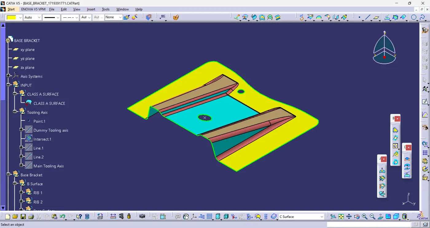
following Class A surface is provided as a input to design the base bracket plastic component-
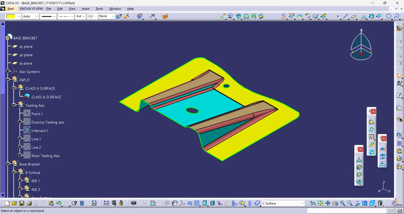
Point is created at the centre of a large hole as shown below-
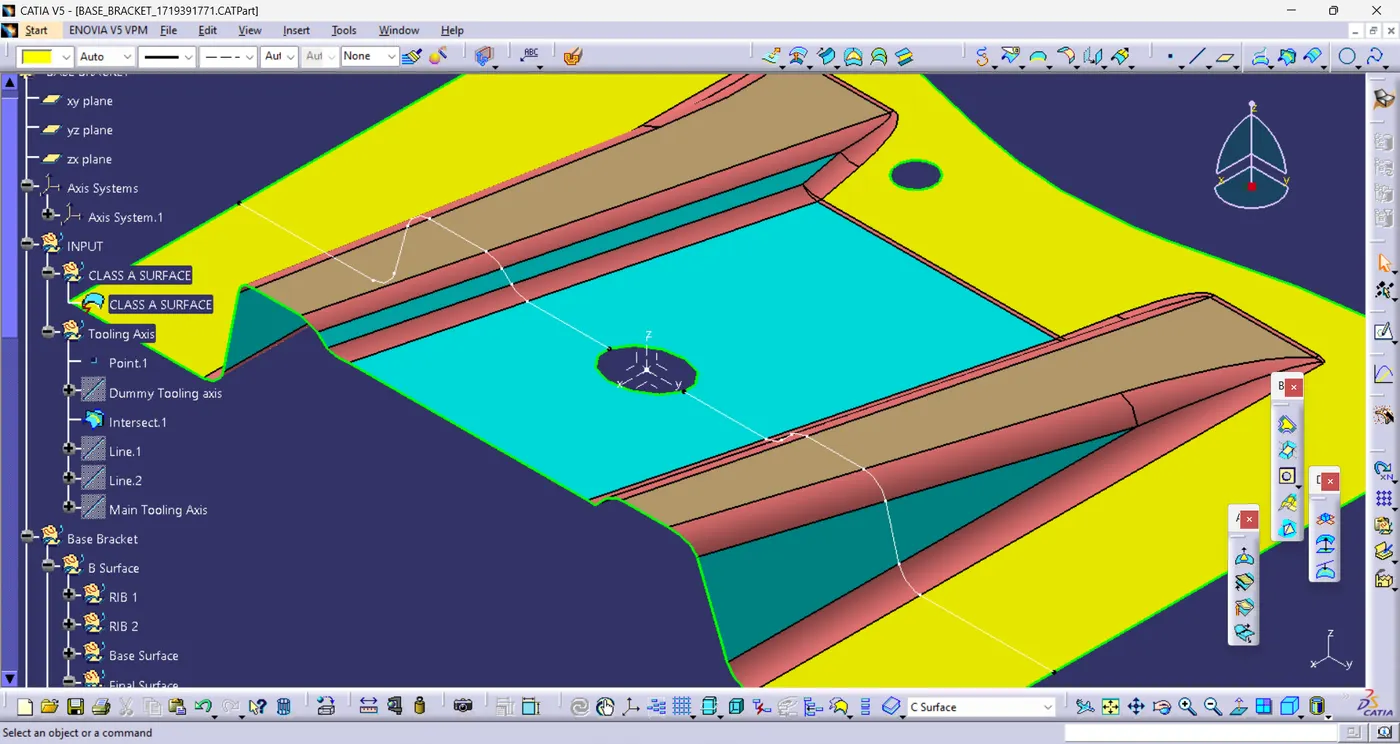
An axis system is created at the center point and YZ plane is used to intersect the class A surface and the intersection is created along the Y direction in YZ plane-
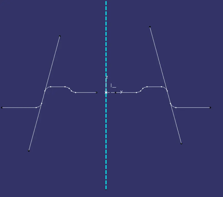
Lines are drawn to the side faces of the intersected curves then bisecting line is created between these two lines-
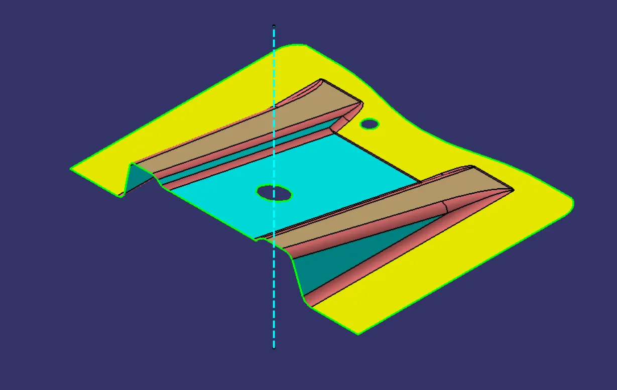
This is main tooling axis-
Draft analysis :-
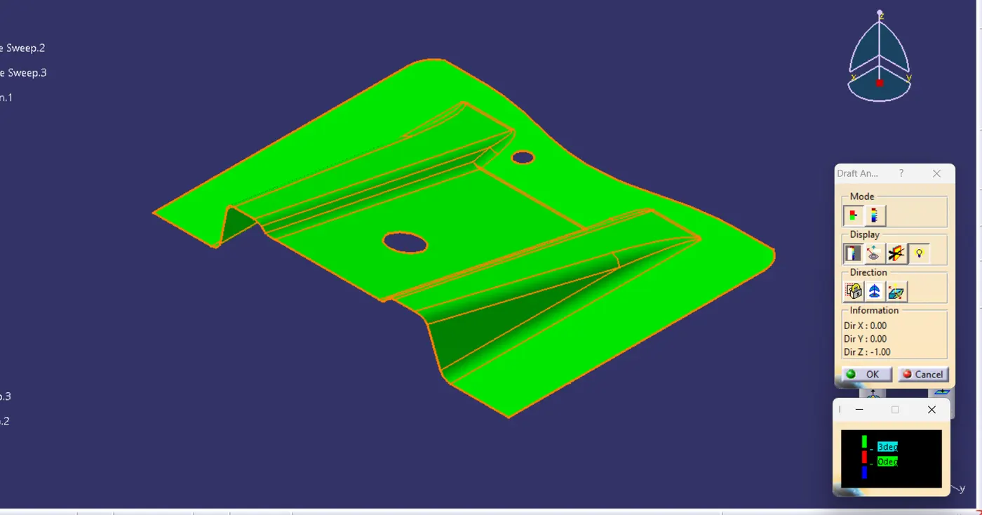
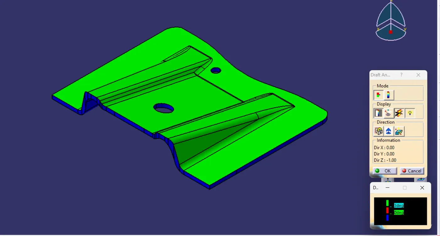
It is recommended to add a minimum of 0.5 to 1 degree upto 3 degree of the draft for non-textured surface & 3 to 5 degree of draft for textured surfaces. Draft analysis is carried out by the draft analysis tool. The tool has a colour range window in which the different colours are defined to represent the different ranges of the draft in a component. In this Base Bracket the minimum draft required is 3 degree, above this 3 degree of draft if the component has more than 3 degree of draft so it will show green hence the Class A surface is clear for tooling.
Class A and B surface-
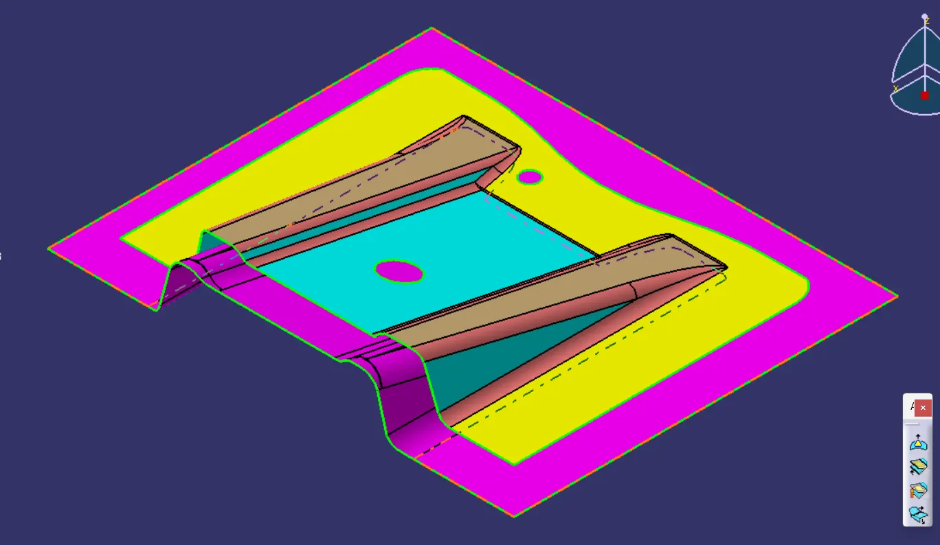
Class B surface is extracted form the class A surface and is offseted 2.5mm below the class A surface in order to create a uniform thinkness of the component. The engineering features are added to the class B surface.
Class B surface is below the class A in pink colour as shown in the picture-
Class C-Surface :-
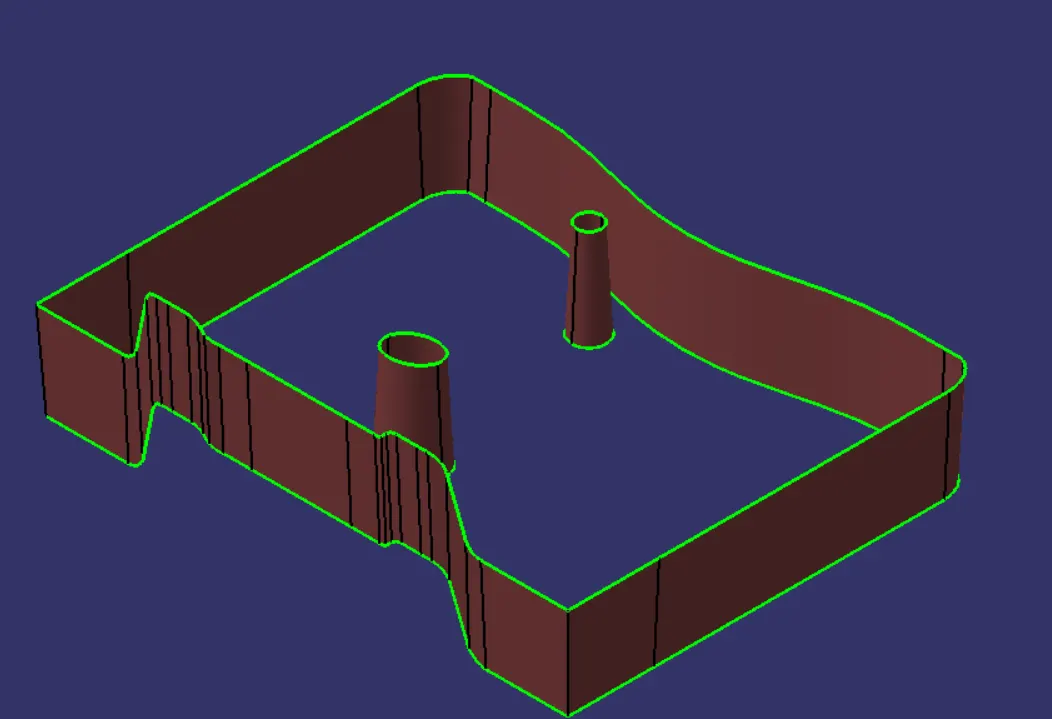
C-Surface connects the class A-Surface and B-Surface. It is created using Sweep command. Boundry of the class A-Surface is swept along the draft direction (tooling direction). Picture below has 3 class C surfaces-
Class A and class C surfaces are joined togather so that there are no gaps or open boundries in between the surfaces-
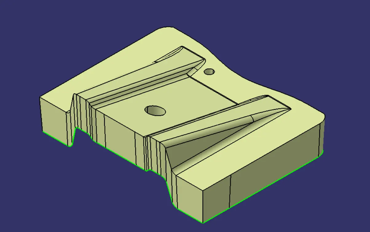
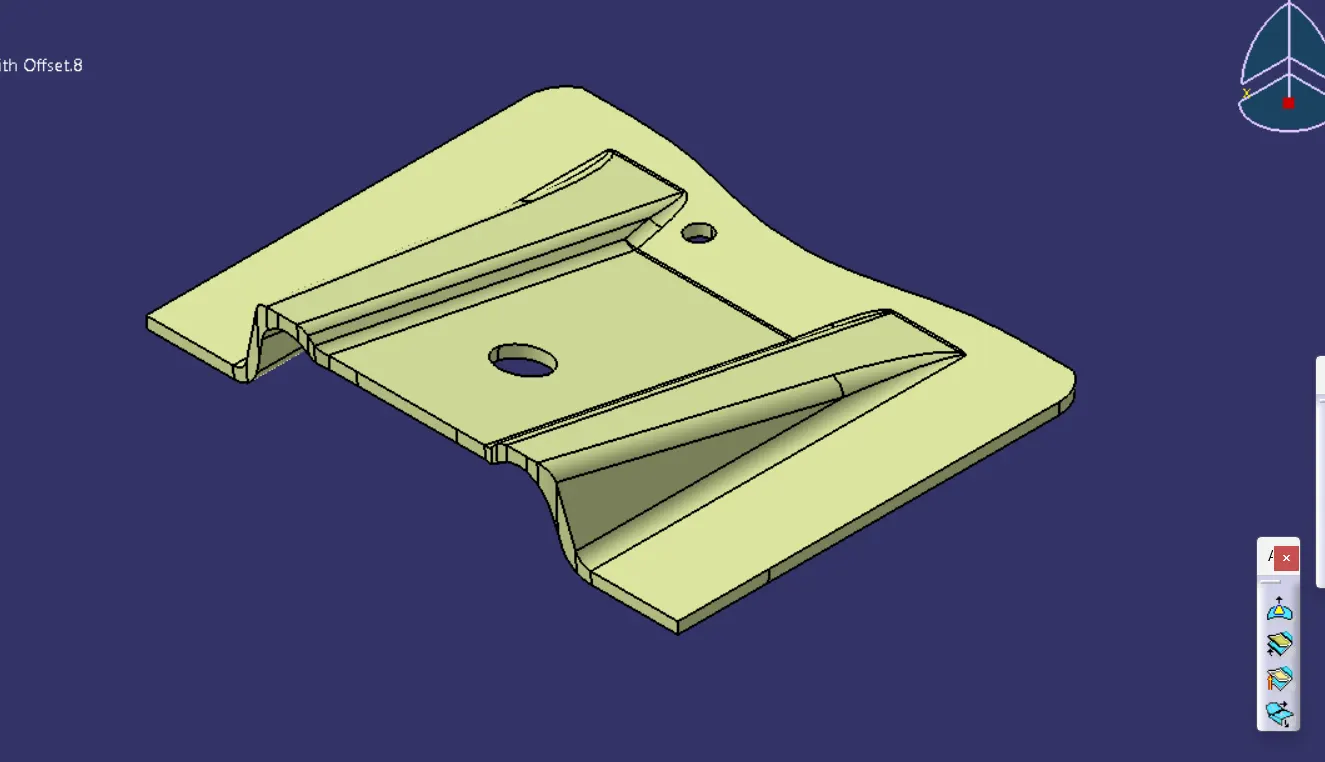
Class B surface and join of class of A and C id trimmed to create final surface-
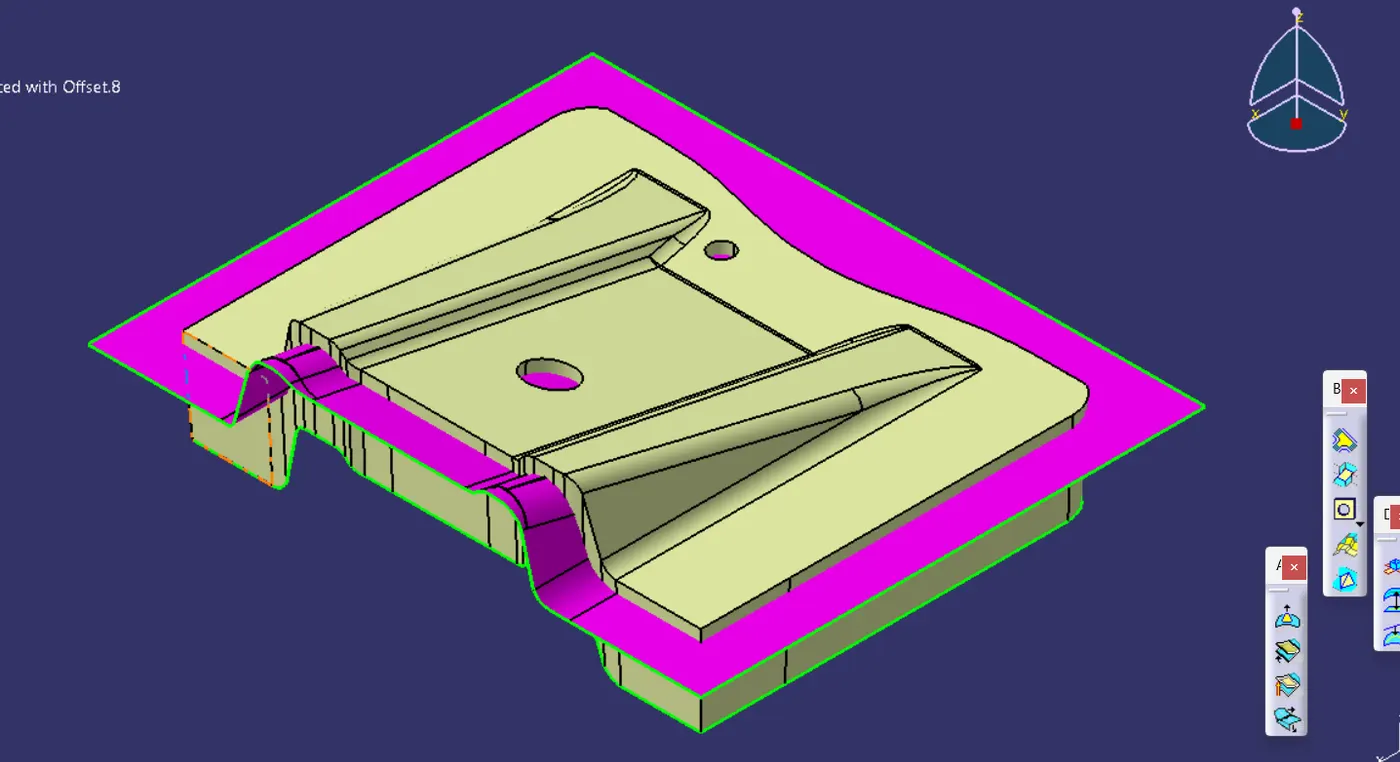
Final surface-
Close Part draft analysis-
Where the blue colour start on the part is where the parting line of the component is, the green portion repersent the cavity side and the blue portion repersent the core side of the component
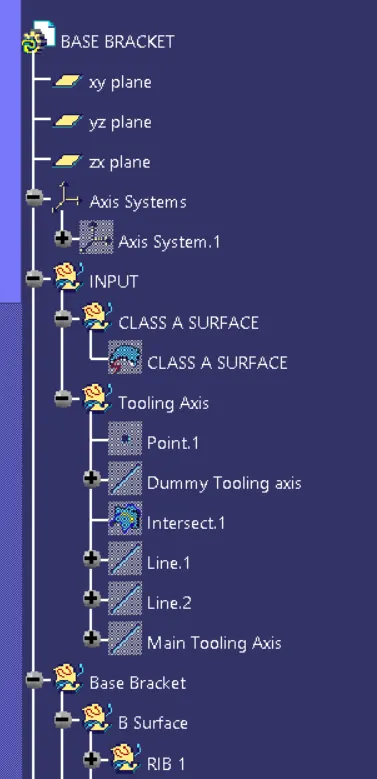
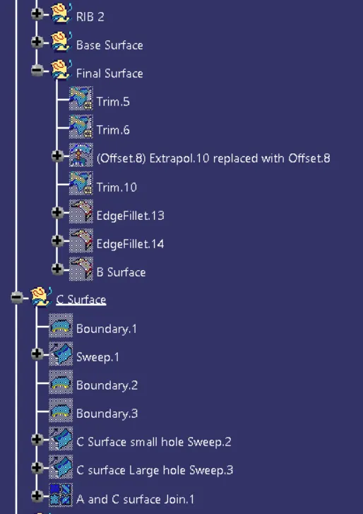
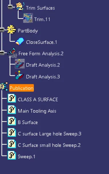
Tree structure-