Week 9 - Challenge 1 - Base Bracket Design
AIM: To create the Base Bracket Plastic component through the given Class-A surface
GIVEN:
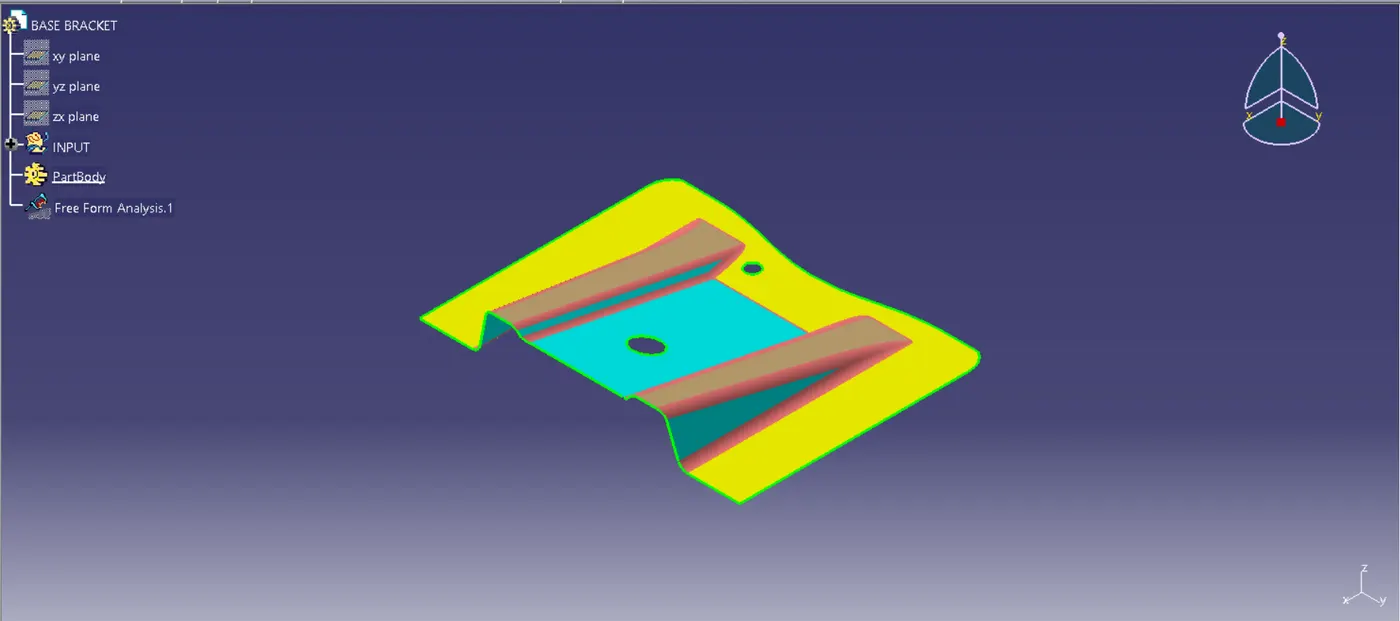
A Class-A surface was given.
INTRODUCTION:
Class-A Surface: A surface created by the designer and provided to the plastic modeler as an input. It is the outermost surface and an aesthetically pleasing one.
Class-B Surface: A surface is classified as class B if its thickness is less than that of a class A surface. This surface is where a model's engineering components are located.
Class-C Surface: A class-C surface is one that connects class-A and class-B surfaces.
METHODOLOGY:
1. For Tooling Axis
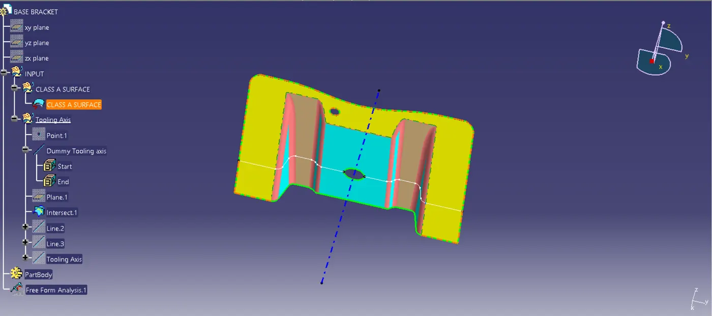
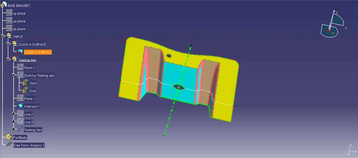
- At first, the connectivity of the Class-A is verified to ensure there is no gap in between. Then, the tooling axis is figured out based on the best possible axis among the three axes. The tooling direction is the direction in which the mold opens or closes. In this assignment, the Z axis is the suitable tooling axis. The Tooling axis is created using the Bisecting Method. The bisecting method is basically used to find the proper tooling axis using the dummy tooling axis.
-The figure below shows the bisecting lines and the Dummy tooling axis.
-The figure below shows the Tooling axis.
2. For Draft Analysis:
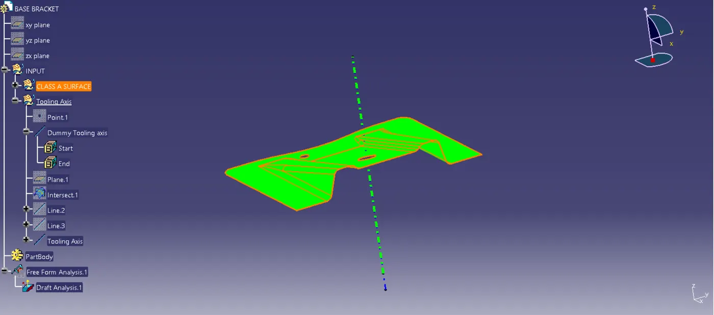
- Go to insert<analysis<draft analysis.
- Then, align the tooling axis with the compass and make sure the surface is within the permissible limit of draft values.
- The surface should be green, and the draft value of 3 degrees should be inserted.
3. For Class-B Surface
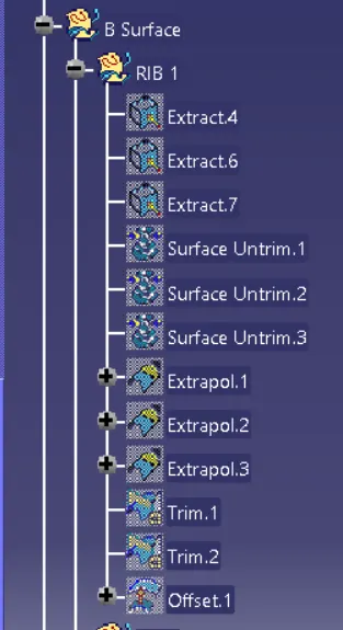
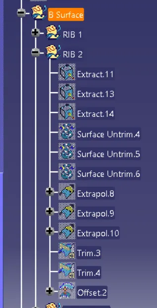
- First, Extract the Rib surface.
- Then, Un-trim the surface.
- After that, Extrapolate it as shown in the picture below.
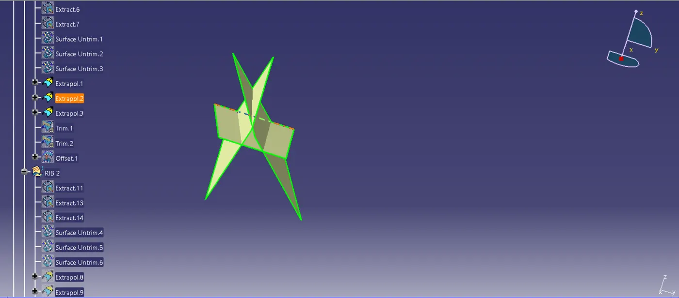
- Trim the surface and offset it by 2.5 mm. The picture below shows one rib and the same process followed for another rib.
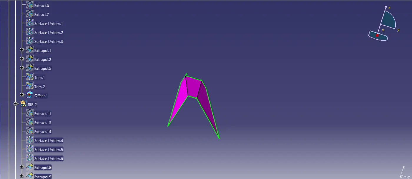
- Picture showing the Ribs.
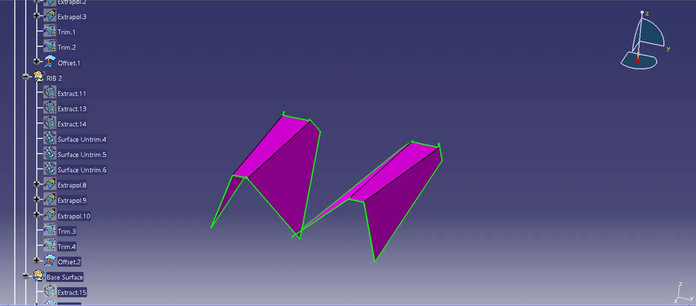
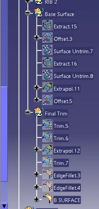
- Extracting the base surface, extrapolating and offsetting it by 2.5 mm.
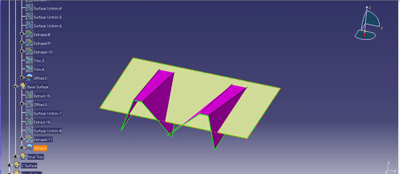
- Final Class-B Surface.
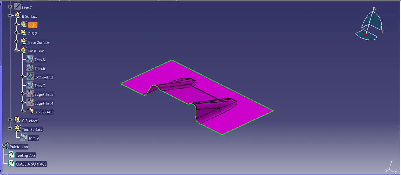
4. For Class-C Surface
- Extracting the boundary of Class-A surface.
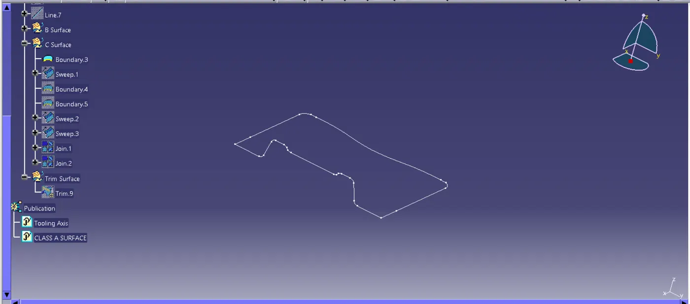
- Extracting the boundaries for holes and using sweep command on boundaries to get Class-C surface
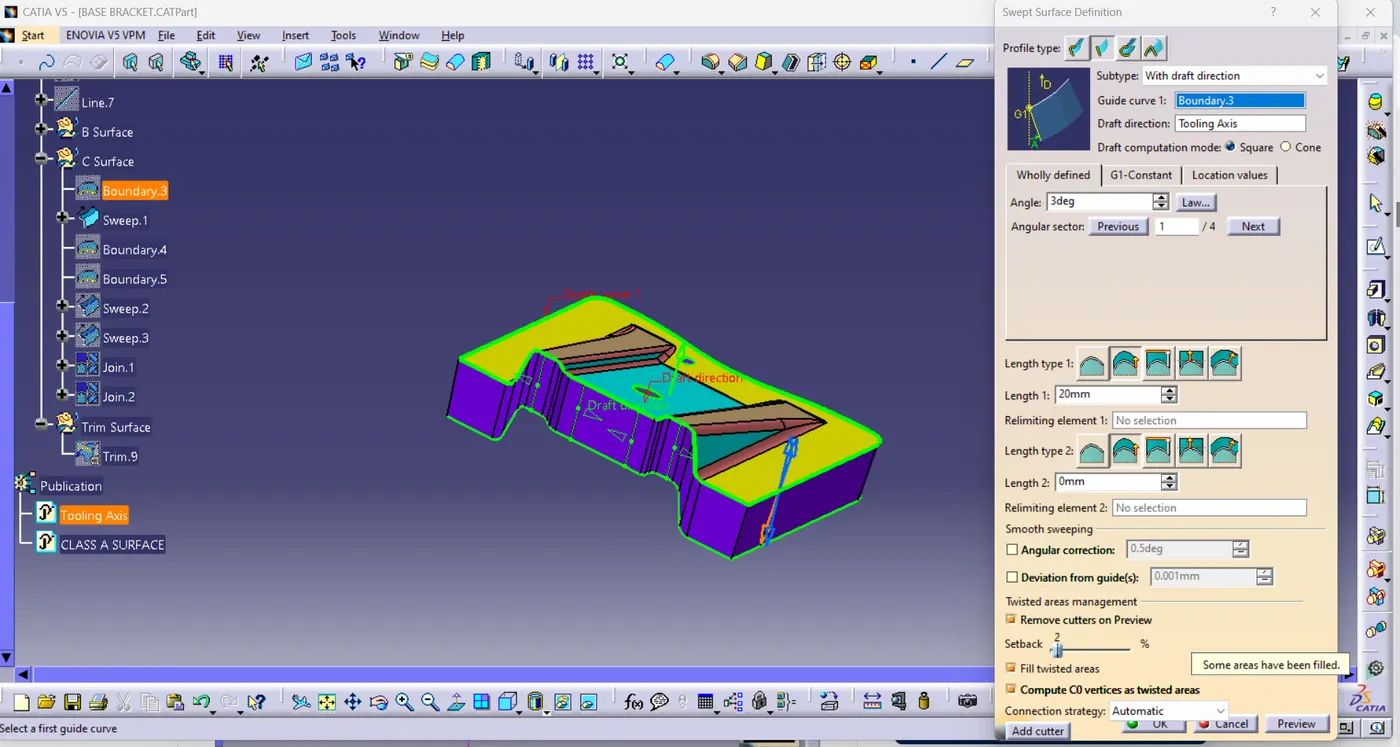
- The Class-C surface.
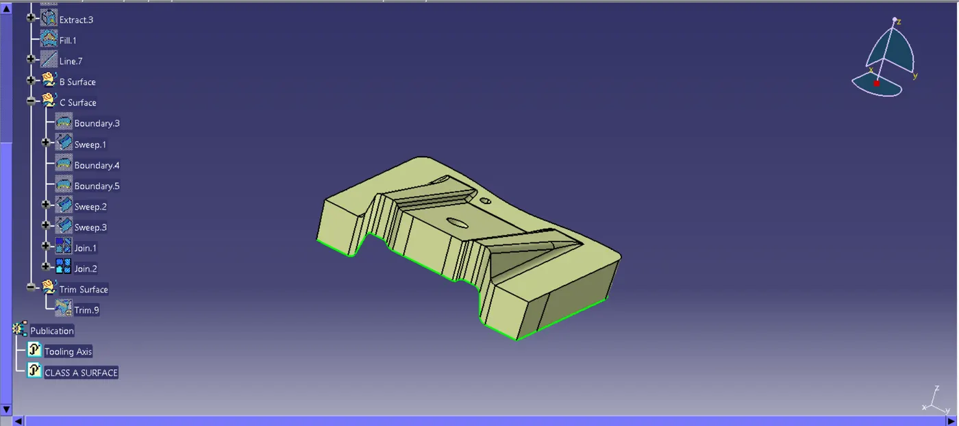
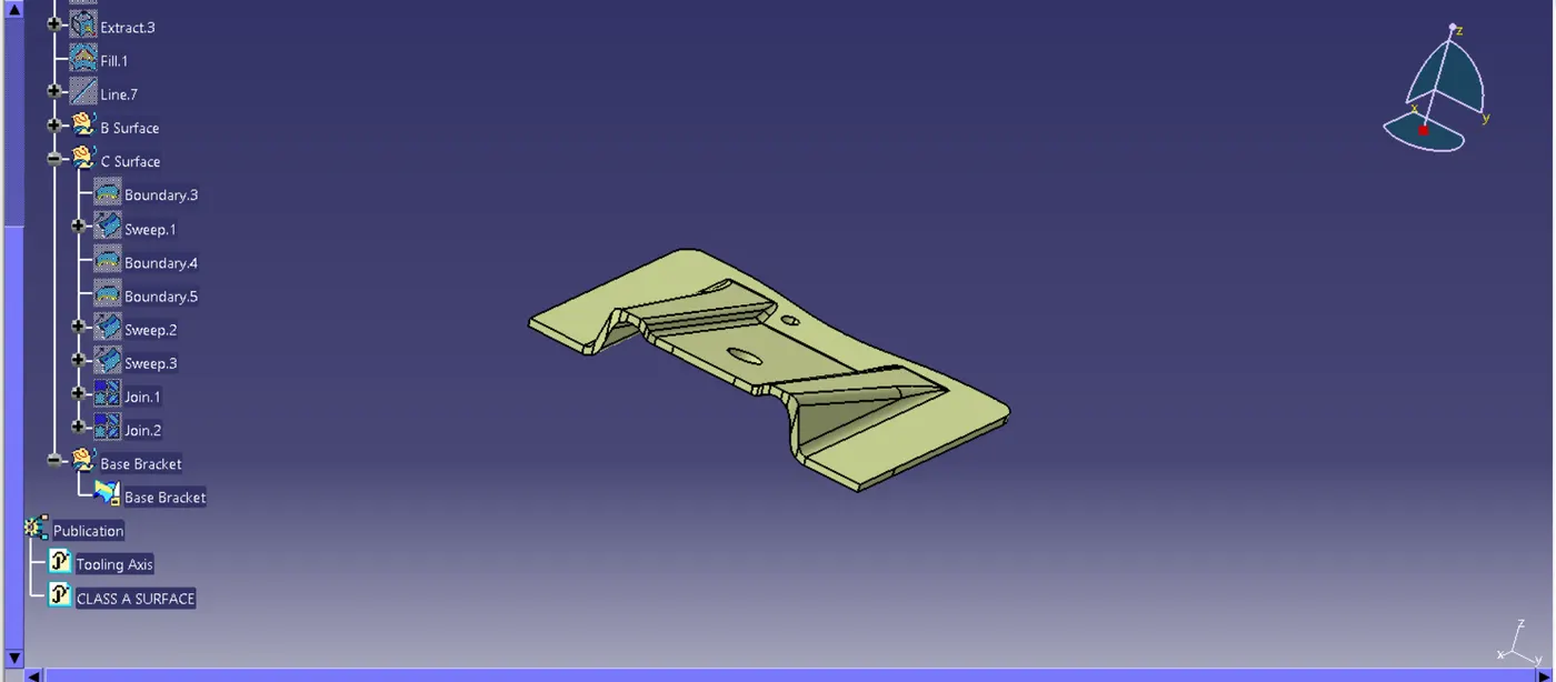
5. Final Base Bracket
- Join the Class-A and Class-C surfaces together and time the Class-B Surface from that.
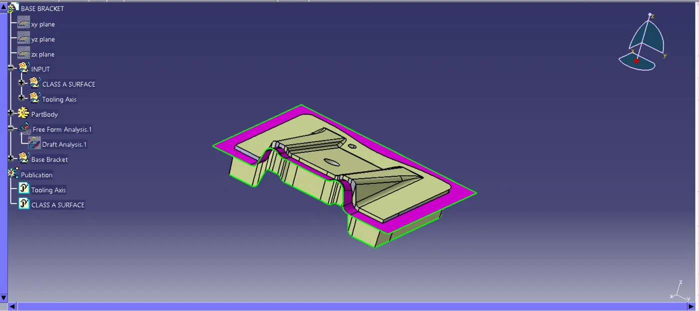
- The Final Base Bracket.
After Close Body Command:
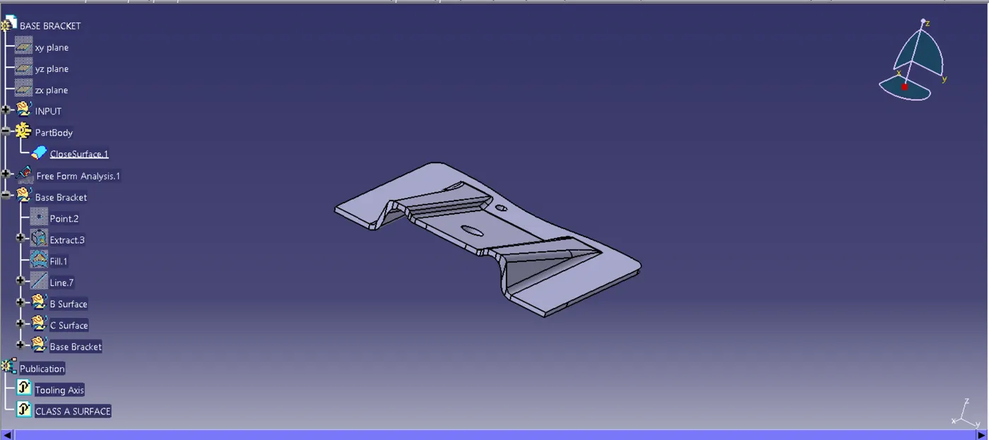
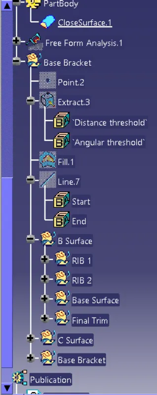
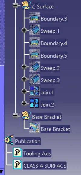
TREE DIAGRAM:
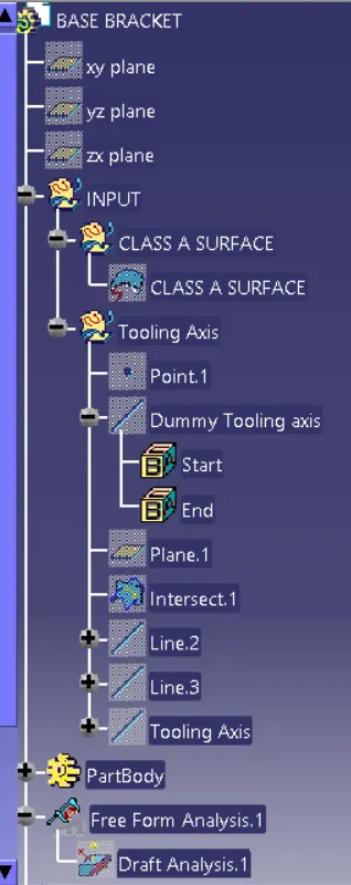
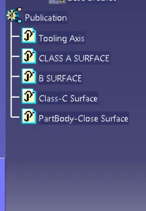
PUBLICATIONS:
CONCLUSION:
Hence. In this way, the Base Bracket Plastic component was created from the given Class-A surface.