Week 9 - Challenge 1 - Base Bracket Design
BASE BRACKET DESIGN
- Tooling Axis Creation in Catia:
Tooling axis creation is crucial for defining the direction in which the tool (mold, die, etc.) will move during manufacturing. Here's a step-by-step guide:
Access Workbench:
-Switch to the "Part Design" workbench in CATIA.
Create Reference Geometry:
-Create a point on the extracted base surface of the part then define the "Axis System" on that point(Point Should be in the middle of the base in order to achieve correct tooling axis).
-Choose the desired plane & project the surface on the plane then creates 2 lines on the projected sketch & then creates a bisecting line with the help of that extracted sketch.
-Repeate the above process on other plane, If there is not any opposite lines then define the angle to the line (more than 3degree).
Define Tooling Axis:
-In the "Generative Shape Design" workbench, create intersection line , use line command (using bisecting option) & create the bisecting line.
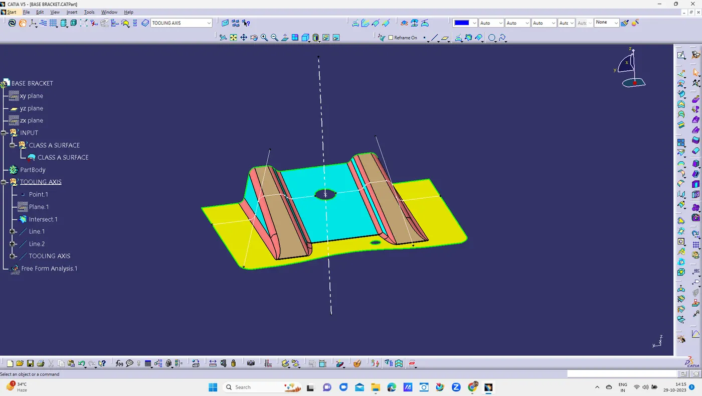
Draft Analysis in CATIA:
Draft analysis in CATIA involves evaluating the angles and directions of draft on a part. Draft is essential for mold design and manufacturing processes, as it allows for easy ejection of the part from the mold. Here are the key steps for draft analysis in CATIA:
Open the Part:
-Open the base bracket part in CATIA.
Activate Draft Analysis:
-Navigate to the "Analysis" workbench.
-Select the "Draft Analysis" tool.
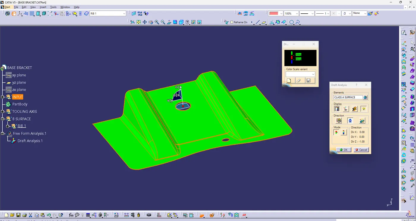
Set Parameters:
-Specify the draft analysis parameters, such as the draft angle and reference direction (Tooling Axis).
Review Draft Analysis Results:
-CATIA will highlight regions with insufficient or excess draft.
-Evaluate the draft angles to ensure they meet design and manufacturing requirements.
- CLOSE BODY DRAFT ANALYSIS :-
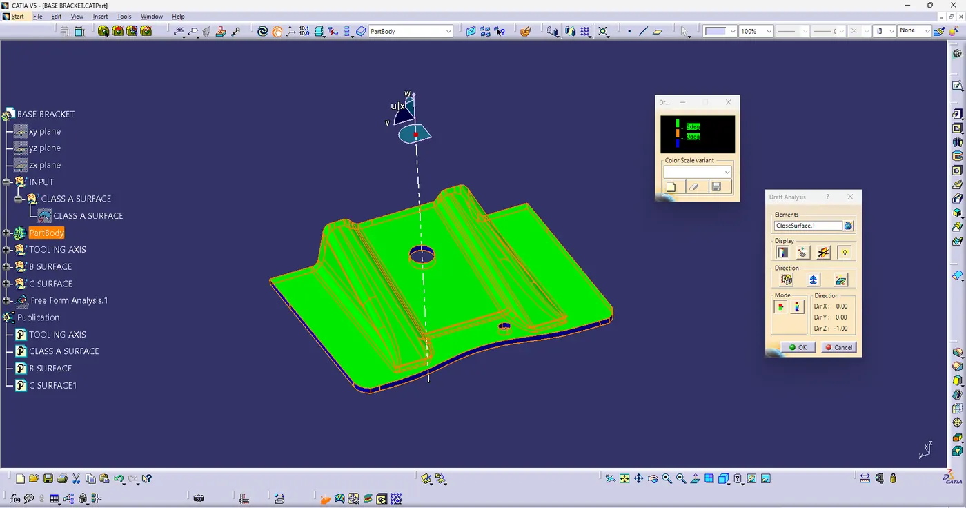
Make Adjustments:
-Modify the part geometry if necessary to achieve the desired draft angles.
Validate Changes:
-Re-run the draft analysis to confirm that the required draft has been achieved.
Specify Direction:
-Set the direction of the tooling axis using the appropriate commands.
- CLASS A SURFACE :-
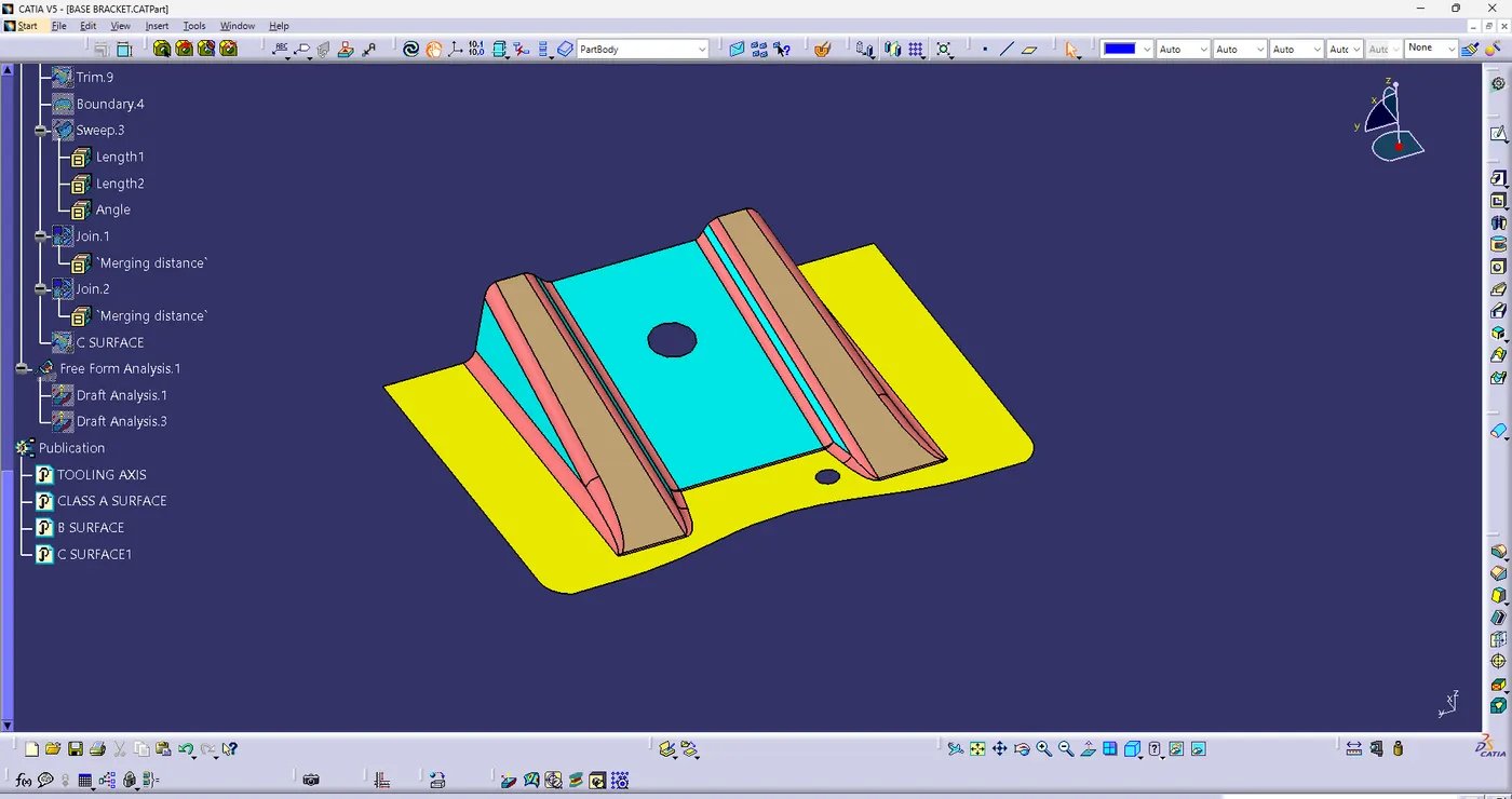
- B SURFACE :-
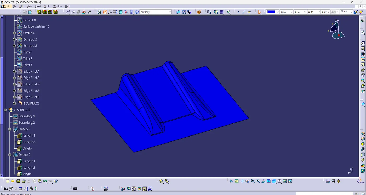
- C SURFACE :-
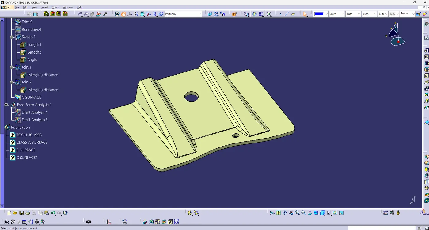
- CLOSE BODY SURFACE :-
IN THIS CHELLANGE WE WILL USE CLOSE SURFACE METHOD , 1ST WE WILL CREATE BODY WITH USE ALL SURFACE CAMMANDS THEN WE USE CLOSE SURACE COMMAND
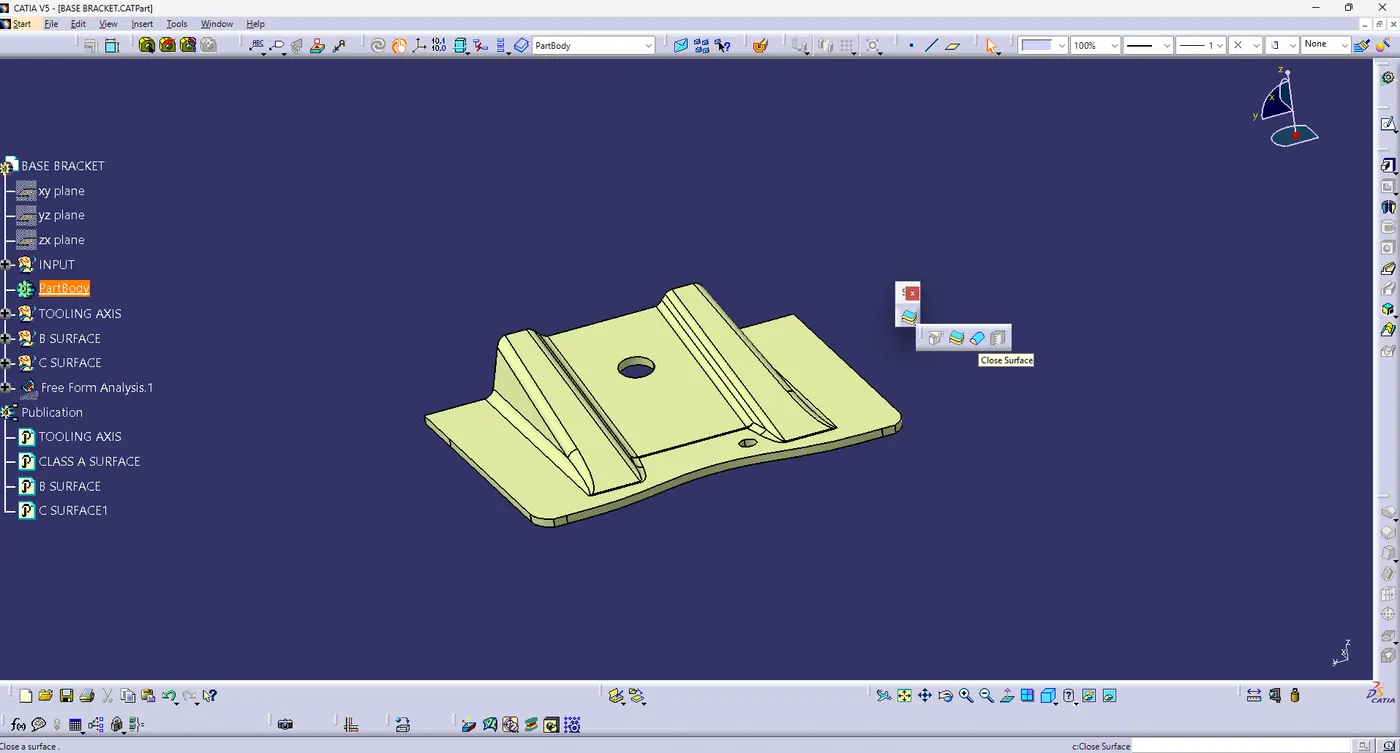
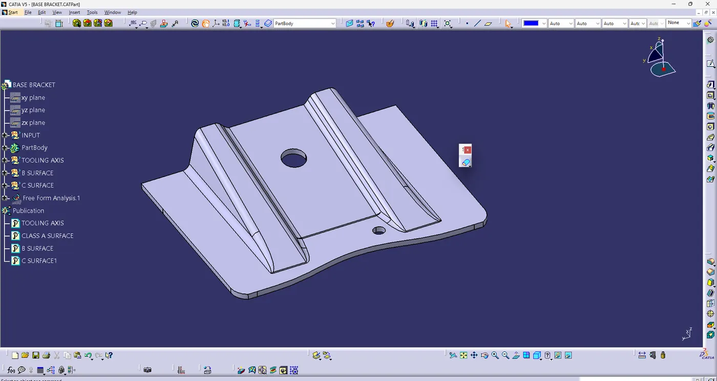
- ALL VIEWS :-
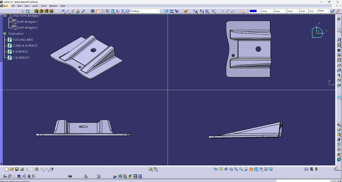
Final Validation:
-Validate the tooling axis by simulating the manufacturing process, ensuring it aligns with the design and draft requirements.