Week 9 - Challenge 1 - Base Bracket Design
Dear Evaluator,
This submission contains the following things:
a) Cad for Base Bracket as an attachment
b) The images as required
c) Report on the selection of the Tooling Axis
d) Report on Draft Analysis.
Report on Tooling Axis Selection
What is Tooling Axis?
The tooling axis is the line corresponding to the up & down movement of the Core and Cavity parts of the tool. Its selection plays an important role in the cost of tooling, manufacturing quality, and ultimately in the efficient mass production of the component.
How to determine the Tooling Axis?
The tooling axis could be either an X, Y, or Z axis of the component depending upon factors like Component Symmetry, Complexity of Design, avoiding the need for Side cores and Lifters, or keeping them to a minimum if unavoidable. The side cores and lifters add to the cost of tooling and also increase the production time, hence they have to be avoided.
Calculation of Tooling Axis by Bisection Method:
- Study the profile of the component closely along the X, Y & Z directions.
- Choose the most appropriate direction along which the component can be divided into 2 symmetric parts.
- Try and keep the elements like holes, ribs, protruding parts, etc. along the tooling axis so as to avoid side cores and lifters.
- Considering the above things assume a rough Tooling Axis.
- Now identify the crucial faces that may create a drafting problem (The faces that are parallel or almost parallel to the tooling axis).
- Extract their profiles and draw lines along them.
- If you have such symmetric lines on both sides of the Tooling Axis then draw their Bisectors.
- If you have followed the procedure correctly then these bisectors will coincide with the rough tooling axis. If that is the case, you can finalize that as the final tooling axis of the component.
- Please note that you may have different bisectors if your component has a complex design. In such a case, you must consider the line that fits most symmetrically on your component.
- It is the direction of the Tooling Axis and not its exact position that is important for tool designing.
Report on Draft Analysis
What is a Draft?
When a material is injected inside the Tool it tends to stick on the core edges upon shrinkage. The vertical faces of the components are the most susceptible to this problem. To avoid this a draft is given along them. Draft is an angle that the vertical faces of the component make with the Tooling Axis. It is given deliberately by the designer, in order to reduce the friction and the resulting wear& tear on the surface of the Component and tool. It minimizes the drag and eases the injection process thereby enhancing the component finish and increasing the tool life. The value of the draft can be 3 degrees or more depending upon the requirement. For precision parts like screw holes, it is 0.5 degrees.
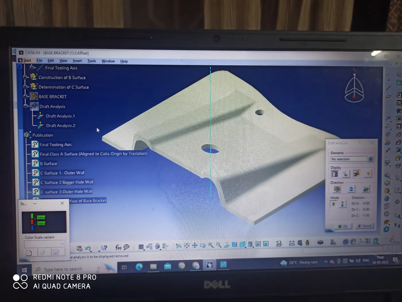
In industrial practices, the designers have to construct a solid model using Alias CLASS A Surface as input. Before proceeding with the solid model it is advisable for them to perform a Draft Analysis, which can be easily done using Catia's Draft Analysis tool. The Draft analysis tool can be located as follows:
Insert> Analysis>Feature Draft Analysis
How to perform Draft Analysis on a Class A Surface or a Solid part in Catia?
- Go to Insert > Analysis> Feature Draft Analysis.
- Customize the Tools by enabling the material option in the customization drop-down menu.
- Now bring the Drafting compass to the component origin and align the W direction of the drafting compass with the Z direction of the Tooling Axis.
- Once it is done, lock the compass in that position.
- Now select the Colour table from the display option of the drafting tool and specify the draft angle by double-clicking the green area.
- Now click anywhere on the component, the component faces that satisfy the draft angle will appear green and those not satisfying will appear red.
- There are many other features and tools inside the drafting tool like Running Point Draft Analysis.
- It enables you to check the draft angle anywhere in the component through a swipe of the mouse.
- If the Class a Surface satisfy passes the draft Analysis then you can proceed further with it.
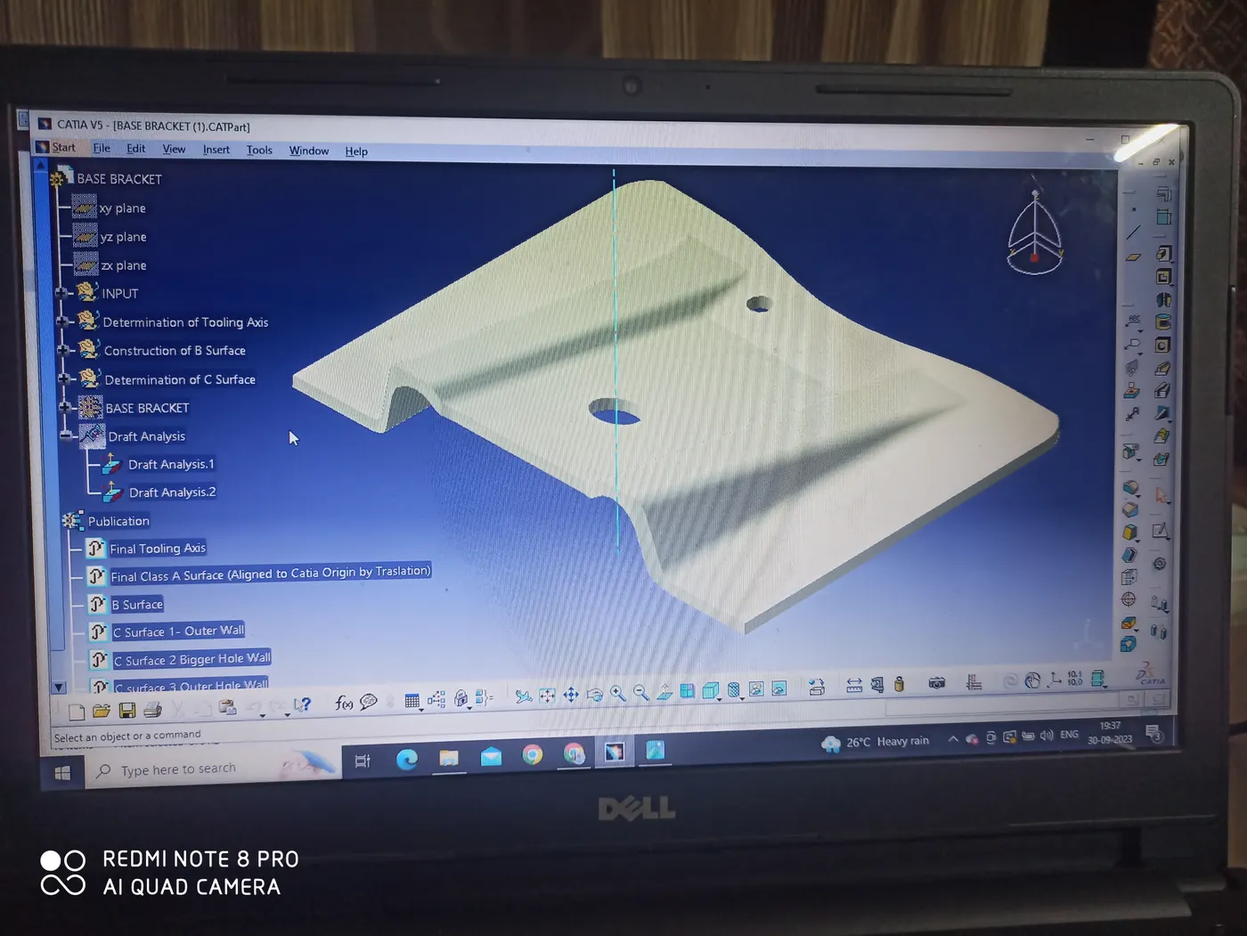
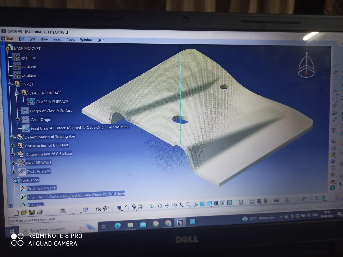
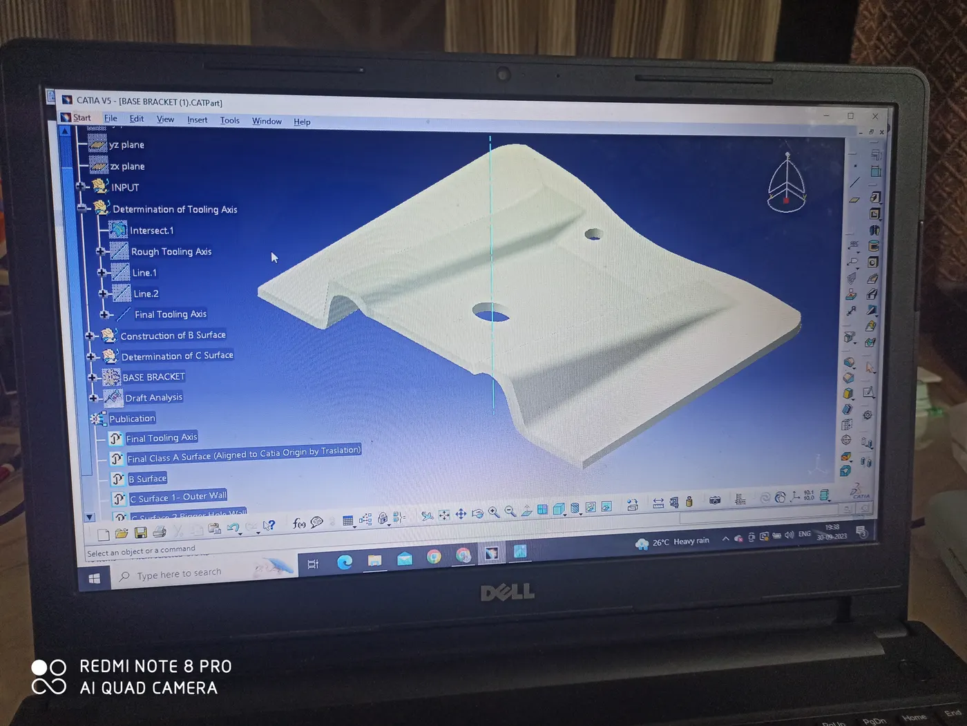
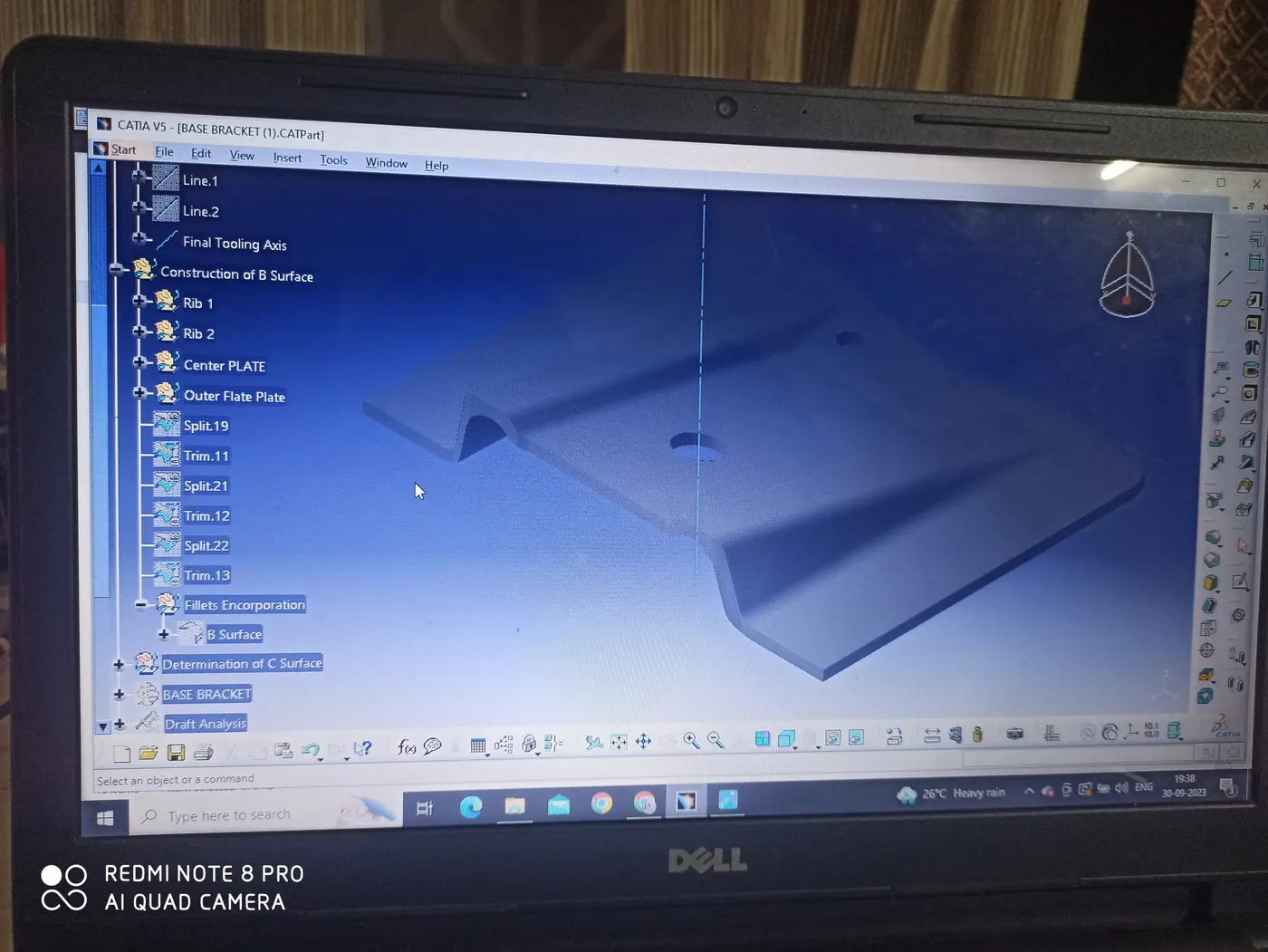
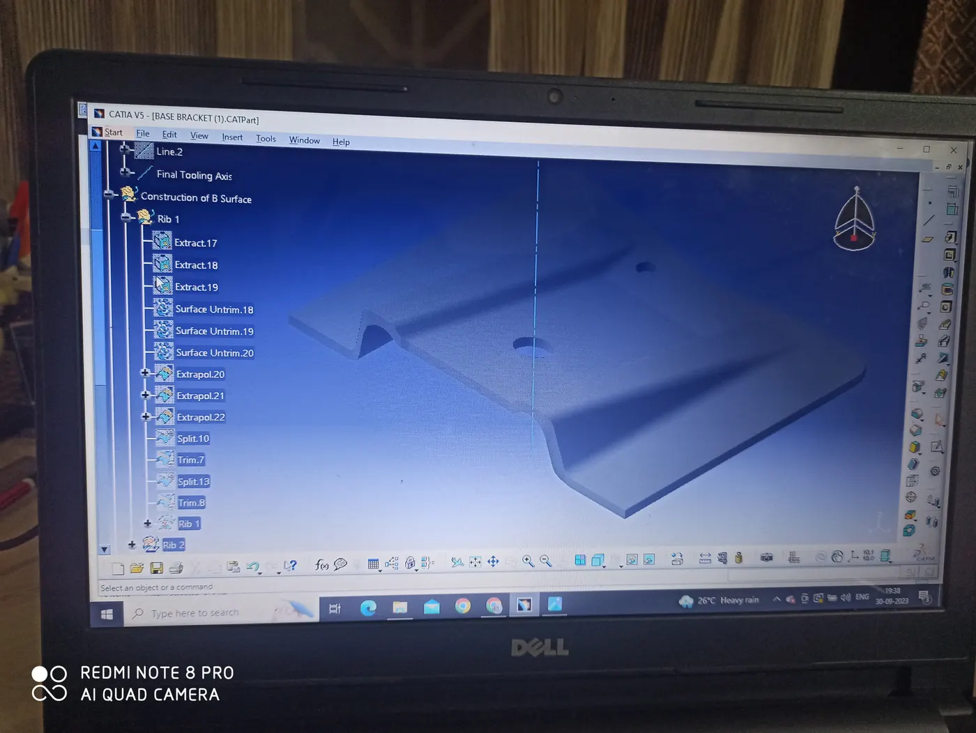
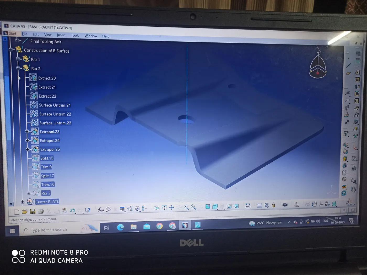
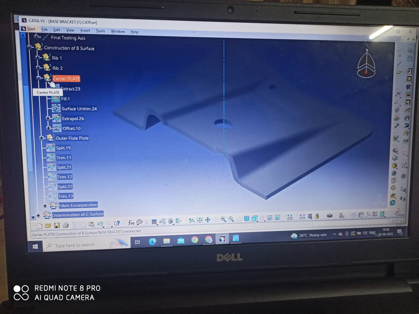
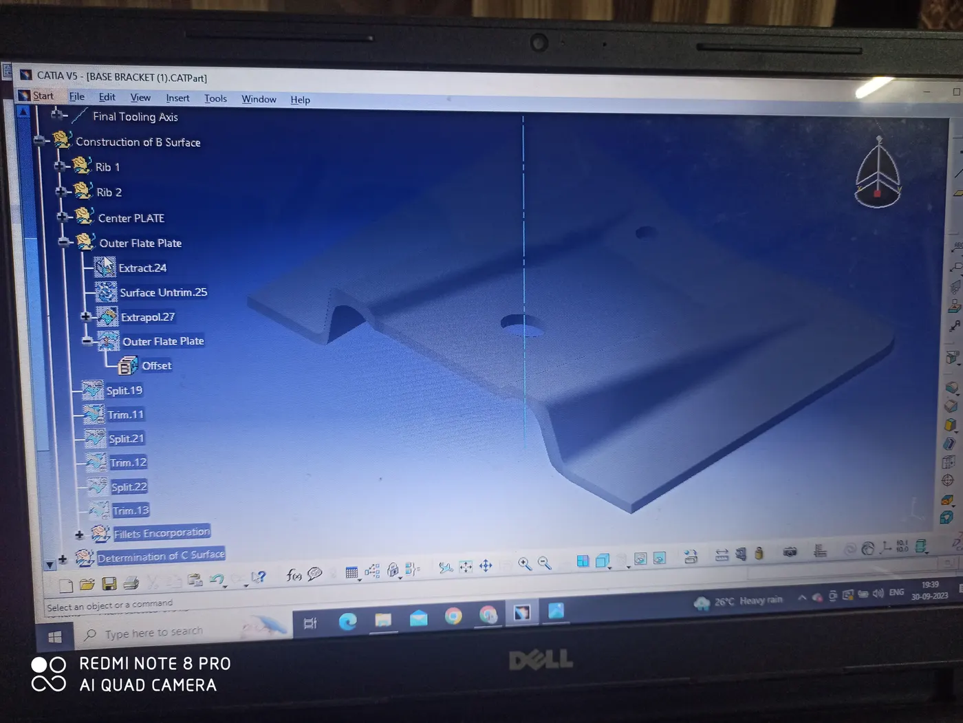
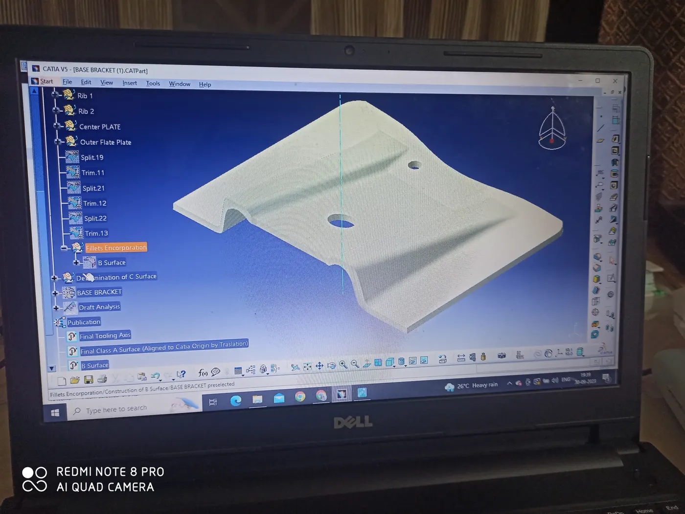
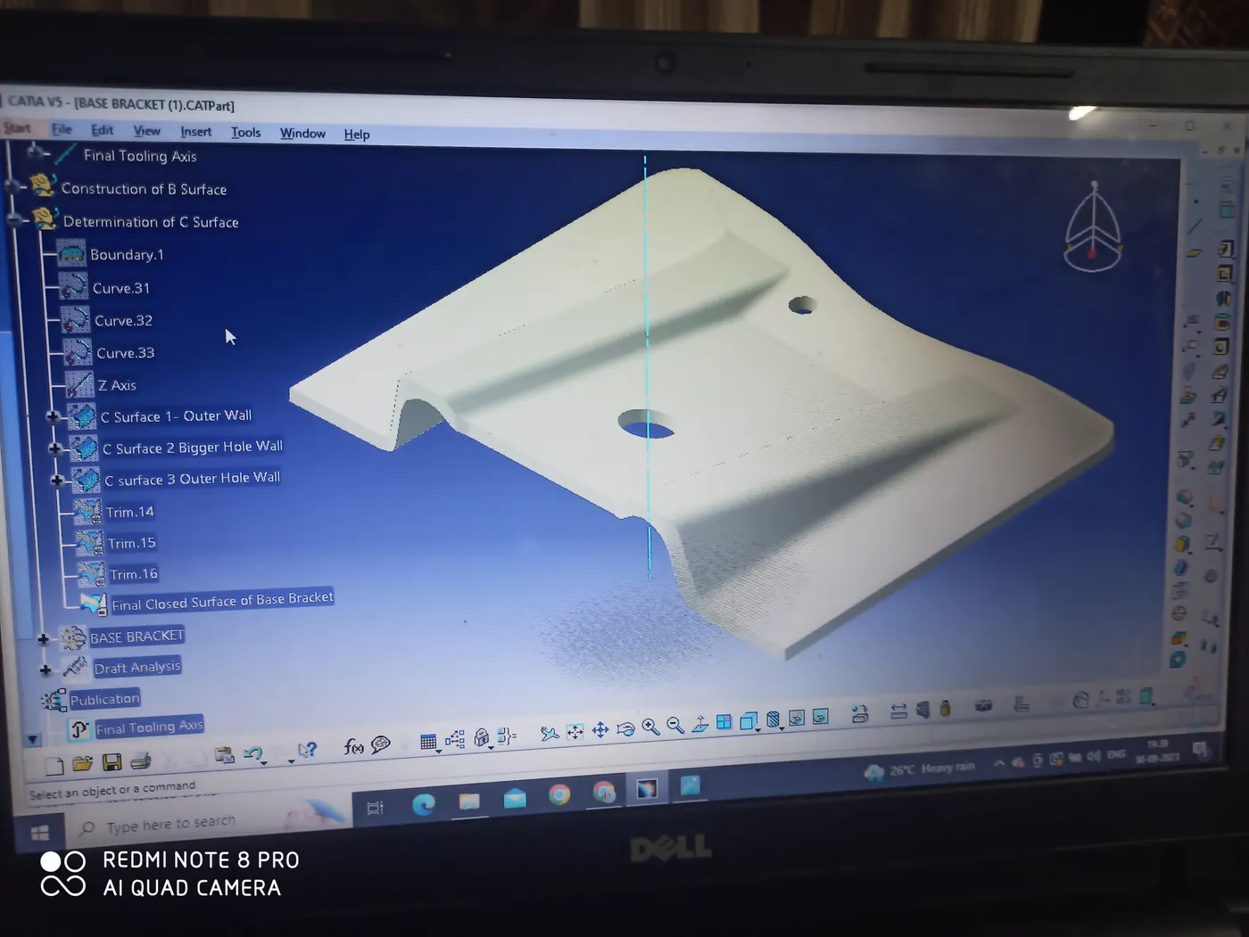
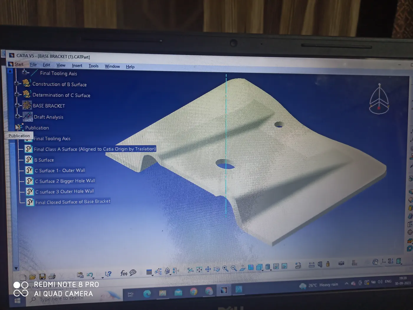
Images:
Thankyou.