Week 10 - Challenge 1- Attachment Feature Creation (Ribs & Screw Boss)
Design Report for the creation of Door Handle, its Ribs & Screw Bosses
The model for Door Handle has been created here using the Class A Surface as input.
The procedure followed has been summarised in this report.
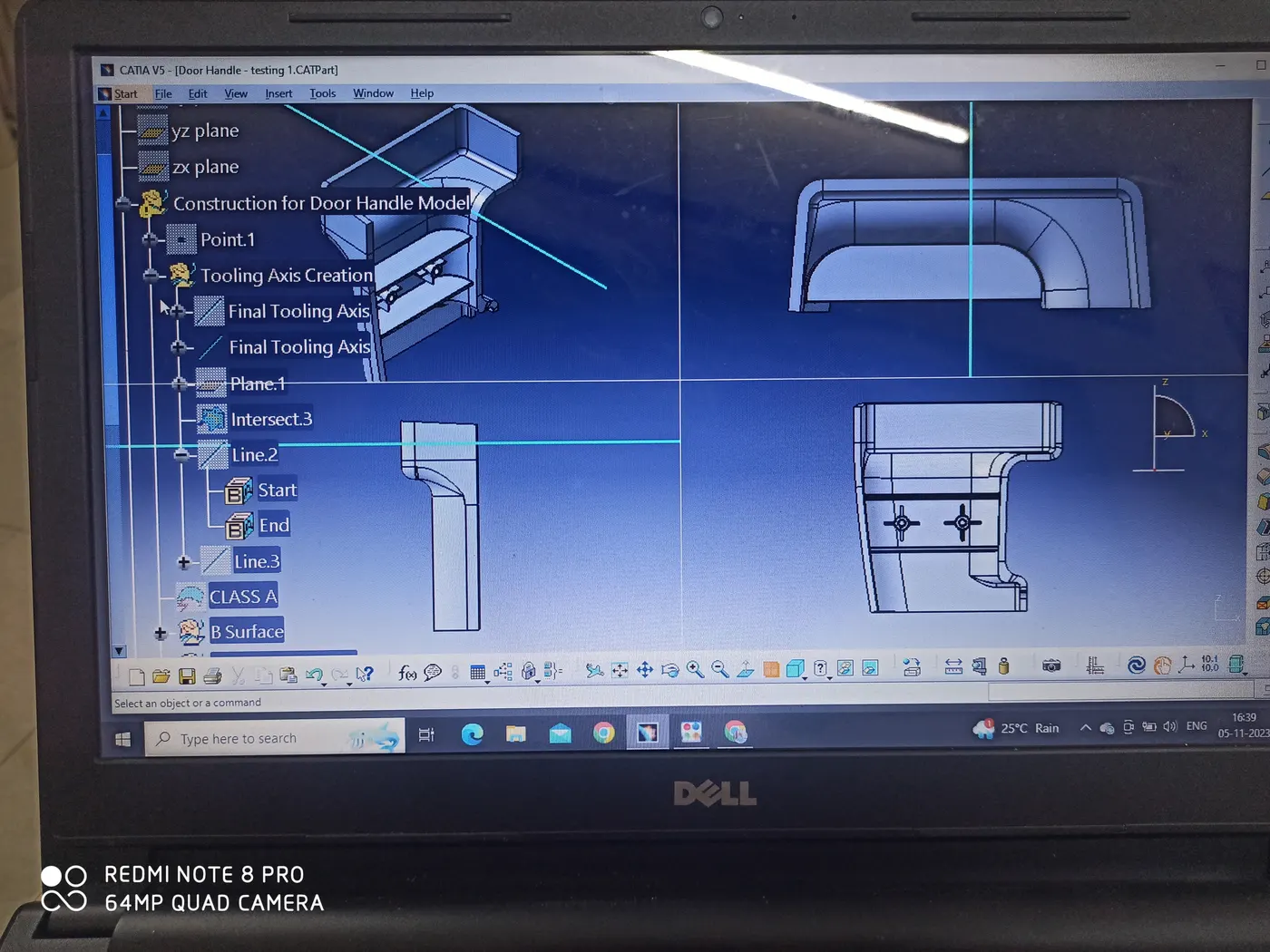
a)Step 1: Creation of Tooling Axis
The symmetry of the Drill Handle was examined along all xy,yz & zx planes and it was found that the y-axis is most suitable for Tooling. Assuming the y-axis as the Dummy Tooling axis a Draft Analysis was carried out considering a 3-degree draft to the tooling axis and it was found that the entire Class A surface of the Door Handle can be cleared positively. Hence the Y-Axis is taken as the correct Tooling Direction for the component.
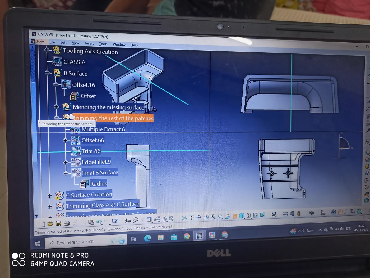
Step2: Creation of B Surface:
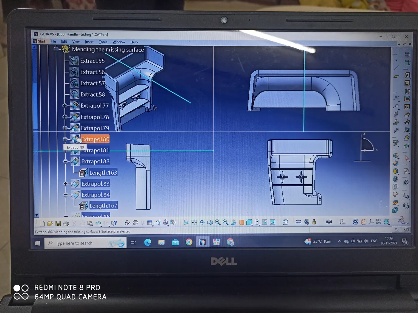
Here the Direct Offset Method has been adopted for the creation of B Surface. The entire Class A surface has been offset inwards with a distance equal to the thickness of the component, i.e. 3mm. We notice that the majority of the Class A surface gets offset correctly, leaving one major problem area which is a fillet patch in one of the corners. It has been addressed and corrected by manually extracting and producing the surfaces forming the corresponding fillet. The corner is then filleted manually, taking reference from the fillet values in the Class A Surface and subtracting the component thickness from them. After mending the missing fillet patch in this way, the offset surfaces have been extracted and trimmed to it. This resulted in a smooth gap-free B Surface that can be used further for creating the close surface body for the component.
Step 3: Creation of C Surfaces
Even though the component has a complicated Class A surface involving many twists and bends, the C surface profile is simple. If we closely observe the boundary profile of the Class A surface, we notice that the component has 2 two opposite edges that would result in C surfaces parallel to the tooling axis. We need to provide an outwards draft of 3 degrees, while the rest of the C surfaces will be perpendicular to their respective Class A parents. The C Surfaces have been divided into seven patches which are created with Sweep 2,3,5,7,8,11 & 12. These patches are extrapolated by the minimal amount to intersect with each other and trimmed to form a single C Surface. Kindly refer to the tree structure in the model to understand the details.
.
Step 4: Trimming Class A & C Surface
The Final C Surface is trimmed with the Class A Surface and we get a single output of Class A and C Surface that ca be trimmed to the B surface to achieve the required Close Surface Body for the Drill Handle.
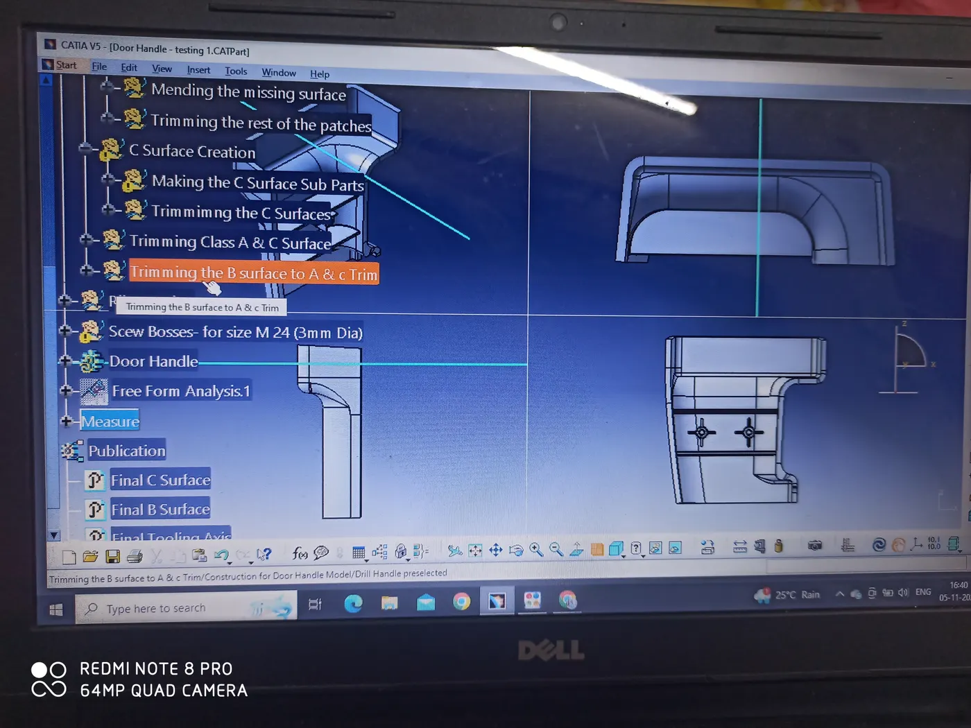
Step 5: Trimming the joined Class A & C Surfaces to the B Surface.
This is the last step in the creation of the closed Surface of the Drill Handle component. An intersection of B Surface with the previous output has been taken to check whether they were meeting perfectly throughout the boundary of the component. We found a connexity error at one spot on the B Surface. To remove that C Surface was extrapolated by a minimal amount in the B surface Direction. The extra portion of B Surface was the split and trimmed with the A & C Surface trim ultimately.
Step 5: Creation of Solid Body out of the Close Surface Body
We switch to the part design workbench and use the create solid out of closed surface body command to have the final model for the Drill Handle.
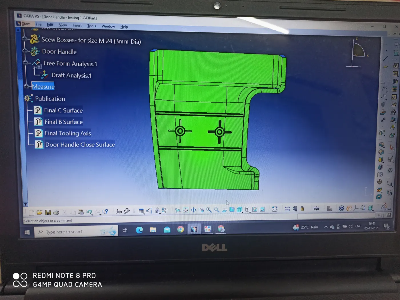
Step 6: Draft analysis of the final Solid
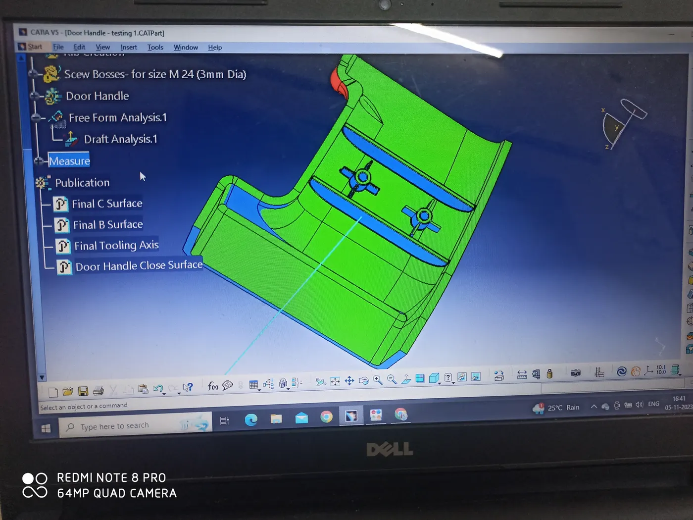
Next, we carry out the draft analysis of the final component and check whether all the surfaces are falling on the positive farm or not. Here the Drill Handle model meets all the requirements of the draft at all the surfaces which is indicated by the green colour in the draft analysis report. Hence the model is correct and approves of all the standards.
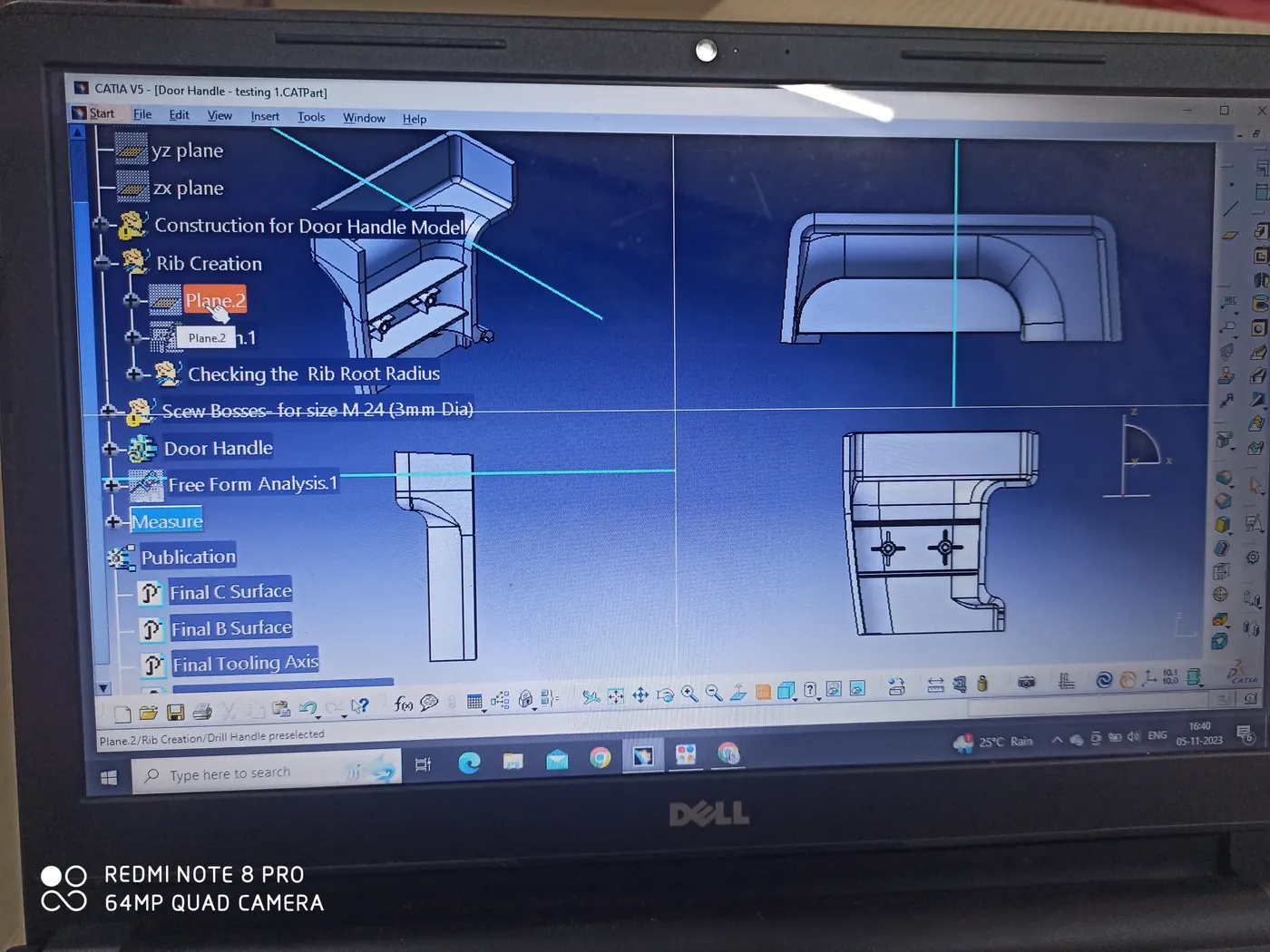
Creation of Ribs
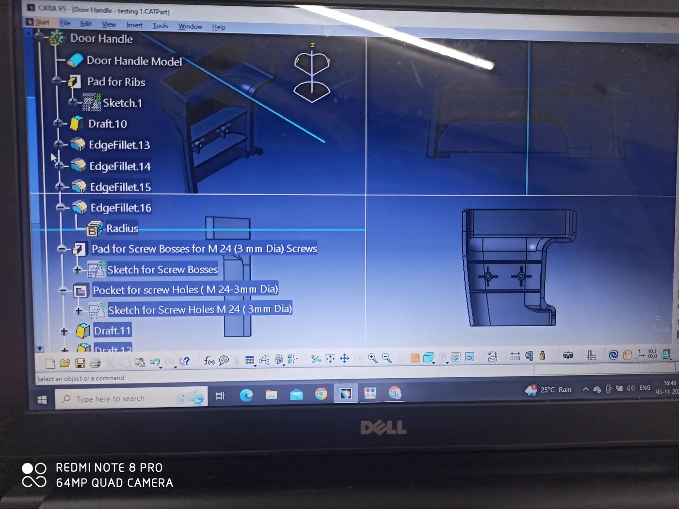
The thickness of the Drill Handle is taken to be 3 mm here and according to the rib design rules, the model requires a total of 4 ribs with a height of 15mm, and a thickness of 1.5mm. But we also have to provide 2nos of Screw bosses here. So the center 2 ribs have been omitted to accommodate them subsequently The screw bosses have their own respective ribs. Hence doing so, will not hamper the net strength of the component.
Rib Specifications:
Toral Nos: 2
Height: 15mm
Thickness: 1.5 mm
Fillet: 0.25 mm
Draft: 0.5 degree
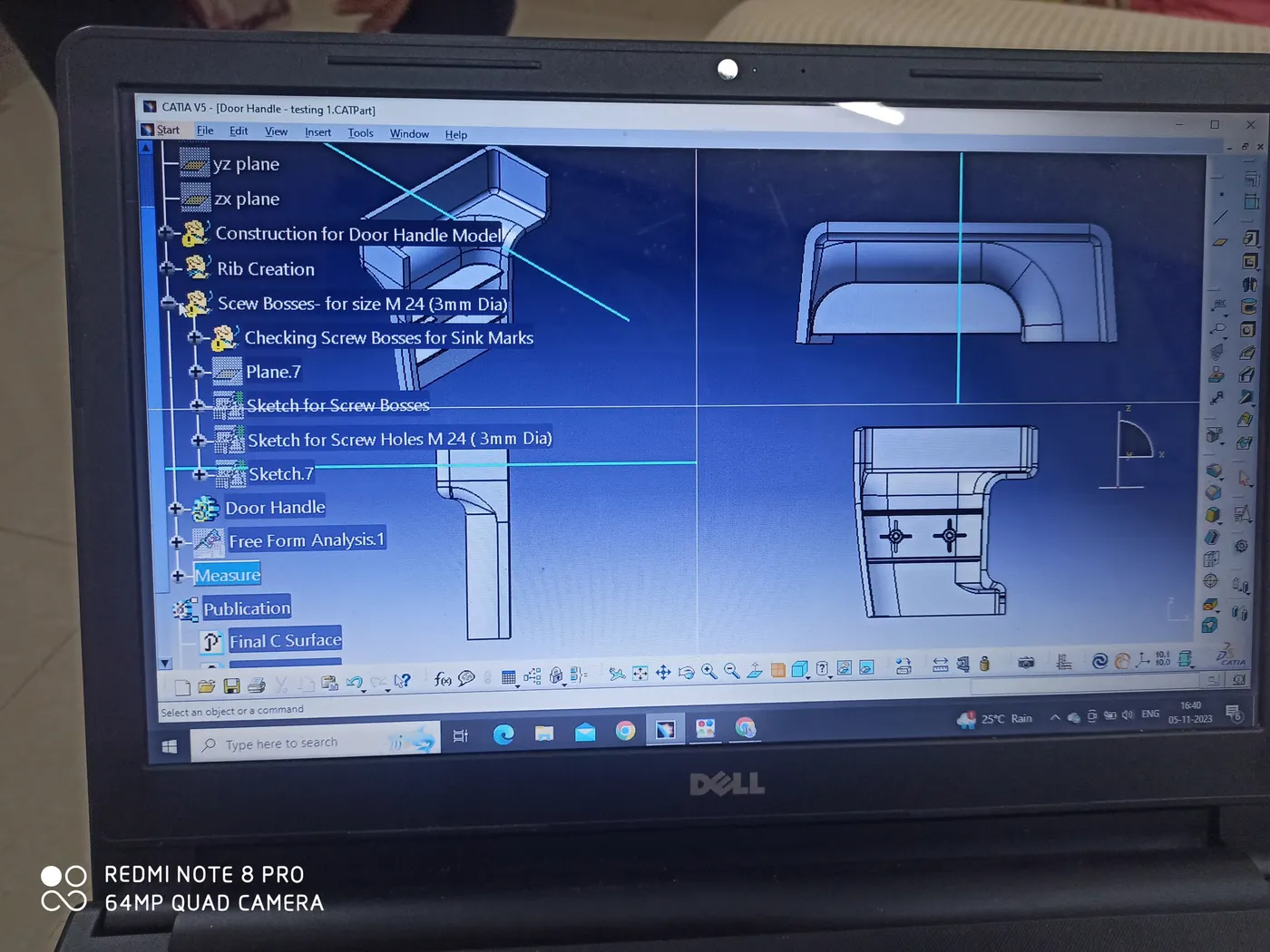
Creation of Screw Bosses.
The component has been provided with 2 Screw Bosses considering to house one screw each of M 24 (3mm Dia ) Screws. They have been provided with 4 ribs for support.
Screw Boss Specifications:
Total Nos:2
Height: 9 mm
Internal Dia: 3mm
External Dia: 6mm
Wall thickness:
Draft: 0.5 degree
Fillet: 0.25mm
Additional Ribs: 4 each
Please refer to the Model for explicit details. The Photos of the model in various views and the required color coding for Draft Analysis have been attached for 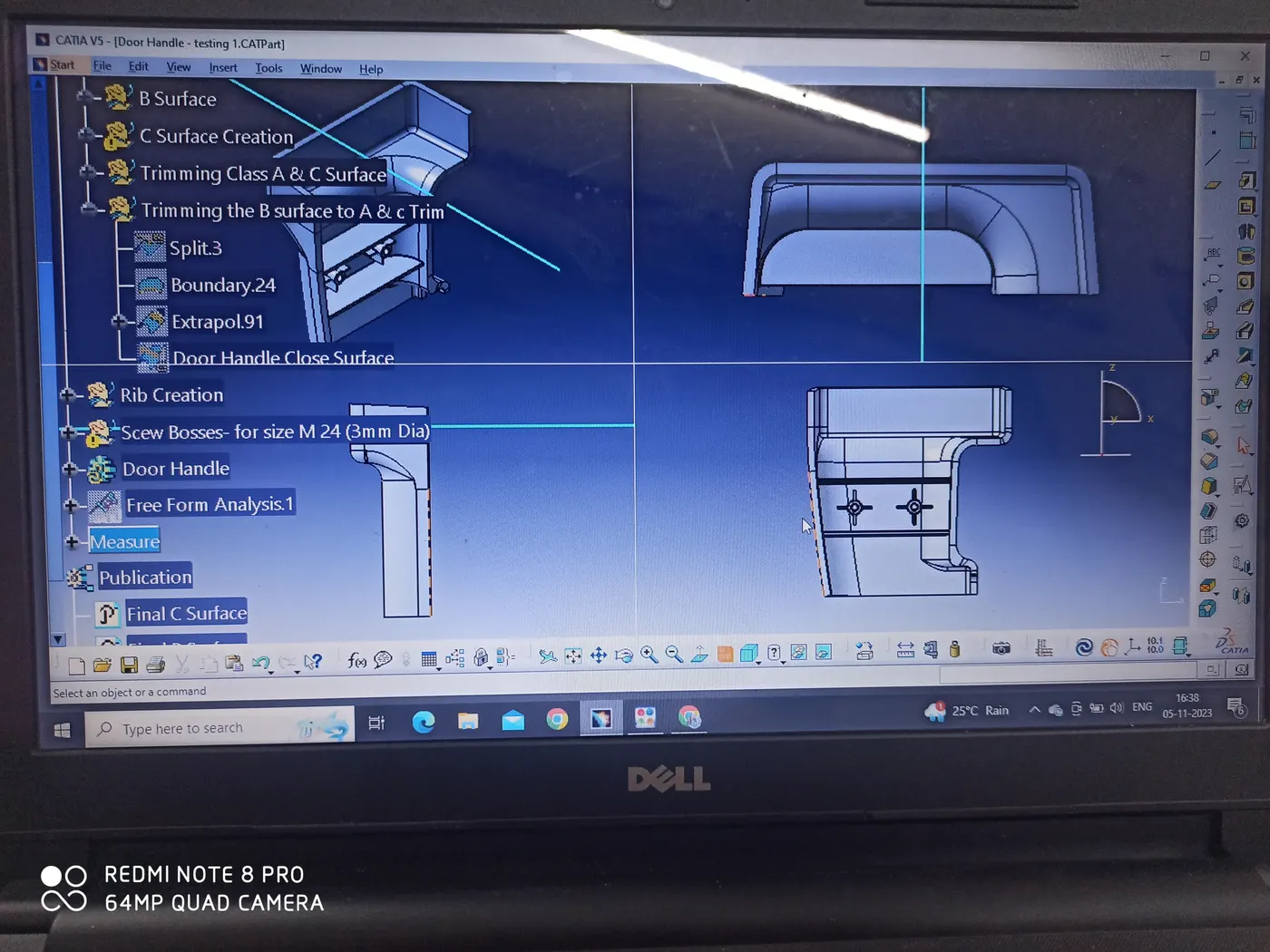
better clarity.