Week 10 - Challenge 2- Attachment Feature Creation (Dog House)
Design Report for Week 10 - Challenge 2- Attachment Feature-Dog House
Tasks to be done:
-
Creation of a Solid Model for Door Trim
-
Creation of Dog House Feature based on guidelines mentioned in the tutorial.
Inputs:
-
Class A Surface
-
The component thickness is 2.5 mm.
c) Positioning of Dog Houses not mentioned precisely (hence assumed as suited)
Design Steps involved
A) Creation of a Solid Model for Door Trim
-
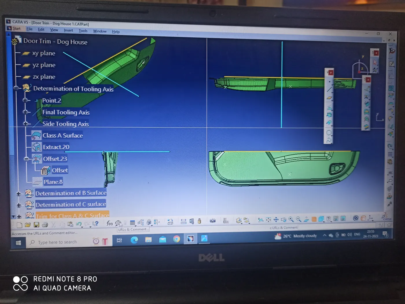
Creation of Tooling Axis
This is a model that involves a dog house feature, that requires a side core for achieving the design. Hence there will be 2 tooling axes-
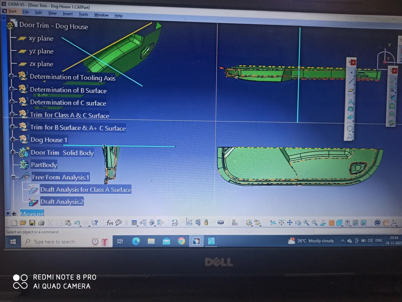
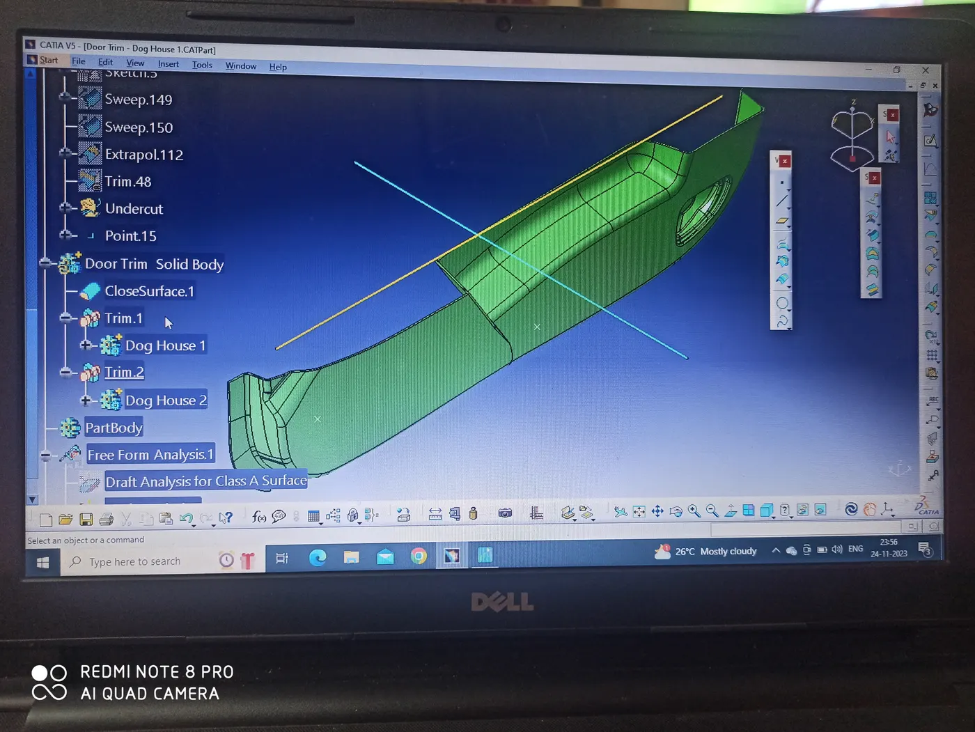
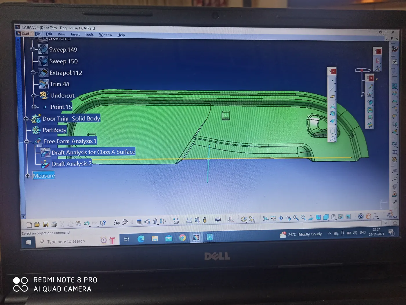
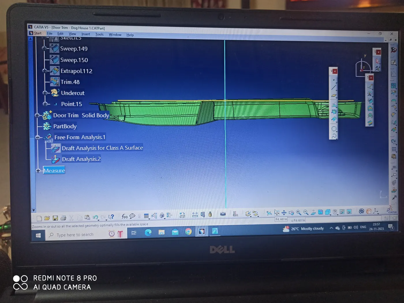
i) ‘Vertical Tooling Axis’ corresponds to the tooling direction for the Door trim model and external walls of the Dog House Feature. In this case, it's the Y axis, and it satisfies the draft requirement of 3 degrees. The draft analysis for the Class A surface confirms its accuracy.
ii) ‘Horizontal Tooling Axis’ corresponds to the tooling direction of the side core that will create the internal surfaces of the Dog House feature. In this case, it's the X-axis and it satisfies the draft requirement of 1.5 degrees. Draft analysis for Dog House core confirms its accuracy.
-
Creation of B Surface
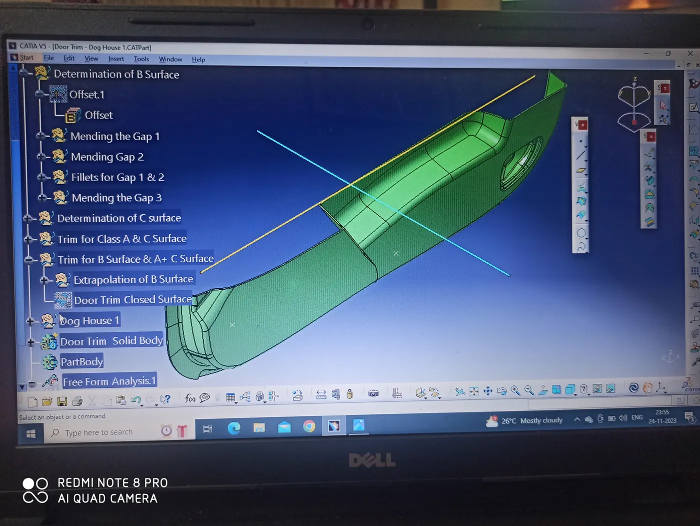
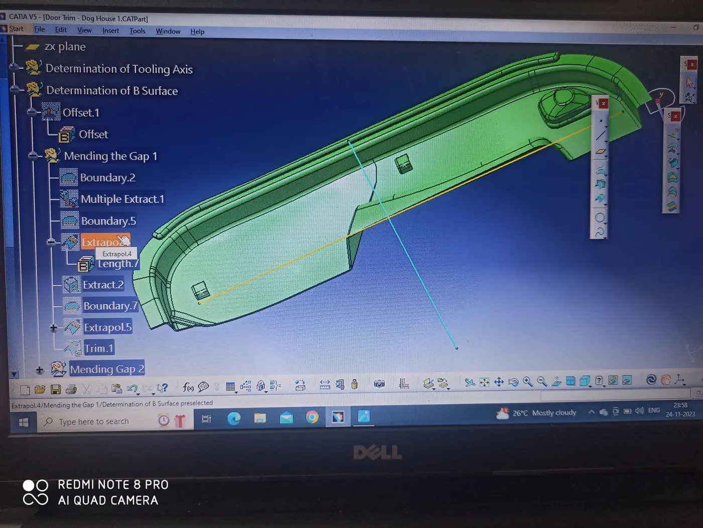
The direct offset method is used here. The given Class A Surface has been offset upwards by an amount of 2.5 mm, corresponding to the thickness of the component.
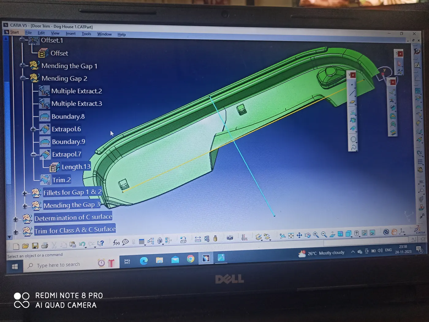
However, upon offsetting, gaps at 3 locations were generated. They have been attended one by one and can be seen in the 3 geometrical sets named ‘Mending the Gap 1, 2 & 3’ respectively. The missing fillets were given, taking the dimensions from the class A Surface, adding & subtracting the component thickness according to the surface profile & curvature.
-
Creation of C Surface
Looking at the surface profile, the C surface along the entire boundary is given a draft of 3 degrees with respect to the Vertical tooling Axis. To achieve the required profile the C surface has been divided into 4 parts:
i) C Surface 1- Sweep command with 3-degree draft w.r.t the Vertical Tooling Axis
ii) C Surface 2- Sweep command with 3-degree draft w.r.t the Vertical Tooling Axis
ii) C Surface 3-Sweep command with 3-degree draft w.r.t the Vertical Tooling Axis
iv) C Surface 4- Sweep with reference surface command, with the ending edge of C Surface 3 as the guide curve and the balance Boubdary of the Class A surface, as the running profile.
The C surfaces were trimmed/joined together in succession and a single C Surface output is obtained. The respective geometric sets can be referred to for the details of surface creation.
-
Trimming of Class A & C surface.
The given Class A Surface & the C Surface obtained in the above step were trimmed together to obtain an A+C Surface. Refer to the respective geometric sets for details.
-
Trimming of (A+C) Surface with B Surface.
The A+C Surface is trimmed with the B surface obtained in the earlier steps and a close Surface body for the Door Trim is Created. Refer to the respective geometric sets for details.
-
Creation of a Solid Model for the Door Trim.
By switching to Part Workbench and using the Close Surface Command a solid Model for Door trim is obtained. Draft analysis is carried out for the door trim model and it satisfies the draft requirement. Refer to the draft analysis for the Door Trim solid model for the details.
B) Creation of Dog House Feature
-
The precise location of the Dog Houses is not mentioned in the inputs. So they have been assumed to take reference to the picture given in the inputs.
-
Drawing the Sketch for the Dog House Skeleton- The sketch is drawn on a plane that corresponds to the base of the Dog House. For this, a plane perpendicular to the Vrrtical tooling axis is inserted at the level of the component B surface.
Reason: Sketch drawn on the component b surface was resulting in an improper sweep. To facilitate the manufacturing, and achieving the required draft (1.5 degrees) the dog house should originate from a plane that is catly perpendicular to the vertical Tooling Axis.
-
The wall surfaces of the Dog House are obtained by sweep with draft direction command.
-
The top surface is obtained by close surface command, and that's how the Dog House Skeleton was obtained.
-
This skeleton has been thickened by 2 mm and a solid body was generated.
-
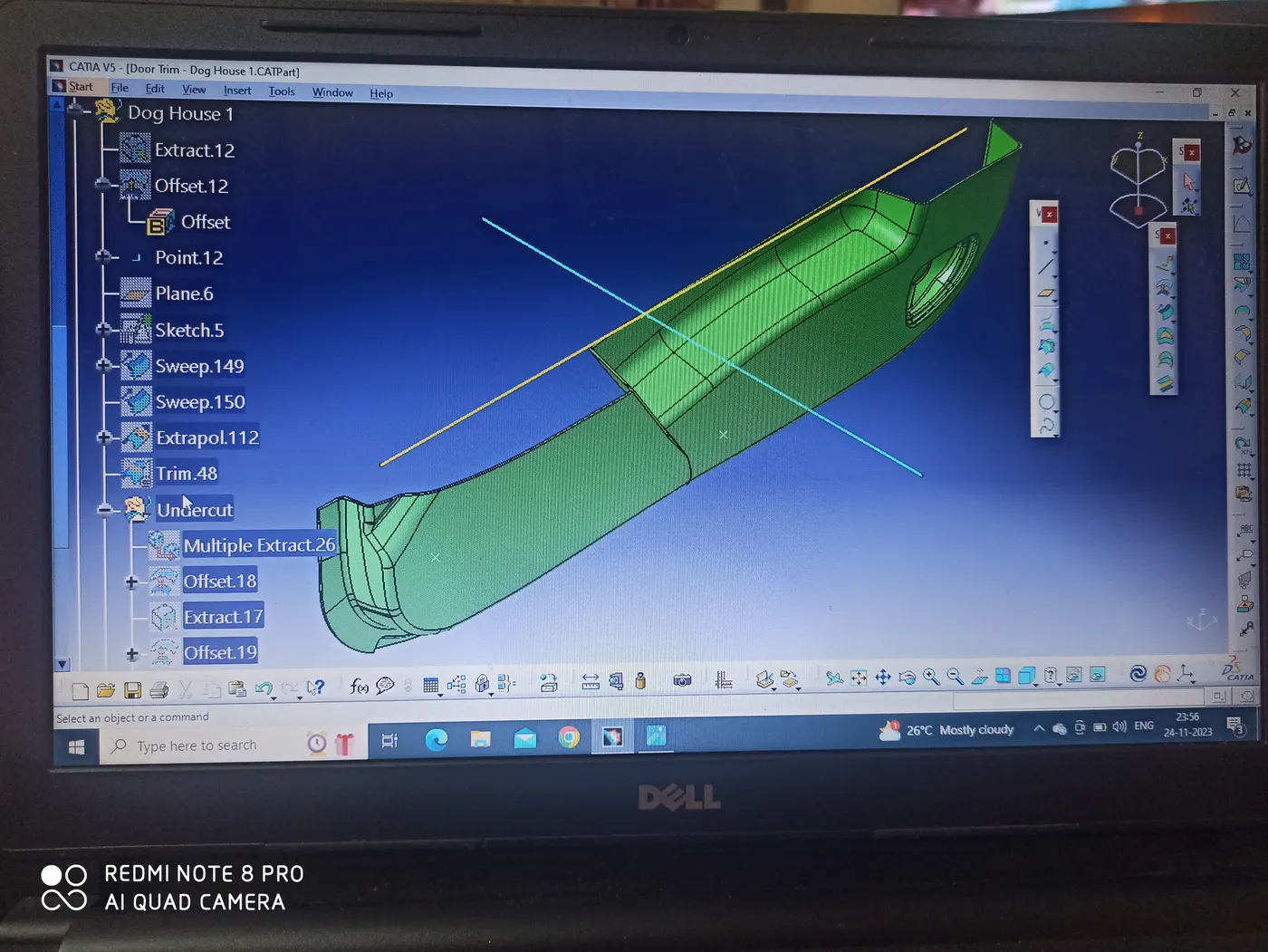
To make the undercut with the required C & B dimensions, another skeleton surface body was made. It was done by offsetting the dog house walls by the required values.
-
The Dog House body was then split by the undercut skeleton.
-
The inner faces of the dog house were drafted considering an angle of 1.5 with respect to the Horizontal Tooling Axis.
-
The outer edges were given a fillet value of 3 mm and the inner ones 1 mm.
-
That's how the Dog House model was completed and named Dog House 1.
-
The same model was copied and 'special pasted' on the second location and named the Dog House 2.
C) Trimming the Dog Houses to the Door trim Model.
The Dog House 1 & 2 were union trimmed with the Door Trim Model in sequence and that's how the challenge was completed.
Please refer to the Model and corresponding Geometrical Sets for details.
The images elaborating on the above explanation are attached below.