Week 9 - Challenge 1 - Base Bracket Design
CHALLENGE-1 (BASE BRACKET DESIGN)
AIM:
Create the base bracket use of given class-A-surface. Following the given guid line in challenge-1. Want to creat tooling axis, class-B-surface, class-C-surface and final step Draft analysis...
CLASS-A-SURFACE:
# The class-A-surface ensure that is no gap between the component using join tool. And check once to conform use boundary tool.
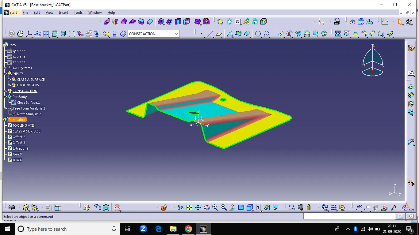
TOOLING AXIS:
# Creat intersect on class A surface. And creat point to point lines in both side and creat center point take the reference and creat biseting line that biseting line is consider as tooling axis.
CLASS-B-SURFACE:
# Select the surfaces in class A surface and untrim the surfaces.use of extrapolate tool and trim the connecting surfaces. And all reference surface are offset 2.5mm in downward in Z axis.
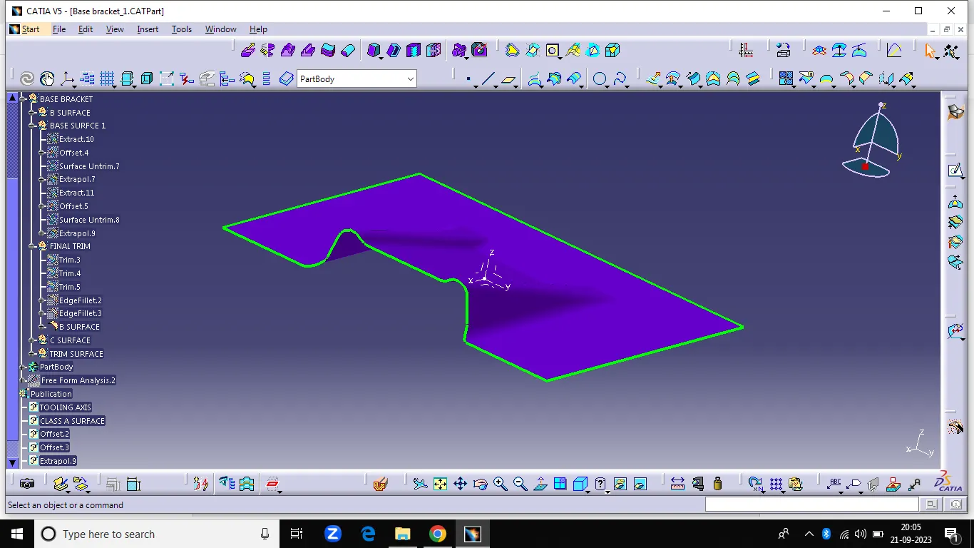
CLASS-C-SURFACE:
# Take the boundary of class A surface. And use sweep tool and give input of class A surface boundary and tooling axis is a sweep direction and given angle is 3deg.
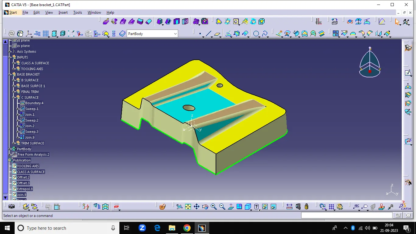
# Use the join tool to merge the class A surface and class C surface.
FINAL TRIM SURFACE:
# Un hide the class A,B and C Surfaces. and use the trim tool trim all unwanted surfaces.
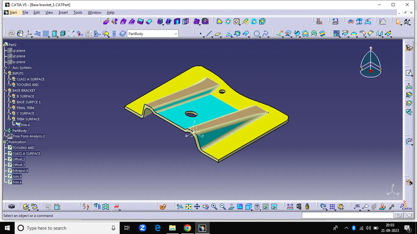
close surface:
# Convert surface design to part design. By useing of close surface tool select the final trim. To convert part design.
DRAFT ANALYSIS:
# Final step is draft analysis. Select draft analysis tool from the tool from the toolbar or go to insert > analysis > feature draft analysis tool. And select the compass and fit in to tooling axis .
# Lock the compass with tooling axis. And select direction tool it take reference is tooling axis and select the close surface part design. it will show error or given input is currect . Currect means its will show in green and blue colour.
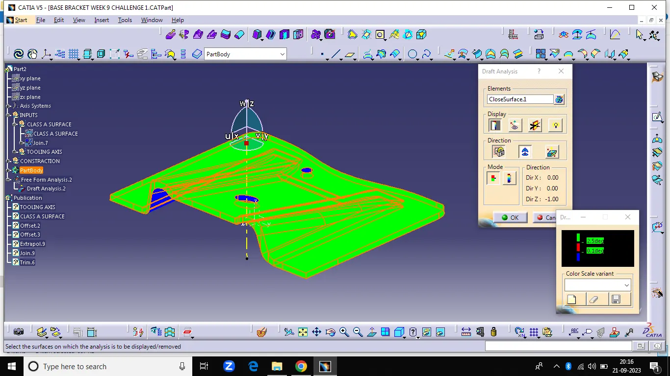
# The draft analysis helps ensure that the part can be easily released from molds during the manufacturing process. This process is very helpful to avoid error in the final product.