Week 9 - Challenge 1 - Base Bracket Design
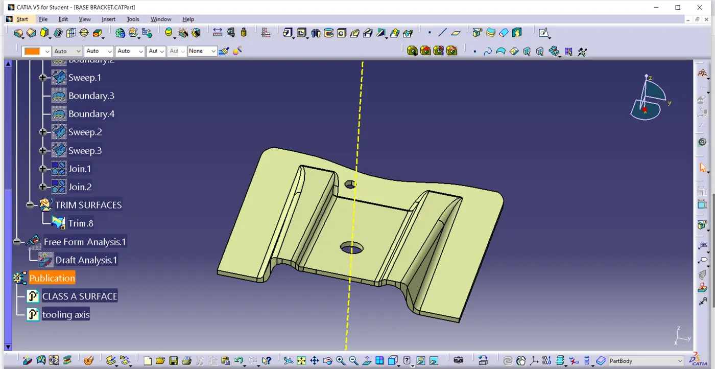
Aim :- To Create the Base Bracket Plastic component through the given Class-A surface. To begin with, the tooling axis for the given Class-A Surface should be created meeting the requirements of the draft angle and at the end perform the Draft analysis on the model.
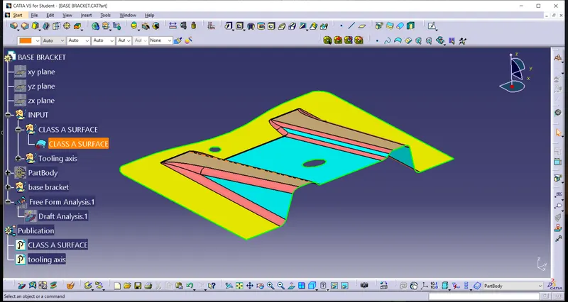
Class A surface :-
DESIGN CONSIDERATION:-
Class – A surface should be aesthetically smooth and good.Class – B surface should have all the supporting features like ribs.Parting Line should coincide with the B surface since flashing couldn’t affect the aesthetic of Class – A.Class – C surface should also pass the draft analysis.
PROCEDURE TO CREATING CLASS A SURFACE:-
First, the given styling surface is checked for any irregularities, and if found then it is corrected by using Trim, Extrapolate, Split, and Join commands.The Class A surface has some irregularities shown in the below figure. So join operation was performed on the surface and it became a clean surface.The below image shows that the Class – Surface is clean and no irregularities are present, so let's move on to the next step.
Creating a tooling axis in class A surface:-
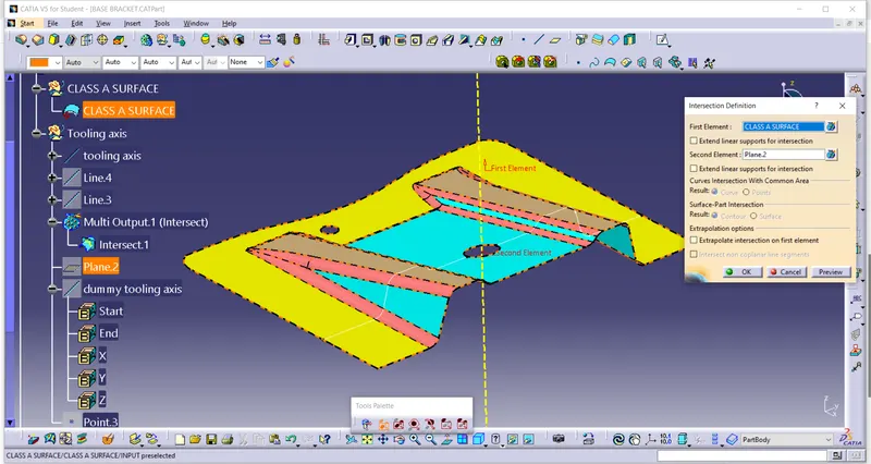
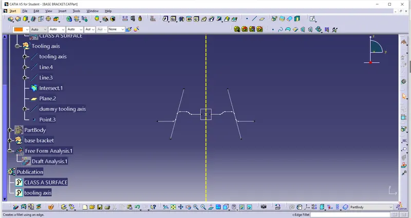
The direction in which the mould open and closes is the tooling axis.Check the connectivity of the surface and ensure there will be no gap between the surfaces and then define the tooling axis.While creating a tooling axis give the tooling axis on a flat length surface or the surface which have a hole on it.Create a point on the surface where we are going to create the dummy tooling axis and using line command crate an axis. If there is a circle or flat length surface which is recommended.
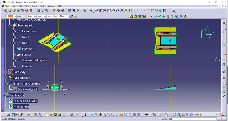
Create a class B surface:-
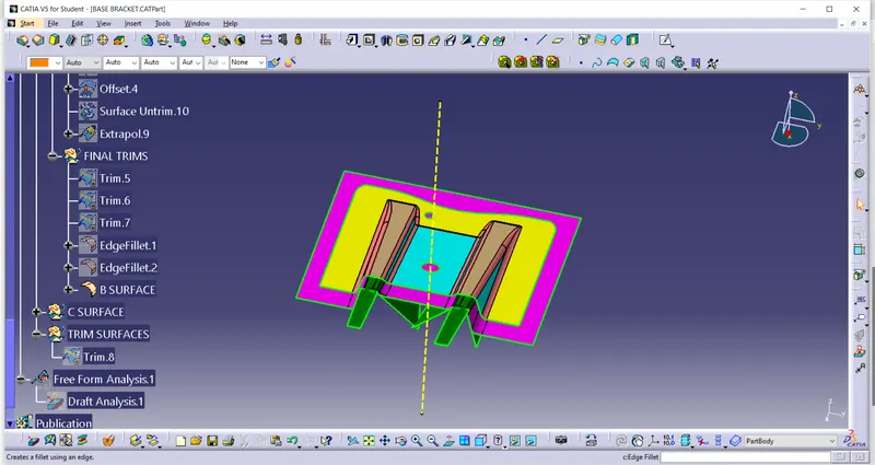
Class B surfaces are the secondary surfaces in plastic component design.In this model Class B-Surface is extracted from the A-surface and it is offseted at 2.5mm in downward direction.To create the class B surface, I considered the entire surface has 3 parts 'Rib-1, Rib-2, and Base surface.
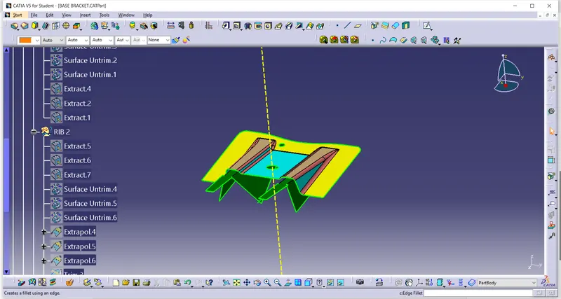
Create a class C surface:-
Class C is often specified for interior surfaces not readily visible, surfaces that will be covered by another part when assembled, or surfaces which the Customer feels do not need to meet a high cosmetic finish.C-Surface connects the class A-Surface and B-Surface. It is created using Sweep command. Boundry of the class A-Surface is swept along the tooling direction.
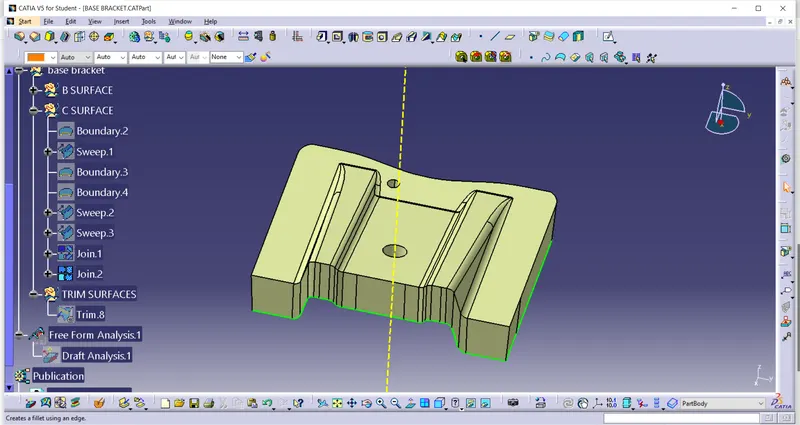
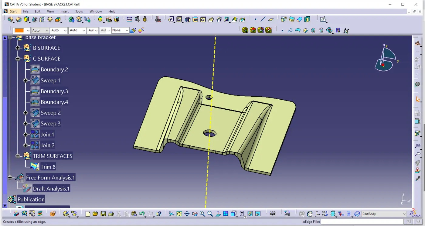
Trim Surface :-
Draft Analysis:
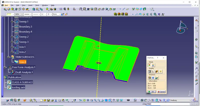
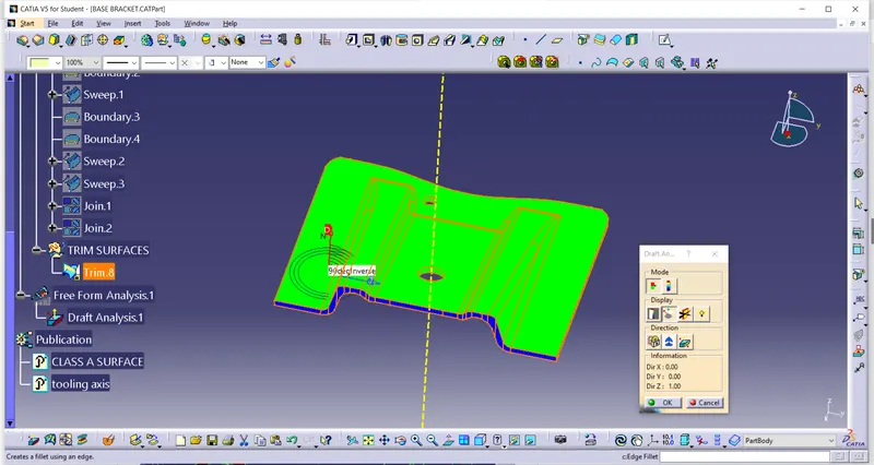
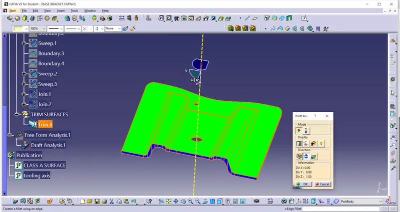
The draft analysis technique is used to analyze whether our part model created in CAD is manufacturable based on the draft condition applied.Minimum draft angle is considered as 3 degree.step 1) enter part in Catia.step 2)Go to Material Mode.step 3) go for draft analysis. step 4) drag axis bar to the tooling direction of part.step 5) check for draft and make parting line as per analysis.
Publication :-
Publication is use to easy access main command and inputs .