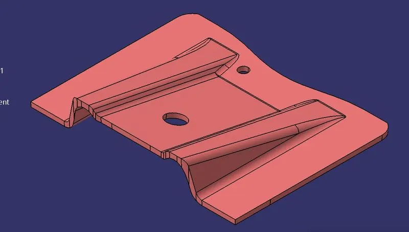
Week 9 - Challenge 1 - Base Bracket Design
Objective:
The objective of this challenge is to create the Base Bracket Plastic component through the given Class-A surface. By using the tooling axis to give the draft angle to create the thicken surface by using the class_B and class_C surface. Finally we'll do the draft analysis for this part.
Class_A_Surface:
Here we'll download the class_A _surface by using the above link.
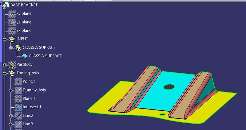
In this above A surface I decided to choose the center hole for creating the tooling axis. First I create the point on it's center then create a line on Z direction, then create a plane on it's point on YZ reference. After I decided to intersect this plane with surface, we'll get these output.
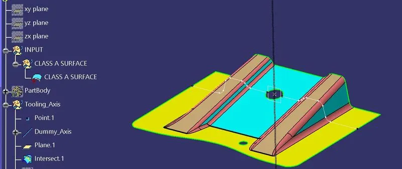
Then by using this intersecting lines I'll create the line on the two tapered directions by using there points on it and then I choose to create tooling axis by bisecting these 2 lines with the point 1. Then we'll get the tooling axis.Then we can change it's colour for the better view.
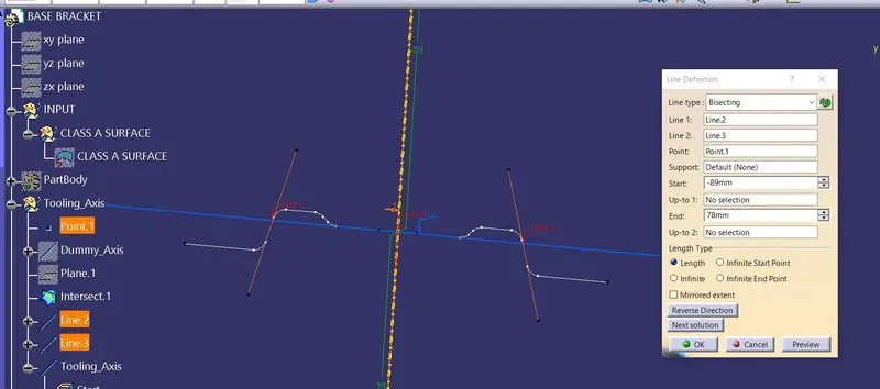
Class_B_Surface:
After creating the tooling axis we want to create the B_Surface offset to 2.5 mm. So we want to offset these surface.
Normal offset will not give the real time parameters on it. So first we have to offset the complicated shapes on the surface.
I decided to offset the two ribs on the surface.
The 3 surfaces of the rib is extracted, untrimmed and then extrapolated. After the expolation was done, it will be to trimmed and then offset to 2.5mm below.
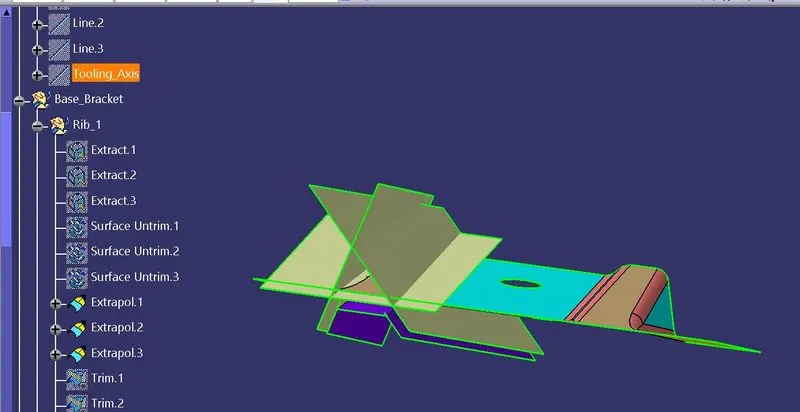
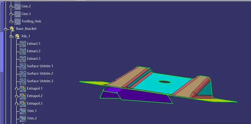
The same procedure is repeated for the rib 2.Then we'll get these surfaces.
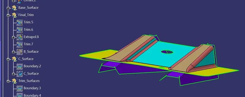
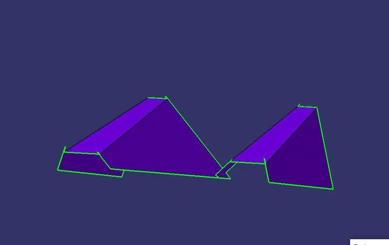
After offsetting these two ribs, we want to offset the base surface as well. Then we can extract, untrim and then extrapolate the base surface. We'll use the same procedure for both center and base surface in teh class_A_surface. Then finally we'll get these output.
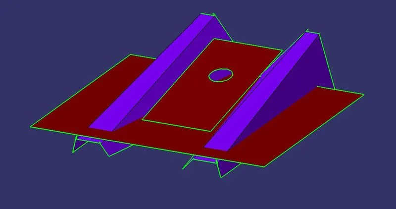
Then using the trim operation to get the final trim we'll get the B_Surface.
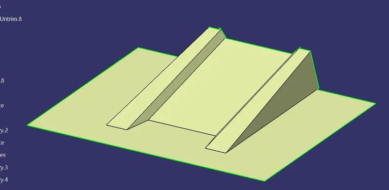
But we missed the fillet surface on the edges, I checked the A_surface as a reference it has normally 3mm radius on the edge fillets but in this offset surface we'll give the radius with the thickness dimension, So I added the tickess to the radius of this fillet to get the B_Surface. For this radius will be 3+2.5= 5.5 mm.
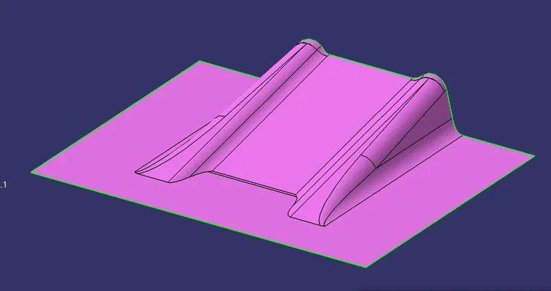
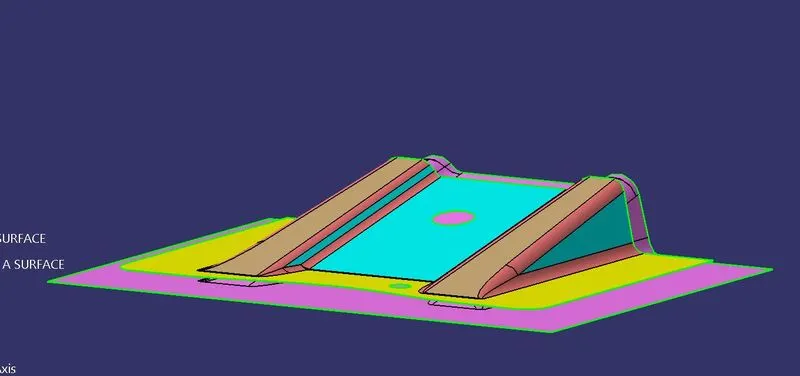
So, we are having the B_Surface.
After we want to give the thickess of the surface by using the class_C_Surface.
Class_C_Surface:
For creating the C_Surface I'm using the boundary of the A_Surface. Using the boundary of A_Surface we'll use the sweep tool to give the draft axis is tooling axis and give give the angle is 3deg. Finally we get the C_Surface.
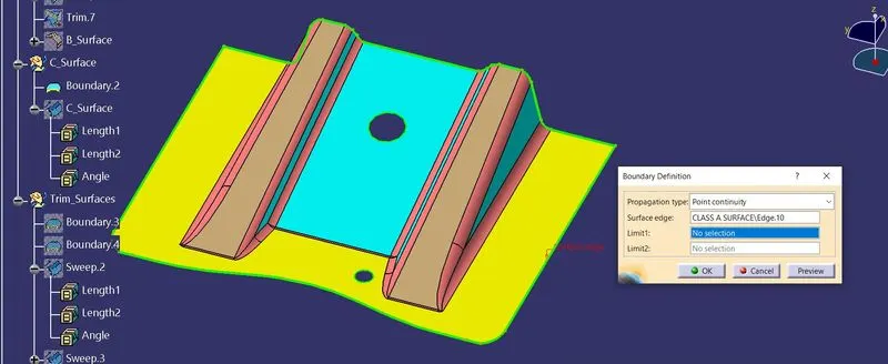
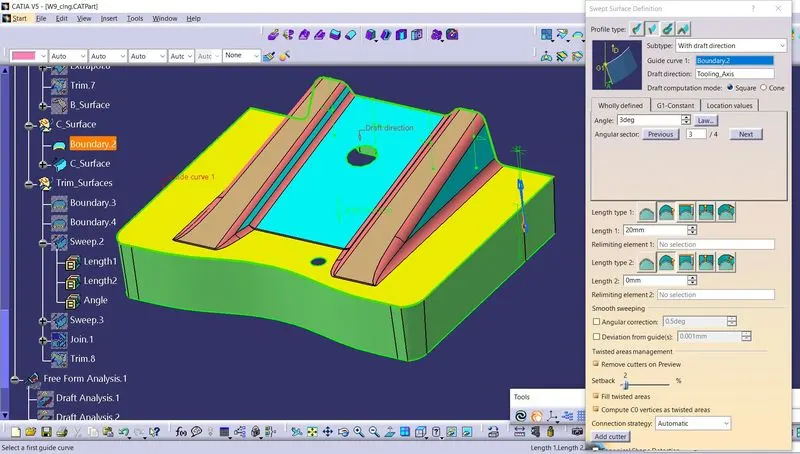
But it's not done for the C_surface, because we forgot the holes on the surface. We'll use the same for these two holes. Like the previous procedure use the boundary for these holes and then sweep it to 3deg on the C_surface direction.
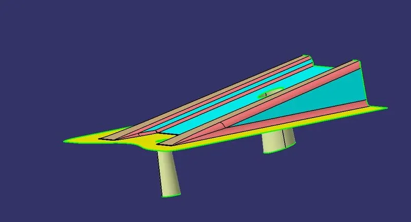
After we can use join tool to ge the final C_Surface on it.
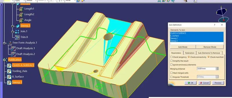
After getting the all 3 surfaces we can get the final output surface by using the trim option tool.
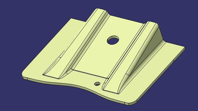
Draft Analysis:
After creatig all the surfaces we can do the draft analysis for that. In plastic design, the draft analysis or angle that is considered in the OEMs is 3 degree.
A_Surface:
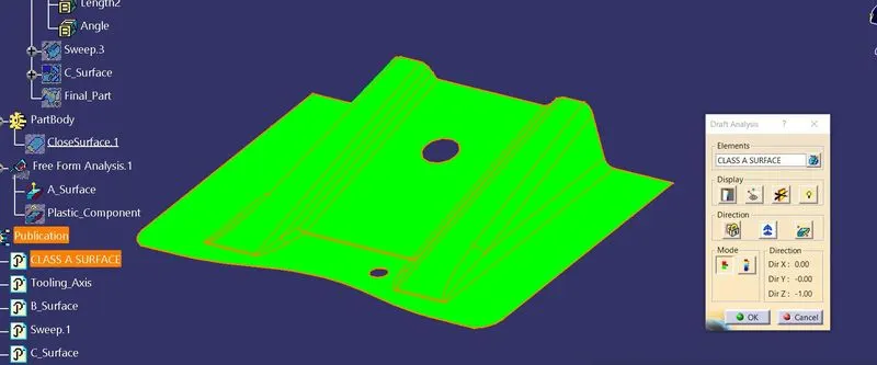
First we'll do the analysis for Class_A_surface. First we want to unhide class_A_Surface. Then go to Insert-> Analysis-> Feature Draft Analysis. Sometimes it'll some error for give material to this. We can make the part as material by using the material option. Then we'll do the draft analysis. For doing that we using the compass tool on the draft analysis window to place on the tooling axis and then lock it.
By clicking on the surface, the whole part turned into green color. If blue was visible that meant that the analysis was inversely done so just by flipping the direction, draft analysis.
The green region shows the part which is toolable or produceable by the molding machine and the draft angle is 3degree.
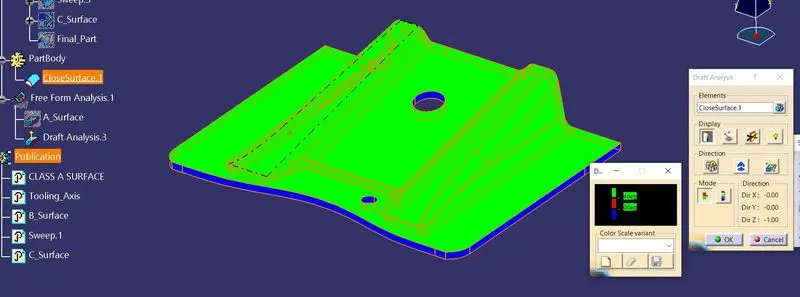
Blue color region states that the part can be allowed in some OEMs but still need to be improved for the other OEMs as the draft angle is more than 3 degrees.
Red color which is not there in this case states that the draft angle is less than 3 degree and cannot be produced or if produced would be faulty.
Plastic_Componenet:
Then we'll do the draft analysis for the final part also. We use the same procedure on the above, it will results like this.
Closed Surface:
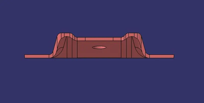
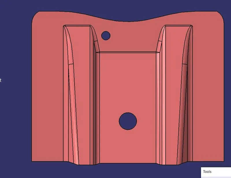
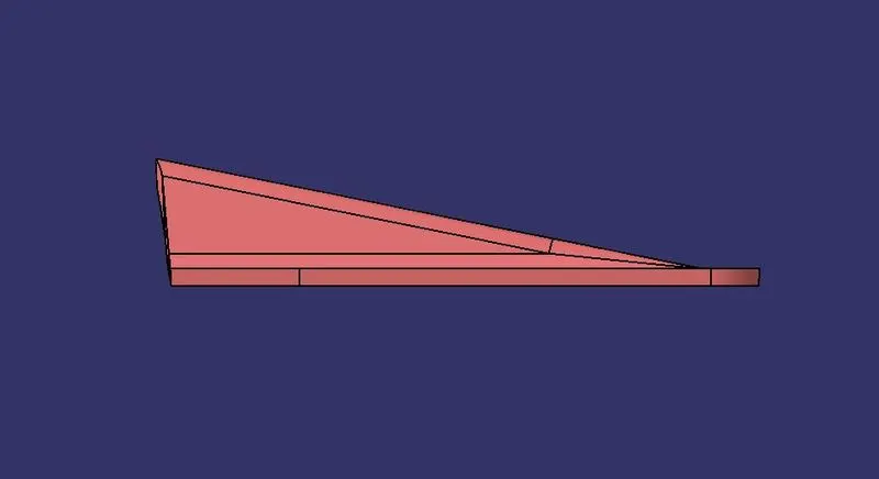
After creating final part we'll make it to solid by using the close surface tool in the part design workbench. Then finally we can get this output.
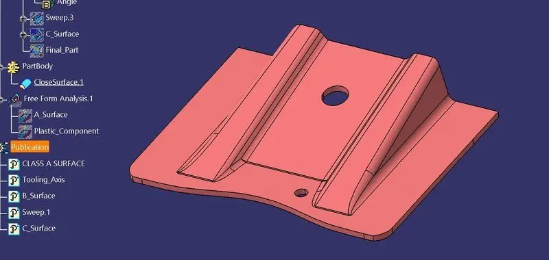
Solid model with Various Orientations:
Front View:
Top View:
Side View:
Isometric View: