Week 9 - Challenge 1 - Base Bracket Design
Base Bracket Design
AIM:
Create the Base Bracket Plastic component through the given Class-A surface. To begin with, the tooling axis for the given Class-A Surface should be created meeting the requirements of the draft angle and at the end perform the Draft analysis on the model.
Thickness of Plastic Part - 2.5 mm.
INTRODUCTION:
CLASS A:
Class 'A' surfaces are primarily used in the automotive environment and refer to those surfaces which are visible in a product. In other words: A - class surfaces are those aesthetic/free-form surfaces, which are visible to us (interior/exterior), and have an optimal aesthetic shape and high surface quality.
CLASS B:
Class B is a reference surface that is created by the design engineer and is a copy of the class A surface that is at a distance equal to the thickness of the part.
CLASS C:
Class C is again a reference surface that is created by the design engineer to connect Class A and Class B surface also known as the side wall of the surface
INPUT:
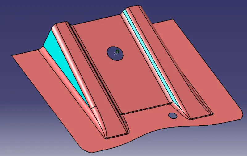
The below image shows the input class A surface given.
Step 1:
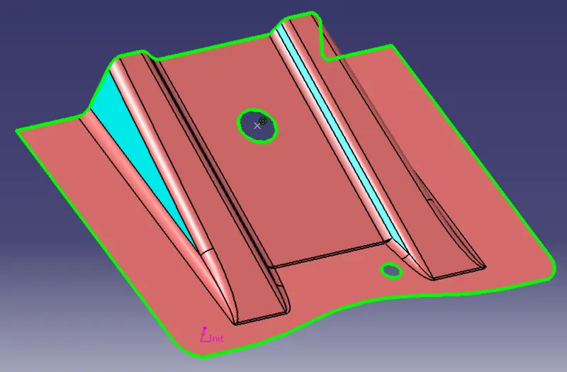
The given surface is checked with boundary or join command,whether it have closed boundaries and without patches.
Tooling Axis Creation:
Step 2:
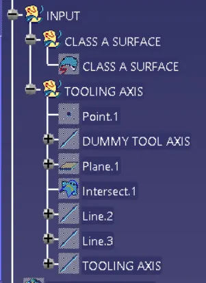
Create the dummy tooling axis by creating the centre point on the surface,create the intersect to check the cut section,where the angled surfaces in the surfaces to check it will create a problem or not while production using moulding.
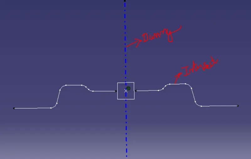
Create the line on the surfaces which causes the problem while production,create a bisect line from the two lines, to create the main tooling axis.
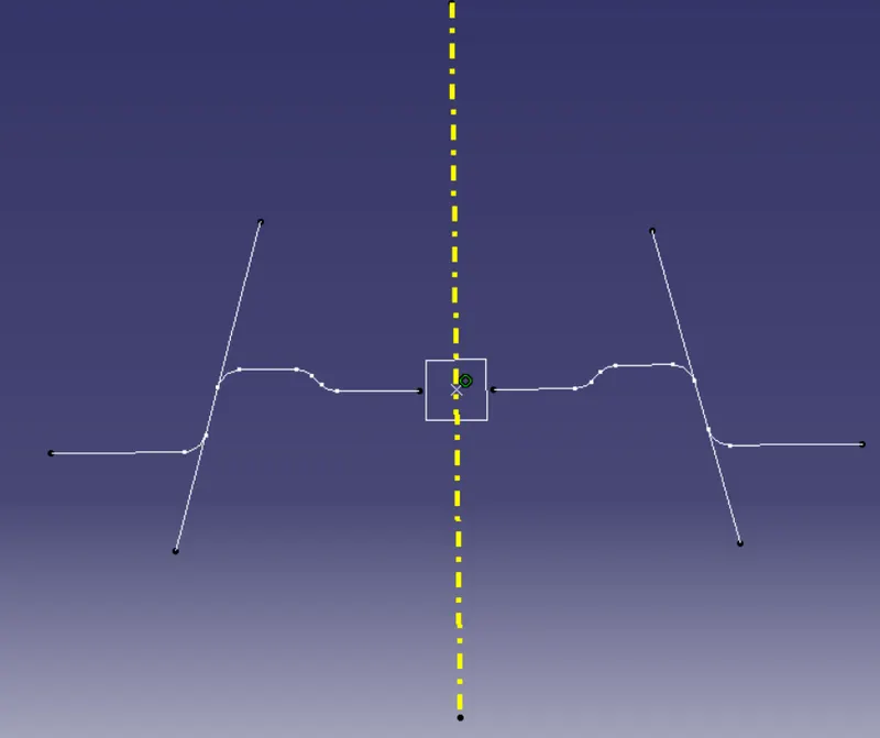
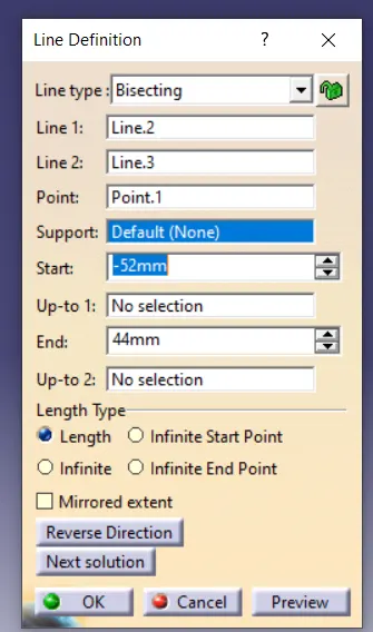
The final bisect line is the main tooling axis which is shown in yellow color dashed line.
Step 3:
Draft Analysis:
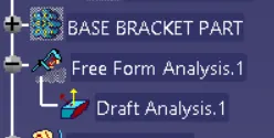
Draft analysis is done for the A surface.
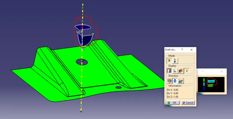
Open the Draft Analysis,give angle 2.9 or 3 deg.
click the compass center and drag it to the tooling axis.
click on the surface to check the draft degrees.
check the surfaces are shown in green and then it is good to do the B surface.
Step 4:
B-Surface Creation:
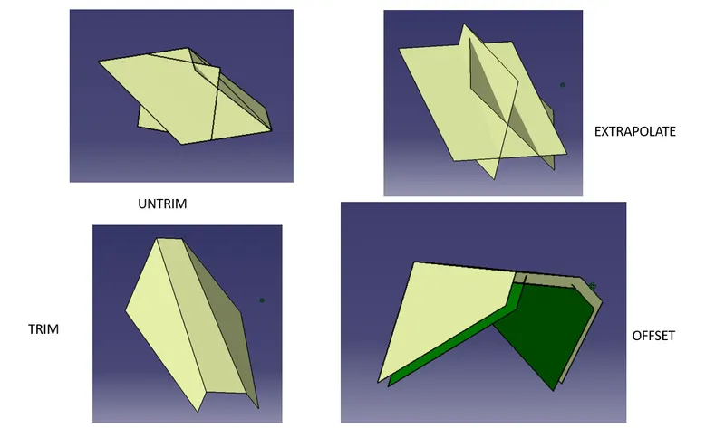
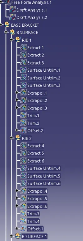
RIB 1:
Steps:
- Extract the rib surfaces from the A surface
- untrim the extracted surfaces
- Extrapolate the surfaces to trim
- trim the needed rib surface
- offset to the thickness of 2.5mm
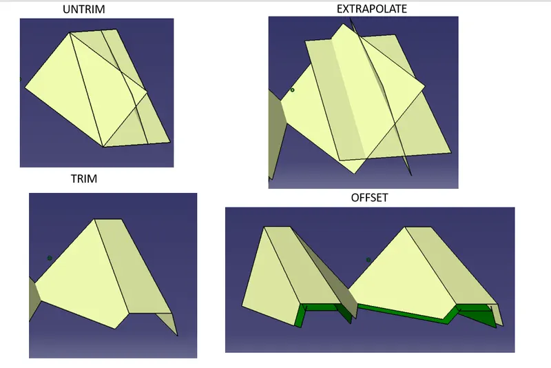
RIB 2:
- Extract the rib surfaces from the A surface
- untrim the extracted surfaces
- Extrapolate the surfaces to trim
- trim the needed rib surface
- offset to the thickness of 2.5mm
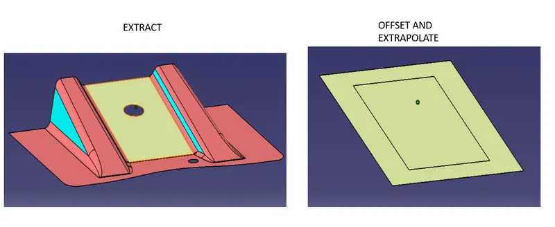
Extract the front surface and offset to the required thickness.
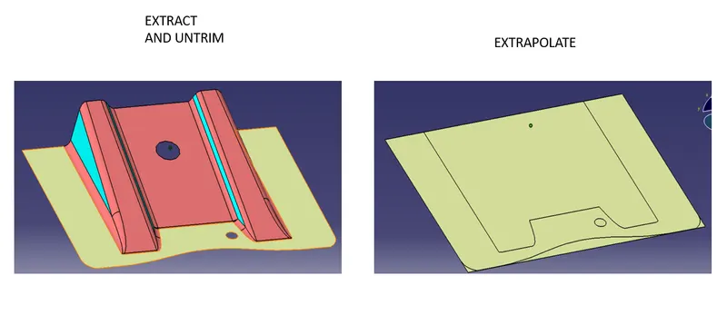
extrapolate the untrim surface to trimming.
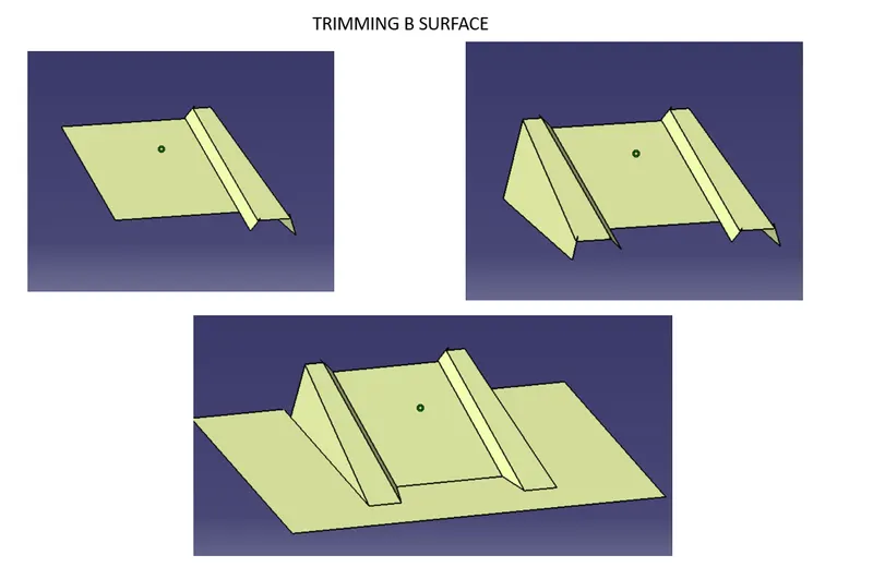
Trimming of B Surface:
The rib 1,rib 2,front and base surfaces trimmed to get the desired B Surfaces.
Edge Fillet command is used to create the fillets in B surface.
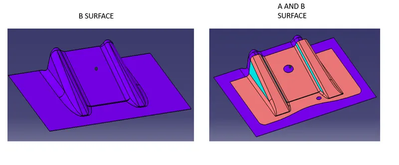
STEP 5:
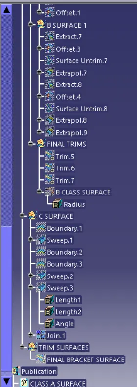
C SURFACES:
C Surfaces is created by below steps:
- Create the Boundary using boundary command
- Select Sweep command > With draft Direction > Select Tooling axis
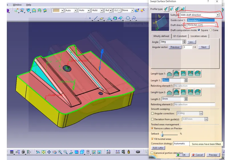
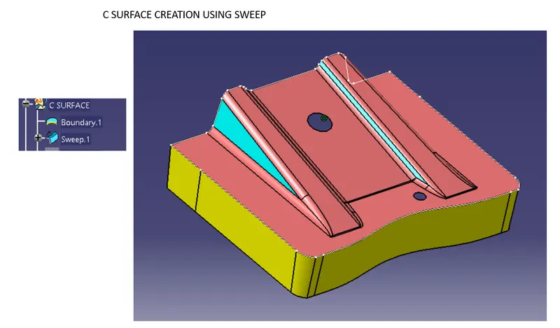
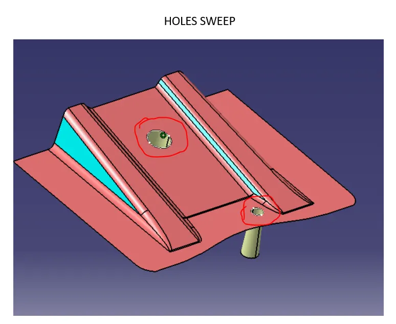
Create the sweep extrude of holes to create the C surface using the same sweep command.
STEP 6:
FINAL TRIMS:
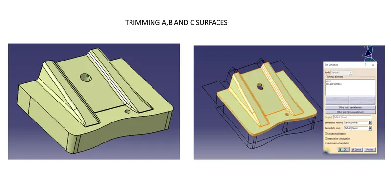
The final surface is get by trimming the joined A and C surfaces with the B surface as shown in the below figure.
STEP 7:
CLOSE SURFACE CREATION:
After creating the joined surfaces,
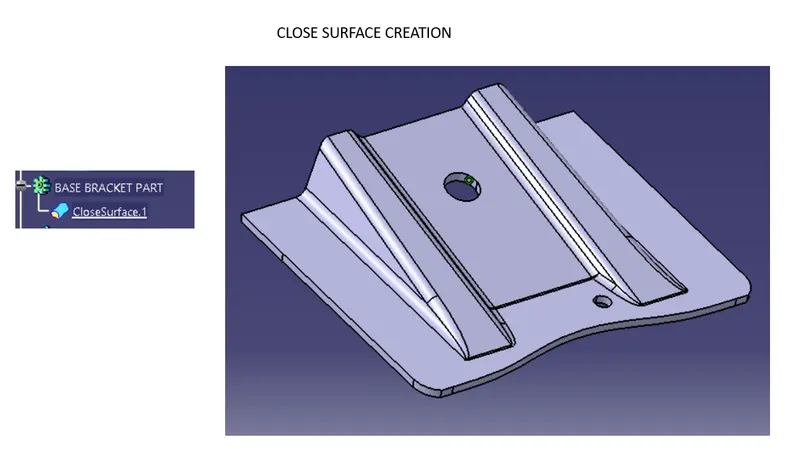
Go to part Design > ClosedSurfaces >Select the final trim
STEP 8:
FINAL DRAFT ANALYSIS:
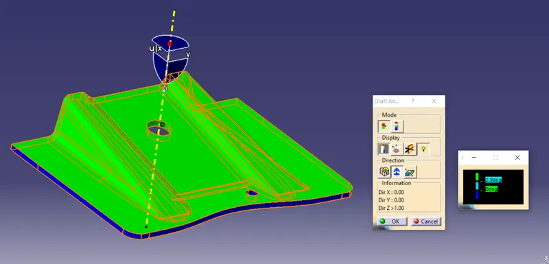
Finally draft analysis is done for the closed surface part,drag athe compass to the tooling axis and touch the surface of the part to get the draft analysis result.
It shows the green colour all over the surfaces,It says that the part designed is able to manufacture.
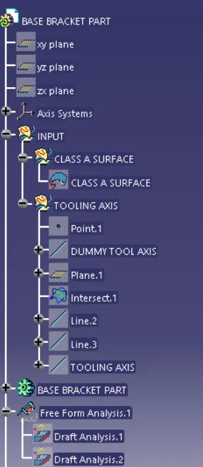
TREE STRUCTURE:
PUBLISH THE TOOLING AXIS AND A SURFACE FOR EASE WORKING.
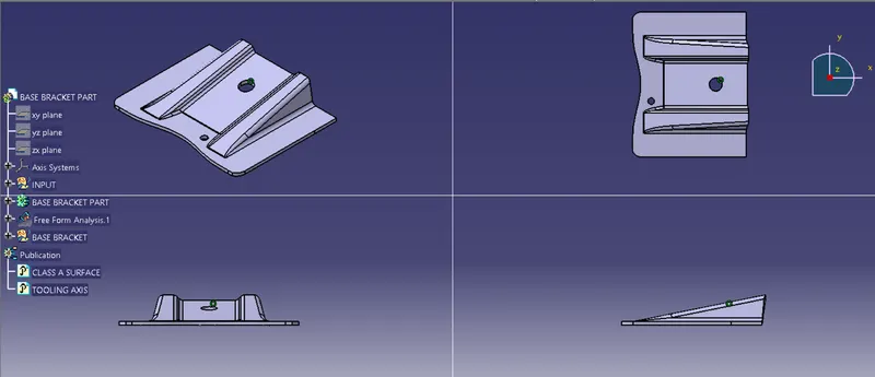
FINAL VIEW OF PART(CLOSED SURFACE)
CONCLUSION:
Using the given A surface of the Base bracket plastic component,the B and C surface is created with the correct tooling axis that meet the requirements of the draft angle and the draft analysis was performed to the model.